1
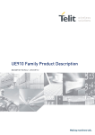
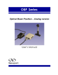
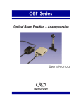
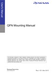
UM10408_1
DAC1x08 demonstrator: Demonstration board for DAC1x08D
Rev. 01.5 — 29 july 2010
User manual
Document information
Info
Content
Keywords
JESD204A, PCB2064-3, PCB2064-4.0, Demonstration board, DAC,
Labview, DAC1408D, DAC1208D, DAC1008D
Abstract
This document describes the use of DAC1x08D Demonstrator for the
JESD204A-compliant digital-to-analog DAC1x08D converters family.
UM10408_1
NXP Semiconductors
Demonstration Board for DAC1x08D
Revision history
Rev
Date
Description
1.5
2010-07-29
This document applies also to DAC1008D and DAC1208D demo board.
1.4
2010-05-05
Discrepancies fix and troubleshooting topic added.
1.3
2010-03-10
Update to V2.2 labview software
1.2
2010-02-01
Update jumper settings
1.1
2010-01-18
Marcom campaign II release. 64K FPGA option added.
1.0
2009-11-25
New demoboard for HVQFN64 package. Reference is PCB2064-3.0
0.3
2009-07-03
Update on clocks and on PCB2064-2.0
0.2
2009-06-11
Update
0.1
2009-01-29
Initial version.
Contact information
For additional information, please visit: http://www.nxp.com
For sales office addresses, please send an email to: [email protected]
UM10408_1
User manual
© NXP B.V. 2009. All rights reserved.
Rev. 01.5 — 29 july 2010
2 of 32
UM10408_1
NXP Semiconductors
Demonstration Board for DAC1x08D
1. Introduction
1.1 Setup overview
Fig 1 presents the connections to measure DAC1x08D Demonstrator.
DC Power supply for
complete board (6V/3A)
To spectrum
analyzer
To spectrum
analyzer
(1) PCB2064-3.0 overview
Fig 1. Demonstration board DAC1X08D setup
USB port for connection
to PC (USB and SPI
controller)
UM10408_1
User manual
© NXP B.V. 2009. All rights reserved.
Rev. 01.5 — 29 july 2010
3 of 32
UM10408_1
NXP Semiconductors
Demonstration Board for DAC1x08D
1.2 Essential Features of the Demonstration Board
(1) NXP serial DAC device (9x9mm package)
Fig 2. DAC1X08D with 4 lanes in pairs of CML compliant differential
Fig 2 shows the DAC1x08D in its environment. The input is a series CML connection
capable of sustaining a throughput rate of 3.125Gsps as specified by the JESD204A
standard.
The output is connected to a transformer and then to an SMA output. Alternatively, an
analog quadrature modulator can be used by means of de-soldering/soldering 0 ohms
resistors.
The logic device Field Programmable Gate Array (FPGA) is connected to the DAC1x08D
via 4 Lanes with each lane in differential CML referenced to the positive supply.
Moreover a synchronization signal, SYNC, is routed in differential also, between the
FPGA and the DAC1x08D.
UM10408_1
User manual
© NXP B.V. 2009. All rights reserved.
Rev. 01.5 — 29 july 2010
4 of 32
UM10408_1
NXP Semiconductors
Demonstration Board for DAC1x08D
SYNC
4 LANES
(1) Jesd204A serial interface
Fig 3. FPGA Logic device connected to the DAC1X08D via 4 Lanes and the SYNC
The board contains also a flash memory as shown in Fig. 4, to store the configuration file
of the FPGA. This flash memory is loaded automatically into the logic device at start up.
After the bit-stream has downloaded into the FPGA, the diode D1 lights up indicating that
everything has went well.
UM10408_1
User manual
© NXP B.V. 2009. All rights reserved.
Rev. 01.5 — 29 july 2010
5 of 32
UM10408_1
NXP Semiconductors
Demonstration Board for DAC1x08D
(1)
Fig 4. On board memory with LED D1 indicating FPGA up-loaded and running and D7 indicating USB host
detected
Furthermore, after connecting the USB port and installing the driver, the LED D7
indicates that the USB host has been detected and is up and running.
UM10408_1
User manual
© NXP B.V. 2009. All rights reserved.
Rev. 01.5 — 29 july 2010
6 of 32
UM10408_1
NXP Semiconductors
Demonstration Board for DAC1x08D
(1)
Fig 5. BP1 (Manual Reset) and BP2 (Manual upload of the flash content into the FPGA)
Push Button BP1 is a manual reset of the FPGA and the two DACs. User must press this
button each time he starts a new test.
Push Button BP2 is a manual upload of the FPGA contents from the flash memory. This
is automatically performed at power up of the board.
Dip switch SW1 is used to select the code loaded into the FPGA. The flash memory is
large enough to hold two codes. Default position is ON-ON.
Table 1.
SW1
Table description (optional)
0
1
Max size of the pattern
loaded into FPGA
memory
Max FPGA operating
frequency
ON
ON
8K samples
310Mhz
OFF
ON
30K samples
190Mhz
UM10408_1
User manual
© NXP B.V. 2009. All rights reserved.
Rev. 01.5 — 29 july 2010
7 of 32
UM10408_1
NXP Semiconductors
Demonstration Board for DAC1x08D
0
1
Max size of the pattern
loaded into FPGA
memory
ON
OFF
Do not use this setting
OFF
OFF
Do not use this setting
Max FPGA operating
frequency
Each time SW1 setting is modified, the FPGA code must be updated. Just press BP2 to
trigger the upload process and wait until D1 lit.
(1) Selecting the 30K mode
Fig 6. Configuring the FPGA
Larger memories allow DAC ACPR measurements.
The FPGA operating frequency equals the maximum DAC input data rate.
UM10408_1
User manual
© NXP B.V. 2009. All rights reserved.
Rev. 01.5 — 29 july 2010
8 of 32
UM10408_1
NXP Semiconductors
Demonstration Board for DAC1x08D
(1)
Fig 7. D9 – D16 indicates the status of the FPGA
There are two rows of LEDs. Each reflects the status of one of the Jesd204A transmitter:
D17~D24 are tied to the upper link and D8~D15 are tied to the lower one.
Table 2.
FPGA status LEDs
Table description (optional)
Upper
Lower
Meaning
D17
D8
always off
D18
D9
SYNC_REQUEST
UM10408_1
User manual
© NXP B.V. 2009. All rights reserved.
Rev. 01.5 — 29 july 2010
9 of 32
UM10408_1
NXP Semiconductors
Demonstration Board for DAC1x08D
Upper
Lower
Meaning
D19
D10
FPGA GTP0 lock status
D20
D11
FPGA GTP1 lock status
D21
D12
GTP0 reset done
D22
D13
GTP1 reset done
D23
D14
always off
D24
D15
FPGA Reset
At startup time or after pressing reset button, LEDs D9, D10, D11, D13, D18, D20,
D21,D22 should lit.
The SYNC_REQUEST signal is a synchronization request signal used at the beginning
of the transmission. It is always present between the FPGA and the DAC until the data is
transferred from the logic device to the DAC1x08D. It is also used by the receiver to
trigger loss of synchronization and requests re-initialization. When the data has been
transferred D9 (D18) turns off.
Using both DAC devices (IC13 & IC23) is optional. It is possible to hold IC23 (top
DAC1x08) in reset and then use only IC13 (bottom DAC). Pressing push button BP4
disables IC23. To reflect this state, Led D17~D24 are turned off.
Pressing the main reset button (BP1) will re-activate DAC IC23 as part of the FPGA reset
process.
UM10408_1
User manual
© NXP B.V. 2009. All rights reserved.
Rev. 01.5 — 29 july 2010
10 of 32
UM10408_1
NXP Semiconductors
Demonstration Board for DAC1x08D
(1)
Fig 8. Disabling DAC IC23
The clock signal can be generated on the board as there is a Phase Locked Loop (PLL)
available.
UM10408_1
User manual
© NXP B.V. 2009. All rights reserved.
Rev. 01.5 — 29 july 2010
11 of 32
UM10408_1
NXP Semiconductors
Demonstration Board for DAC1x08D
(1) Default configuration
Fig 9. On board clock generation
By default, the frame clock needed by the FPGA and the two DACs is provided by IC10.
In that mode, device internal VCO is used and locked to a 125Mhz reference oscillator.
The actual clock frequency provided to the DAC and FPGA is set via software.
Dip switch SW2 sets IC10 startup behavior.
Table 3.
SW2
IC10 startup behavior
Postion
ON
OFF
1
Load default registers settings at
startup. Resulting frequency will
No default registers settings at
UM10408_1
User manual
© NXP B.V. 2009. All rights reserved.
Rev. 01.5 — 29 july 2010
12 of 32
UM10408_1
NXP Semiconductors
Demonstration Board for DAC1x08D
Postion
2
ON
OFF
be 312.5Mhz.
startup.
Power down device
Device active.
Remark: the clock can also come externally through SMA connector J4. Multiplexers are
available so as to route the right clock signal to the devices, the DAC1x08D and the
FPGA. The clock source is selected using dipswitch SW3:
Table 4.
SW3
Clock source selection
Position
1
2
Action
ON
ON
On board PLL (IC10)
OFF
OFF
External clock (J4)
Other combinations will lead to
unexpected behavior
J4 is 50 ohms terminated. The recommended power is +13dBm.
UM10408_1
User manual
© NXP B.V. 2009. All rights reserved.
Rev. 01.5 — 29 july 2010
13 of 32
UM10408_1
NXP Semiconductors
Demonstration Board for DAC1x08D
(1) SW3 configured to select an external clock input
Fig 10. Using an external clock
UM10408_1
User manual
© NXP B.V. 2009. All rights reserved.
Rev. 01.5 — 29 july 2010
14 of 32
UM10408_1
NXP Semiconductors
Demonstration Board for DAC1x08D
2. Example
2.1 Setup example
USB SPI
DAC1408.exe
Input Data file1
(1)
Fig 11. DAC1X08D Demonstrator Hardware setup
UM10408_1
User manual
© NXP B.V. 2009. All rights reserved.
Rev. 01.5 — 29 july 2010
15 of 32
UM10408_1
NXP Semiconductors
Demonstration Board for DAC1x08D
3. SPI quick start
3.1 Install
The demonstration board is delivered with the following software:
Labview Runtime: LVRTE86f1std
Labview executable: DAC1408.exe
Appropriate drivers
These are stored as follows:
• Step 1
Connect the device to a USB port on your PC. Windows ‘Found New Hardware Wizard’
will be launched. Select ‘No, not this time’ from the options available and then click
‘Next’ to proceed with the installation.
UM10408_1
User manual
© NXP B.V. 2009. All rights reserved.
Rev. 01.5 — 29 july 2010
16 of 32
UM10408_1
NXP Semiconductors
Demonstration Board for DAC1x08D
• Step 2
Select ‘Install from a list or specific location (Advanced)’ as shown below and then
click ‘Next’.
• Step 3
UM10408_1
User manual
© NXP B.V. 2009. All rights reserved.
Rev. 01.5 — 29 july 2010
17 of 32
UM10408_1
NXP Semiconductors
Demonstration Board for DAC1x08D
Select ‘Search for the best driver in these locations’ and enter the file path of the
folder ‘DAC1408\CDM 2.04.16 WHQL Certified’ in the combo-box (‘C:\driver_2xx’ in the
example below) or browse to it by clicking the browse button. Once the file path has been
entered in the box, click ‘next’ to proceed.
• Step 4
Windows should then display a message indicating that the installation was successful.
Click ‘Finish’ to complete the installation for the first port of the device.
UM10408_1
User manual
© NXP B.V. 2009. All rights reserved.
Rev. 01.5 — 29 july 2010
18 of 32
UM10408_1
NXP Semiconductors
Demonstration Board for DAC1x08D
3.2 SPI interface
• Step 1
Install the LabVIEW Run-time Engine, LVRTE86f1std (if not already installed).
• Step 2
Start the LabVIEW application “DAC1408.exe”.
Run continuously
This is the main page of the GUI.
Click on the ‘run continuously’ button. The “SPI controller detected” marker should be
green to indicate correct communication between the software and the board.
• Step 3
Press the ‘clock settings’ button.
At startup, the on-board synthesizer is configured to generate 312.5Mhz for both DACs
and FPGA.
UM10408_1
User manual
© NXP B.V. 2009. All rights reserved.
Rev. 01.5 — 29 july 2010
19 of 32
UM10408_1
NXP Semiconductors
Demonstration Board for DAC1x08D
Press when
finished
FDAC indicator reflects the DAC frequency resulting from the current divider settings. It is
not the actual board frequency.
FFPGA indicator reflects the FPGA frequency resulting from the current divider settings.
It is not the actual board frequency.
To apply these settings to the board, the user must press the ‘Update registers’.
After each registers update, led D2 should lit. This reflects the correct frequency lock of
IC10.
When the DACs are set to use their internal pll then FDAC must equal FFPGA.
If the DACs are set in pll by-pass mode then the ratio FDAC over FFPGA must reflect the
interpolation ratio. The various synthesizer dividers are here for that purpose.
In the example below, FDAC = 4 x FFPGA. This means that the DAC is in pll bypass
mode and that the output sample rate equals four times the input samples rate.
UM10408_1
User manual
© NXP B.V. 2009. All rights reserved.
Rev. 01.5 — 29 july 2010
20 of 32
UM10408_1
NXP Semiconductors
Demonstration Board for DAC1x08D
Interpolation ratio
IC10 has an embedded flash memory. During power-on, it fetches the startup value from
there. The content of the flash can be over-written with the current settings using the
“Make reset value” button. At next power-up, these will be the default settings of the
frequency synthesizer.
UM10408_1
User manual
© NXP B.V. 2009. All rights reserved.
Rev. 01.5 — 29 july 2010
21 of 32
UM10408_1
NXP Semiconductors
Demonstration Board for DAC1x08D
Once finished, close the window using the red button ‘Exit’.
• Step 4
Press the ‘FPGA control’ button.
I data set
Q data set
This GUI is used to load the data that will be sent to the DAC by the FPGA.
Load a dataset/pattern provided in the folder DAC1408\Wave\, in the Path A.
Remark: the format of the patterns provided is a simple text file, with 4 hexadecimal
numbers per row and a maximum of 8192 or 30720 rows.
Remark: if the FPGA code selected with switch SW1 is a 30K samples, then 30K button
must be on.
Remark: Clicking the “write” button automatically triggers the TX FPGA registers
configuration.
Remark: Write order is important. Always write Path A data set before Path B one.
For simple signals (sine wave), one can turn the ‘Duplicate & auto-start’ feature on.
UM10408_1
User manual
© NXP B.V. 2009. All rights reserved.
Rev. 01.5 — 29 july 2010
22 of 32
UM10408_1
NXP Semiconductors
Demonstration Board for DAC1x08D
Then there is no need to load Path B, as the content of Path A is automatically copied
into Path B
If FPGA is in 30K
mode, turn this
Only I data set is
option on
needed
Duplicate path A
pattern to path B
Once finished, close the window using the red button ‘Exit’.
• Step 5
Press ‘DAC_1 control’ button.
There are three ways to configure the DAC:
UM10408_1
User manual
© NXP B.V. 2009. All rights reserved.
Rev. 01.5 — 29 july 2010
23 of 32
UM10408_1
NXP Semiconductors
Demonstration Board for DAC1x08D
1. Using the first three tabs: “COMMon – PHINCO”, “DAC_CFG” and “DAC_AUX”, the
user can configure the device in a graphical way,
2. Using the tabs: “Page0”, “Page1”, “Page2”, “Page3”, “Page4”, “Page5”, “Page6” and
« Page7 », the user can access the device registers in detail. This requires an
advanced knowledge of the device.
3. Using tab “Execute_DAC_cmd_file”, the user can run presets that configure the DAC
in a known behaviour.
The first method is depicted below:
Use the buttons, sliders and numeric fields to set the DAC configuration. Then, once you
are finished, press “DAC Registers-update” and “Jesd204 link-update” buttons. The
expected signal should be available.
The “Jesd204 link-update” button needs to be pressed only once between two resets.
Once the jesd204a link is running, the user can change the DAC settings (e.g.
minus_3dB) without restarting the link. He just needs to press “DAC Registers-update”
to see the changes.
UM10408_1
User manual
© NXP B.V. 2009. All rights reserved.
Rev. 01.5 — 29 july 2010
24 of 32
UM10408_1
NXP Semiconductors
Demonstration Board for DAC1x08D
The third method is accessible via the tab “Execute_DAC_cmd_file”.
This GUI is used to load script file that contains registers setting for the DAC. These are
ASCII files that can be modified at will.
Load a command file provided with the software at the following folder:
DAC1408\Settings
Then press the button ‘Write’ to configure the device.
Led D9 should now turn off to indicate that the Jesd204A SYNC request signal is deasserted. This means that the DAC and the FPGA are now well synchronized.
The naming convention for the scripts files is the following:
•
2x: 2 times interpolation filter turned on,
•
4x: 4 times interpolation filter turned on,
UM10408_1
User manual
© NXP B.V. 2009. All rights reserved.
Rev. 01.5 — 29 july 2010
25 of 32
UM10408_1
NXP Semiconductors
Demonstration Board for DAC1x08D
•
8x: 8 times interpolation filter turned on,
•
pll-on: DAC’s internal pll is used to generate output sample rate,
•
pll-bypass: output sample rate has to be provided from the main synthesizer,
•
ssbm: DAC’s internal NCO plus single side band modulator is turned on,
Once finished, close the window using the red button ‘Exit’.
• Step 6
Press ‘DAC_2 control’ button.
Proceed like Step 5 to configure the second DAC labeled IC23.
Signals will only be available at DACs outputs when both devices are configured. This is
because the SYNC_REQUEST signal of each DAC is combined inside the TX FPGA, as
stated in the jesd204a specification.
Led D18 should now turn off to indicate that the Jesd204A SYNC request signal is deasserted. This means that the DAC and the FPGA are now well synchronized.
Once finished, close the window using the red button ‘Exit’.
UM10408_1
User manual
© NXP B.V. 2009. All rights reserved.
Rev. 01.5 — 29 july 2010
26 of 32
UM10408_1
NXP Semiconductors
Demonstration Board for DAC1x08D
4. Annex 1: default dip-switches and jumpers settings
Table 5.
SW1 default
FPGA flash
1
2
ON
ON
Table 6.
SW2 default
IC10 registers settings
1
2
ON
OFF
Table 7.
SW3 default
Main clock input
1
2
ON
ON
Table 8.
SW4 default
FPGA configuration
1
2
3
4
5
6
7
8
OFF
ON
OFF
ON
ON
ON
ON
ON
Table 9.
SW5 default
IC19 configuration
1
2
OFF
OFF
Table 10. ST2 default
SPI 3W/4W mode
1
OFF
UM10408_1
User manual
© NXP B.V. 2009. All rights reserved.
Rev. 01.5 — 29 july 2010
27 of 32
UM10408_1
NXP Semiconductors
Demonstration Board for DAC1x08D
Table 11. ST1 default
Optional VCXO power supply
1
ON
UM10408_1
User manual
© NXP B.V. 2009. All rights reserved.
Rev. 01.5 — 29 july 2010
28 of 32
UM10408_1
NXP Semiconductors
Demonstration Board for DAC1x08D
5. Annex 2: Troubleshooting
5.1 Multiples FT2232 devices connected to the host PC
DAC1x08D demo board features a FT2232D USB to SPI bridge IC.
When multiple boards featuring the same IC are connected to the host PC, the software
is not able to differentiate them. Commands shall be sent to the wrong system.
To prevent this, one should make sure that there is only one FT2232D device connected
to the host at a time.
5.2 Sanity checks if the system doesn’t generate the expected waveform
1. Is the FLASH led (D1) on?
If not, check SW1 switch setting,
2. Is the USB led (D7) on?
If not, then unplug and plug the USB cable from the host PC,
3. Is main synthesizer led (D2) on?
If not, then one needs to retune the pll dividers settings (refer to SPI interface). Make
sure that the ‘VCO out of range’ indicator isn’t on.
4. Are the FPGA leds (D9, D10, D11, D12, D13, D18, D19, D20, D21, D22) on?
If not, press main reset push button (BP1).
If this doesn’t solve the issue, check switches SW3 according to the clock source
used.
5. Are the jesd204a links synchronized?
After configuring the FPGA and both DACs (refer to SPI interface), led D9 and D18
should be off to signify that all links are synchronized.
If one of them is still on, this is probably due to improper clock configuration.
6. Every led is on or off as expected, but the output spectrum does not look good.
Check how the pattern memory size has been configured on the board (switch SW1)
and in the software (tab ‘FPGA control’). Both settings should be aligned, i.e. 8K or
30K.
UM10408_1
User manual
© NXP B.V. 2009. All rights reserved.
Rev. 01.5 — 29 july 2010
29 of 32
UM10408_1
NXP Semiconductors
Demonstration Board for DAC1x08D
6. Legal information
6.1 Definitions
Draft — The document is a draft version only. The content is still under
internal review and subject to formal approval, which may result in
modifications or additions. NXP Semiconductors does not give any
representations or warranties as to the accuracy or completeness of
information included herein and shall have no liability for the consequences
of use of such information.
Applications — Applications that are described herein for any of these
products are for illustrative purposes only. NXP Semiconductors makes no
representation or warranty that such applications will be suitable for the
specified use without further testing or modification.
Export control — This document as well as the item(s) described herein
may be subject to export control regulations. Export might require a prior
authorization from national authorities.
6.3 Licenses
6.2 Disclaimers
General — Information in this document is believed to be accurate and
reliable. However, NXP Semiconductors does not give any representations
or warranties, expressed or implied, as to the accuracy or completeness of
such information and shall have no liability for the consequences of use of
such information.
Purchase of NXP <xxx> components
<License statement text>
6.4 Patents
Right to make changes — NXP Semiconductors reserves the right to make
changes to information published in this document, including without
limitation specifications and product descriptions, at any time and without
notice. This document supersedes and replaces all information supplied prior
to the publication hereof.
Notice is herewith given that the subject device uses one or more of the
following patents and that each of these patents may have corresponding
patents in other jurisdictions.
Suitability for use — NXP Semiconductors products are not designed,
authorized or warranted to be suitable for use in medical, military, aircraft,
space or life support equipment, nor in applications where failure or
malfunction of a NXP Semiconductors product can reasonably be expected
to result in personal injury, death or severe property or environmental
damage. NXP Semiconductors accepts no liability for inclusion and/or use of
NXP Semiconductors products in such equipment or applications and
therefore such inclusion and/or use is for the customer’s own risk.
Notice: All referenced brands, product names, service names and
trademarks are property of their respective owners.
<Patent ID> — owned by <Company name>
6.5 Trademarks
<Name> — is a trademark of NXP B.V.
UM10408_1
User manual
© NXP B.V. 2009. All rights reserved.
Rev. 01.5 — 29 july 2010
30 of 32
UM10408_1
NXP Semiconductors
Demonstration Board for DAC1x08D
7. Index
J
Jesd204A........................................................................... 4
S
Setup ................................................................................. 15
SPI ..................................................................................... 16
UM10408_1
User manual
© NXP B.V. 2009. All rights reserved.
Rev. 01.5 — 29 july 2010
31 of 32
UM10408_1
NXP Semiconductors
Demonstration Board for DAC1x08D
8. Contents
1.
1.1
1.2
2.
2.1
3.
3.1
3.2
4.
5.
Introduction .........................................................3
Setup overview...................................................3
Essential Features of the Demonstration Board.4
Example .............................................................15
Setup example .................................................15
SPI quick start ...................................................16
Install................................................................16
SPI interface.....................................................19
Annex 1: default dip-switches and jumpers
settings ..............................................................27
Annex 2: Troubleshooting ................................29
5.1
5.2
6.
6.1
6.2
6.3
6.4
6.5
7.
8.
Multiples FT2232 devices connected to the host
PC ....................................................................29
Sanity checks if the system doesn’t generate the
expected waveform ..........................................29
Legal information ..............................................30
Definitions.........................................................30
Disclaimers.......................................................30
Licenses ...........................................................30
Patents .............................................................30
Trademarks ......................................................30
Index ...................................................................31
Contents .............................................................32
continued >>
UM10408_1
User manual
© NXP B.V. 2009. All rights reserved.
Rev. 01.5 — 29 july 2010
32 of 32