1
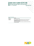
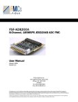
INTEROPERABILITY REPORT Interoperability report between Altera FPGA and IDT DAC Rev. 1.0 — 01/06/2014 Info Content Keywords JESD204B, DAC1658D/1653D, DAC1658Q/53Q , Altera®, ARRIA V®, Stratix V®, Cyclone V® Abstract This document describes the tests that have been performed between IDT® JESD204B DAC and Altera FPGA development kit supplied with MTI’s IPC-JESD204-B IP solution. IDT INTEROPERABILITY REPORT Revision history Rev Date Description Author 1.0 2014-01-06 Initial revision with Arria V GT dev kit P. Lieutaud, IDT HSC DAC Application Engineer. Contact information For additional information, please visit: http://www.idt.com © IDT. 2014. All rights reserved. Rev. 1.0 — 01/06/2014 2 of 13 IDT INTEROPERABILITY REPORT 1.1 Introduction: The goal of this document is to detail tests performed between silicon devices. As result one can claim that they are compatible from the perspective of the implementation of the JESD204B standard. 1.2 Scope: Interoperability testing shall be limited to existing DAC and FPGA dev kit hardware. 1.3 Hardware setup 1.3.1 IDT DAC165xD demo board The board used is referenced as DAC1658D1G5-DB or DAC1658D1G5-DB. Board schematic and layout are available from http://www.idt.com Its main characteristics are: One dual high-speed serial JESD204B DAC with four lanes input. Populated device can be DAC1658D1G5NLGA8 or DAC1653D1G5NLGA8 One (SAMTEC FMC) high density connector to interface with compatible carrier board One USB to SPI master device. It can be bypassed and the demo board can be controlled from the carrier through the FMC connector On-board voltage regulators for all devices on the board Clock divider (by 1, 2, 4, 8 or 16) to drive carrier board clock input The DAC1653D and the DAC1658D are high-speed high-performance 16-bit dual channel Digital-to-Analog Converters.(DACs). The devices provide sample rates up to 2 Gsps with selectable 2X, 4X and 8X interpolation filters optimized for multi-carrier and broadband wireless transmitters. The DAC165xD integrates a JEDEC JESD204B compatible high-speed serial input data interface running up to 10 Gbps allowing dual channel input sampling at up to 1 Gsps over four differential lanes. There are two versions of the DAC165xD: • Low common-mode output voltage (part identification DAC1653D1G5NLGA8) • High common-mode output voltage (part identification DAC1658D1G5NLGA8) An optional on-chip digital modulator converts the complex I/Q pattern from baseband to IF. The mixer frequency is set by writing to the Serial Peripheral Interface (SPI) control registers associated with the on-chip 40-bit Numerically Controlled Oscillator (NCO). This accurately places the IF carrier in the frequency domain. The 16-bit phase adjustment feature, the 12-bit digital gain and the 16-bit digital offset enable full control of the analog output signals. The DAC165xD is compatible with device subclass 0 and 1 of the JEDEC JESD204B standard, guaranteeing deterministic and repeatable interface latency using the differential SYSREF signal. The device also supports harmonic clocking to reduce system-level clock synthesis and distribution challenges. © IDT. 2014. All rights reserved. Rev. 1.0 — 01/06/2014 3 of 13 IDT INTEROPERABILITY REPORT Multiple Device Synchronization (MDS) enables multiple DAC channels to be sample synchronous and phase coherent to within one DAC clock period. MDS is ideal for LTE and LTE-A MIMO transceiver applications. The DAC165xD includes a 2, 4 or 8 divider to achieve the best possible noise performance at the analog outputs, allowing harmonic clocking through the system. 1.3.2 IDT DAC165xQ demo board The board used is referenced as DAC1658Q1G5-DB or DAC1653Q1G5-DB. Board schematic and layout are available from http://www.idt.com . Its main characteristics are: One quad output high-speed serial JESD204B DAC with 8 lanes input, One (SAMTEC FMC) high density connector to interface with compatible carrier board, One USB to SPI master device. It can be bypassed and the evaluation board can be controlled from the carrier through the FMC connector, On-board voltage regulators for all devices on the board, Clock divider (by 1, 2, 4, 8 or 16) to drive carrier board clock input. The DAC1653Q1G5NAGA and the DAC1658Q1G5NAGA are high-speed highperformance 16-bit Quad channel Digital-to-Analog Converters with similar feature sets as DAC1653D and the DAC1658D devices ( ref to 1.3.1 ). The DAC165xQ includes a very low noise bypass-able integrated Phase-Locked Loop (PLL).This PLL is fully integrated and does not need any external passive components. 1.3.3 Altera Arria V GT development kit The hardware used is referenced as Arria V GT FPGA Development Board. The main features are Two Arria V GT FPGA 5AGTD7K3F40I3N in the 1517-pin FineLine BGA (FBGA) package, FPGA configuration circuitry, Clocking circuitry, Two high-speed mezzanine card (HSMC) connectors, One FMC port, DDR3 SDRAM, For a full list of features please visit the Arria V GT Development Kit web page at http://www.altera.com/products/devkits/altera/kit-arria-v-gt.html © IDT. 2014. All rights reserved. Rev. 1.0 — 01/06/2014 4 of 13 IDT INTEROPERABILITY REPORT 1.3.4 MTI’s IPC-JESD204-B Applications and Benefits The applications for MTI’s IPC-JESD204-B IP are related to Data Converters or DSP (Digital Signal Processing) environments required for radar, medical imaging, wireless and cellular, military and aerospace just to mention a few. The IP implementation is made in RTL (VHDL-93) and it supports any FPGA, ASSP or ASIC technologies. The MTI’s IPC-JESD204-B offers the following competitive advantages: Support of rates up to 12.5 Gbps* with each Transmitter or Receiver core Support for FPGA, ASSP and ASIC silicon target either Data Converter or DSP 32-bits internal data processing with clock frequency 1/40 of baud rate in use enable usage in low end and mid end FPGAs MCDA-ML (Multiple-Converter Device Alignment, Multiple-Lanes) o Disabling of features mandatory to a class MCDA-ML module, if connected to a device pertaining to a class that does not support these features (JESD204 standard). Support run-time programmable configuration for key parameters o L, M, F, N, HD, SCR, CS o Support for deterministic latency (subclass 1) o Support for backward compatibility to JESD204A (subclass 0) o Insertion of tail bits are performed based on register settings. Both constant and low DC content tail bits are supported. o Support for built in test modes Support for error handling Includes 8b10b coding block Separate CPU interface for control and monitoring © IDT. 2014. All rights reserved. Rev. 1.0 — 01/06/2014 5 of 13 IDT INTEROPERABILITY REPORT Features The JESD204B Receiver and Transmitter modules are fully compliant to the JESD204B.01 2012 standard, with the following feature set as a subset of the entire specification: FEATURE LINE RATE DESCRIPTION LOW END FPGA / ASIC VALUE 3 GBPS* RECEIVER X TRANSMITTER X MID END FPGA / ASIC MID END FPGA / ASIC HIGH END FPGA / ASIC 6 GBPS* 10 GBPS* 12.5 GBPS* X X X X X X L M NUMBER OF LANES NUMBER OF CONVERTERS 1 – 8 RANGE 1 – 8 RANGE X X X X F N N’ HD NUMBER OF OCTETS SAMPLE RESOLUTION SAMPLE ENVELOPE HIGH DENSITY MODE X X X X X X X X SCR CF CS SCRAMBLING CONTROL BITS PER FRAME CONTROL BITS PER SAMPLE X X X X X X SUBCLASS 0 SUBCLASS 1 SUBCLASS 2 LINE CODING TEST MODES BACKWARD COMPATIBLE DETERMINISTIC LATENCY DETERMINISTIC LATENCY 8B10B BUILT-IN K.28.5 BUILT-IN ILA CODE GROUP SYNC. LANE SYNC. LANE CONFIG. 1, 2, 4, 8, AND 16 7 – 16 BITS RANGE 8, 12, 16, 20 1, 0 FOR N’=8, 16 1 FOR N’ = 12, 20 1, 0 0 0 – 3 BITS RANGE (PROGRAMMABLE) SYNC_B SYSREF SYSCLK X X X X X X X X X X X X X X X X Table 1: Features of the Receiver and Transmitter modules * Maximum rates on FPGA / ASIC depends on actual family, speed grade / technology process respectively Standard Deliverables Item Deliverables Description RTL Code (encrypted) Regression Test Bench Test Cases Timing Constraint File Documentation Datasheet User Manual Release Note Regression Test Report Simulation IOT Reports Hardware IOT Reports Logs Synthesis Report Test Log Receiver X X (O) Transmitter X X (O) X (O) X (O) X X X X X X X X X X X X X X X X X X Table 2: Standard Deliverables © IDT. 2014. All rights reserved. Rev. 1.0 — 01/06/2014 6 of 13 IDT INTEROPERABILITY REPORT The JESD204B IP FPGA is provided from MTI and is accessible from following web pages: http://www.mti-mobile.com/products/ipc-interfacing/ipc-jesd204-b/ Demo version can be requested here: http://www.mti-mobile.com/products/ipc-interfacing/ipc-jesd204b-altera/ © IDT. 2014. All rights reserved. Rev. 1.0 — 01/06/2014 7 of 13 IDT INTEROPERABILITY REPORT 1.4 1.5 Hardware setup The picture below gives an overview of the used configuration: (1) Fig 1. ArriaV GT dev kit with DAC1658D1G5-DB As FMC connector is connected only to FPGA2, the FPGA design is targeting that device. The frequency generator is connected to DAC board DAC_CK SMA connector. Reference clock to FPGA is supplied from the DAC board via FMC connector. To supply the correct frequency, S0, S1 and S2 jumpers have to be properly set to divide down by 4. For example, if the DAC clock frequency is 1.2GHz, the FPGA reference clock is 300MHz and the data rate on the lanes will be 6Gbps. DAC must be set to operate in by 2 interpolation and use all the 4 lanes. © IDT. 2014. All rights reserved. Rev. 1.0 — 01/06/2014 8 of 13 INTEROPERABILITY REPORT IDT Interoperability report 2. Test results 2.1 Setup 1 Setup 1 is built around an ArriaV GT dev. Kit using MTI’s IPC-JESD204-B IP and DAC1658D demonstration board. The following table details the tests carried out and the results. Table 1. Tests performed using setup 1 Unless otherwise specified, tests are conducted at bitrate of 6Gbps. Test number Test Description Interoperable Notes 1 Sync request DAC asserts SYNC low Yes SYNC state is reported using a LED on the FPGA carrier board. 2 K28.5 DAC detects K28.5 transmitted by TX Yes DAC reports that it has received K28.5. 3 Code group synchronization DAC has properly received more than 4 K28.5 Yes DAC synchronization state machine has entered CS_DATA state. DAC has also de-asserted SYNC signal. 4 Inter Lane Alignment Check that the DAC Yes has received at least 4 multi frames. Check ILA flag inside the DAC. 5 Inter Lane Alignment Subclass0 only: check that more than 4 multi frames is supported. No Not supported in TX IP. 6 Inter Lane Alignment Check that the DAC has achieved ILA. Yes DAC ila_rcv_flag is high. 7 Inter Lane Alignment Check that the DAC has achieved ILA when K=32 Yes DAC ila_rcv_flag is high. 8 Configuration data Check that the DAC has received the correct expected configuration data. Yes Check DAC received configuration data. © IDT. 2014. All rights reserved. Rev. 1.0 — 01/06/2014 9 of 13 INTEROPERABILITY REPORT IDT Interoperability report Test number Test Description Interoperable Notes 9 Data phase Test that the expected waveform is obtain at the DAC outputs. Yes Check with a spectrum analyzer for a clean sine wave at output. 10 Character replacement Check that the DAC still outputs correct data if character replacement is disabled at TX. Yes Check for a clean sine wave at output. No K28.3 or K28.7 detected by DAC. 11 Framing LMF = 421 Yes Check for a clean sine wave at output. 12 Framing LMF = 422 No S = 2 not supported by TX design. 13 Framing LMF = 222 Yes Check for a clean sine wave at output. 14 Framing LMF = 124 Yes Check for a clean sine wave at output. 15 Scrambling Enable scrambler and check data at the output. Yes Performed using a constant data and SBER testing mode inside the DAC. 16 3.125Gbps data rate Yes Check for a clean sine wave at DAC output. 17 6.375Gbps data rate Yes Check for a clean sine wave at DAC output. 18 10Gbps Yes Check for a clean sine wave at DAC output. Tested LMF=222 as Arria V GT kit features 2 TRX up to 10Gps on FMC connector. 19 Subclass 1 Check data contents at Yes the output of the DAC. Check for a clean sine wave at output. 20 Subclass 1 Check that latency is constant from start up to start up. Check that overall system latency uncertainty is with +/- 1 DAC clock period. 21 Subclass 2 Check data contents at No Yes DAC and TX IP do not © IDT. 2014. All rights reserved. Rev. 1.0 — 01/06/2014 10 of 13 INTEROPERABILITY REPORT IDT Interoperability report Test number Test Description Interoperable the output of the DAC. Notes support subclass 2. 22 Test: STLTP Test short transport layer test pattern Yes Scrambler and descrambler enabled at both side of the link. F=1 23 Test: LTLTP Test long transport layer test pattern No Not supported by DAC 24 Test: JTSPAT Check error free channel No Not supported by TX IP 2.2 Setup 2: Setup 2 is built around an Arria V GT dev Kit and DAC1658Q1G5-DB demonstration board. © IDT. 2014. All rights reserved. Rev. 1.0 — 01/06/2014 11 of 13 INTEROPERABILITY REPORT IDT Interoperability report The following table details the tests carried out and the results Table 2. Tests performed using setup 2 Table description Test number Test Description Interoperable Notes 1 Framing LMF=841 Yes Check for a clean sine wave at DAC output. 2 3.125Gbps data rate Yes Check for a clean sine wave at DAC output. 3 6.375Gbps data rate Yes Check for a clean sine wave at DAC output. © IDT. 2014. All rights reserved. Rev. 1.0 — 01/06/2014 12 of 13 INTEROPERABILITY REPORT IDT Interoperability report 3. Contents 1. 1.1 1.2 1.3 1.3.1 1.3.2 1.3.3 1.3.4 Task .......................... Error! Bookmark not defined. Introduction: ....................................................... 3 Scope: ................................................................ 3 Hardware setup .................................................. 3 IDT DAC165xD demo board .............................. 3 IDT DAC165xQ demo board .............................. 4 Altera Arria V GT development kit ...................... 4 MTI’s IPC-JESD204-B ....................................... 5 1.4 1.5 2. 2.1 2.2 3. 8 Hardware setup ..................................................8 Test results ..........................................................9 Setup 1 ...............................................................9 Setup 2: ............................................................11 Contents ............................................................. 13 DISCLAIMER Integrated Device Technology, Inc. (IDT) and its subsidiaries reserve the right to modify the products and/or specifications described herein at any time and at IDT’s sole discretion. All information in this document, including descriptions of product features and performance, is subject to change without notice. Performance specifications and the operating parameters of the described products are determined in the independent state and are not guaranteed to perform the same way when installed in customer products. The information contained herein is provided without representation or warranty of any kind, whether express or implied, including, but not limited to, the suitability of IDT’s products for any particular purpose, an implied warranty of merchantability, or non-infringement of the intellectual property rights of others. This document is presented only as a guide and does not convey any license under intellectual property rights of IDT or any third parties. IDT’s products are not intended for use in life support systems or similar devices where the failure or malfunction of an IDT product can be reasonably expected to significantly affect the health or safety of users. Anyone using an IDT product in such a manner does so at their own risk, absent an express, written agreement by IDT. Integrated Device Technology, IDT and the IDT logo are registered trademarks of IDT. Other trademarks and service marks used herein, including protected names, logos and designs, are the property of IDT or their respective third party owners. © Copyright 2014. All rights reserved. © IDT. 2014. All rights reserved. Rev. 1.0 — 01/06/2014 13 of 13