1
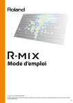
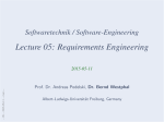
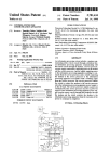
Stage Tec Professional Digital Audio-Routing And Mixing-Console Systems
2010-06-05 © Stage Tec Entwicklungsgesellschaft für professionelle Audiotechnik mbH, Berlin
Stage Tec’s newly designed NEXUS 8-channel
microphone A/D converter now digitizes analog
input signals with a resolution of up to 32 bits. It
processes input levels of up to 24 dBu without
clipping, offering an outstanding dynamic range of
158 dB(A)! This A/D converter does not limit the
microphone dynamics since the digital 32-bit signal includes the entire dynamic range of the microphone, making gain adjustments or analog preamplification of the microphone signal unnecessary.
If subsequent processing is performed at a
lower resolution, the control program allows for
setting a digital gain of up to 70 dB.
The aim of providing optimum audio quality has
been achieved thanks to Stage Tec’s patented
XMIC
XMIC+04 Microphone-Input Board
TrueMatch technology: The input stage is incorporated on the 32-bit converter while all other signal
processes such as subsonic filtering, phase inversion, clip limiting, and gain settings are performed
solely on the digital domain.
Each of the XMIC converters provides four split
outputs with separately adjustable gain and subsonic filters for different downstream consumers.
The XMIC’s space requirements on the base
device are exceptionally low: The board—which is
just 3 U in height—contains eight quality converters. The board itself has a mounting depth of just
4 HP (about 20 mm); however, the XLR standard
ports require 16 HP. Therefore, in addition to the
XLR unit, versions featuring RJ 45 and D-Sub terminals with a footprint of just 4 HP are available for
stationary installations. Thus, a single 3-U base
may accommodate up to 160 of those quality microphone inputs.
XMIC+
• 8 channels on 3 U x 4 HP
• Integrated split amplifier (option)
• 32-bit TrueMatch converters
• Dynamic range: 158 dB(A)@24 dBu (typ.)
• THD&N.: <0.003%@24 dBu
• Negligible converter inaccuracies
• Optimized aliasing rejection
• True galvanic isolation using transformers
• Ultra-low latency/exceptional pulse fidelity
• Auto-mute function when connecting/disconnecting the microphone
Stage Tec TrueMatch Technology
The exceptional XMIC specifications could be
achieved thanks to the TrueMatch principle, a patented converter technology of the latest generation. First-class analog circuit design and state-ofthe-art DSP technology form the basis of these
new reference converters. Unlike conventional dynamic-enhancement techniques such as gain
ranging, TrueMatch does not switch between a
number of conversion curves. Typical side effects
caused by switchover (e.g. suddenly changing
noise levels) do not exist with TrueMatch converters.
Minimized Conversion Errors TrueMatch A/D
converters offer a permanent sample-based correction, resulting in a stable, almost perfect conversion curve with a minimum of errors over the
entire conversion range.
User Manual
Ultra-Low THD TrueMatch A/D converters feature ultra-low THD over a wide level range. This
wide range makes the use of TrueMatch converters uncritical.
Homogenous Noise Spectrum TrueMatch A/D
converters provide a homogenous noise spectrum
over the entire conversion range. The intrinsic
noise is practically not perceptible even at very
low input levels.
Significantly Better Aliasing Suppression Compared to conventional techniques, the TrueMatch
technology provides significantly better aliasing
suppression. Crystal-clear and transparent recording is now ensured even at the usually slightly critical sample rate of 44.1 kHz.
XMIC – 467
Stage Tec Professional Digital Audio-Routing And Mixing-Console Systems
Transformer-Isolated Input Stage
Data
Isolator
Power
DC/DC
Isolator
in addition, the input capacitance is very low, and
the board achieves optimum balancing.
DSP
Power
Businterface
Input Stage &ADC
THD&N at high output levels and low frequencies;
NEXUS Busses
Like all analog system inputs, the XMIC inputs
are transformer-isolated and balanced, offering
true galvanic isolation. The XMIC technology is insusceptible to magnetic fields and provides low
ADC Board
Fig.: Principle of true transformer isolation without a problematic input transformer
Exceptional Dynamics
ry, this range could be represented by a 28-bit resolution; however, the higher resolution of the XMIC
converter also utilizes the noise produced by the
input stage and the connected microphone for
generating “natural” dither, thus reducing the inevitable quantization noise to below the microphone
noise. That is, the intrinsic (microphone/inputstage) noise masks the quantization noise within
the useful signal.
Resulting Converter Features
• The dynamic range of the converter exceeds the
respective values of any conventional microphones.
• The 32-bit resolution covers the entire utilizable
signal – from the noise floor to the microphone-clipping
limit.
• Even very low levels are digitized with high resolution.
• Featuring a maximum input voltage of 24 dBu (@
0 dB gain), the converter can virtually not be overdriven
by typical studio units. Thus, the XMIC can also be used
as a fully adequate line-input unit.
• Gain and signal-processing settings are made on the
digital domain after the A/D conversion, therefore not
affecting the signal quality. Because of their floatingpoint arithmetic capabilities, Stage Tec consoles can
fully utilize the dynamic range, so gain settings are
made only with regard to the target medium.
The World of 24-Bit Digital Signals
Depending on the standard used, digital audio
signals are transmitted with a word length of 24
bits (AES/EBU, MADI) or less. In theory, the 24-bit
resolution provides for a dynamic range of about
144 dB.
As the XMIC’s converter dynamics is much better than that of the downstream digital medium,
the board provides a gain function. The maximum
adjustable gain is 70 dB.
The above theoretical approach of recording
the unprocessed signal with full 32-bit resolution
468
and putting off the gain setting to the post-processing stage is hard to implement in practice due
to the prevailing use of 24-bit formats. In order to
avoid this limitation, highly dynamic signals might
be recorded to separate tracks: the unamplified
converter signal goes to one track while another
one is fed from a split output of the same converter configured with a fixed gain setting. Depending
on the signal level, the alternative track can still be
used for processing fortississimo or pianississimo
signals.
NEXUS – Digital Audio-Routing and Interconnect System
2010-06-05 © Stage Tec Entwicklungsgesellschaft für professionelle Audiotechnik mbH, Berlin
The intrinsic noise of the XMIC input stage is
–133,6 dBu(A), which is less than the noise produced by a 200-ohm resistance! (This value was
determined at a source impedance of 0 ohm to ensure that the converter quality and not the connected source is measured. Complex measuring
setups are required for determining those extremely low voltages to make sure that measuring
errors due to external influence are largely ruled
out. Any stray pickup—or even cable noise—would
affect the measurement. Therefore, the source impedance must be located immediately on the
shielded XLR input jack.)
As the total noise level of the input stage and
the converter is below that produced by an Ohmic
resistance, the noise floor produced by the microphone impedance (about –128 dBu depending on
the actually used microphone) predominates the
overall signal. Moreover, the noise floor produced
by the condenser-microphone amplifier is not yet
considered! Thus, the dynamic range achievable
using the XMIC mostly depends on the intrinsic
noise of the microphone used.
The maximum input level that board can handle
without clipping is 24 dBu. Such “line” signals can
be directly applied to the XMIC—a pad function as
it is needed by other microphone amplifiers/converters is not required here.
The key specifications indicate a dynamic
range of 157.6 dB for the XMIC converter. In theo-
Target Formats
16-bit target system Due to the provided gain
function, the converter can also be used for recording to low-resolution media. For example,
when recording to a 16-bit machine, the gain must
be set appropriately to utilize the limited 16-bit dynamic range of (in theory) 96 dB. Usually, very little or no headroom at all will typically be set during recording to optimally utilize this low resolution. 16-bit formats make sense only for creating
consumer target formats; however, the conversion
should be the last step in the process. Creating
16-bit recordings for serious post-processing is
basically questionable.
20-bit target system A 20-bit resolution provides a dynamic range of 120 dB. Gain is less criti-
cal here: There is still an effective dynamic range
of 100 dB even at a headroom of 20 dB.
24-bit target system When using 24-bit resolution, the resulting dynamic range of 144 dB already exceeds the dynamic range of the microphone. The signal fed from the microphone can be
recorded with no extra processing. Gain settings,
equalization, and even the use of a subsonic filter
can be postponed to the post-recording stage.
Digital clipping spoiling recordings is now over and
done with—perfect for live recording, live interviews and reports, and theaters; not to mention
OB vans.
Processing on the Digital Domain
The combination of extensive dynamics and
the converter principle allows for moving all signal-affecting filtering typical of microphone
preamps to the digital domain. For example, subsonic filters (20, 40, 60, or 80 Hz, 18 dB/oct.) can
be accurately computed and precisely applied;
since they are not contained in the sensitive analog part of the signal path, they do not cause any
audio deterioration.
The recommended way of operation is to
record the input audio directly to a hi-resolution
medium while not altering the original level. All
signal processing including level changes occurs
in a non-destructive way only after recording.
However, as not all environments support this approach, the converters include an adjustable gain
function. This can be set between 0 and 70 dB and
is made on the digital domain, too.
Limiter
To avoid clipping of amplified signals, each
splitter output features an extra on-board limiter
that can also be disabled. This ultra-fast limiter
(fixed settings; attack time: 0 samples) responds
at a level of only –0.06 dBFS, so audio signals will
not be affected at normal working levels.
Split Out System
Lo Cut Filter
Phase
Gain
Limiter
Chn 1
Out A
Lo Cut Filter
Phase
Gain
Limiter
Chn 1
Out B
Lo Cut Filter
Phase
Gain
Limiter
Chn 1
Out C
Lo Cut Filter
Phase
Gain
Limiter
Chn 1
Out D
+48 V
TrueMatch ADC
NEXUS Busses
XMIC
Businterface
2010-06-05 © Stage Tec Entwicklungsgesellschaft für professionelle Audiotechnik mbH, Berlin
Perfectly Integrated Splitter Function
A/D
Channel 1
Oscillator
Channel 2
Channel 8
Fig.: Each of the eight XMIC converters offers four separate outputs with individually adjustable parameters.
User Manual
XMIC – 469
XMIC
Stage Tec Professional Digital Audio-Routing And Mixing-Console Systems
Stage Tec Professional Digital Audio-Routing And Mixing-Console Systems
The splitter function requires
the NEXUS Matrix 5 control
software or later.
The XMIC is the first unit incorporating a splitter directly on the board. The converted signal is
forwarded via four separate outputs to the NEXUS
TDM bus and can thus be made available to four
different consumers. Signal processing is made individually for each of those paths. (Of course, the
signal can still be made available to other consumers using the standard crosspoint routing.)
In the past, the various consumers of a microphone source had to agree upon common settings
for converter gain and filters. For example, changing the gain at one workplace affected all consumers. Changes were possible only using the internal
processing functions of the console or by mutual
agreement. Now, using the XMIC, the FOH engi-
neer can make other gain and filter settings than
the monitoring engineer or the operator in the OB
van.
In systems, where NEXUS user-rights are implemented, the displayed inputs can be restricted, so
every workplace only accesses “its” sources.
Each of the eight converters on an XMIC supports the splitter function, so the entire board offers 32 outputs. (That is, NEXUS matrix windows
show 32 items. The four splitter outputs of the individual converters have the “A”…“D” extensions.)
Note: Phantom power can be enabled or disabled from each workplace (Boolean OR operation). Naturally, this setting will affect all workplaces.
Auto Mute
It is sufficiently known that the microphone
should not be physically connected to or disconnected from the input jack while the fader is open.
Nevertheless, this happens every day, affecting
the hearing of your colleagues (and sometimes
even the audience) as well as your speakers. The
XMIC puts an end to this problem: An intelligent
circuitry detects whenever the connector is inserted or removed and mutes the signal for an instant.
Variant Types
Stage Tec offers the following A/D converter
variants:
• XAD+ (8-channel version, 24-dBu input level)
• HXAD (8 stereo converters)
Versions and Options
The following XMIC types are available:
Ausführungen
XMIC+
4 XLR ports (3-pole, female) for inputs 1…4; the inputs 5…8 (same configuration) are
located on a separate front panel*
XMIC+-RJ
2 RJ45 ports (for all channels)
XMIC+-DSUB
Optionen
25-pole D-Sub port
The RJ45-ADP adapter PCB is available for connecting signal sources requiring XLR
ports.
* The 8-HP front panel of the board includes four XLR ports for inputs 1 to 4. A second front panel offers inputs 5 to
8 and can be installed, for example, in a (reasonably priced) base-device row without a backplane just below or above
the row containing the XMIC.
With the D-Sub and RJ versions designed for stationary installations, all inputs are contained on a 4-HP front panel.
Instead of simple XLR ports, XLR/1/4" combo ports are implemented on request.
Table: XMIC Versions and Options
TrueMatch RMC
The XMIC microphone-input board is not only
used on the NEXUS routing system but is also implemented on the 24-channel TrueMatch RMC ,
making the outstanding audio quality available to
other applications. (There is also a line-input version of this standalone converter device based on
the XAD A/D converter board by Stage Tec.) Existing (even analog) installations can be easily extended and upgraded:
Remastering The TrueMatch RMC converts the
analog output signal of a multitrack recording ma-
470
chine. This high-quality digital signal is then stored
with a resolution of 24 bits to a modern storage
device.
Music Production The simple converters used
in numerous cheap digital mixing consoles are bypassed by an upstream TrueMatch RMC .
Live Recording Thanks to its compact size, the
TrueMatch RMC can be used “on the spot”. The
sensitive analog microphone signals are connected via very short lines.
NEXUS – Digital Audio-Routing and Interconnect System
2010-06-05 © Stage Tec Entwicklungsgesellschaft für professionelle Audiotechnik mbH, Berlin
Adapter RJ45/XLR
Stage Tec Professional Digital Audio-Routing And Mixing-Console Systems
XMIC
Block Diagram
NEXUS Busses
Channel 1
+48 V
6k8
Pin 2
RF-Cut
Input Stage
Pin 3
TrueMatch ADC
A/D
+48 V
Pin 2
Businterface
Pin 1
DSP
(Gain, Lo-Cut,
Limiter, DC-Filter)
Channel 8
RF-Cut
Input Stage
Pin 3
TrueMatch ADC
A/D
Pin 1
Oscillator
XMIC
8 Channel Microphone ADC
Fig.: XMIC+ schematic diagram
Jumpers and terminals
The PCB does not incorporate any jumpers or
terminals relevant to the user.
2010-06-05 © Stage Tec Entwicklungsgesellschaft für professionelle Audiotechnik mbH, Berlin
Circuit Board
XMIC04
Fig.: XMIC+ PCB
User Manual
XMIC – 471
Stage Tec Professional Digital Audio-Routing And Mixing-Console Systems
Technical Specifications
XMIC04+ Specifications
Inputs
Channel configuration
Subsonic filter
Limiter
Unless otherwise indicated, all specifications are based on the following conditions: All measurements comply with
the IRT standards (“IRT Pflichtenheft 3/2”, issued in July 1982, and “IRT Pflichtenheft 3/5”, issued in October 1990)
and AES standards (AES-17, issued in 1998). Ref. rate: 1 KHz. Sample rate: 48 KHz. Full-scale level: 0 dBFS = 24 dBu
8 channels per board, balanced; floating transformer isolation
XLR-3 (female), gold-plated contacts (XLR-3/1/4" combo socket available on request); or RJ45 port, EN 50173-compliant pinout, for S/STP (CAT5) line; or 25-pole D-Sub port
• Adjustable digital gain
• 48-V phantom power
• Subsonic filter, Phase inversion
• Limiter (fixed settings, requires XCPU08 and Matrix5 software or later)
Switchable between 20/40/60/80 Hz, 18 dB/oct.
Threshold
Attack Time
–0,06 dBFS
0 samples
Hold Time
10 ms
Release Time
0.5 s
Ratio
limit
Input level
24 dBu balanced (max.); unbalanced input signal (up to 24 dBu) with phantom power disabled
Phantom power
11 mA (max.), fused; can be enabled/disabled
Dielectric strength
Frequency response
< ±200 V (common-mode signal, with disabled phantom power)
20…20,000 Hz
< 0.05 dB (< ±0.1 dB typ.)
@ 20 Hz
Input impedance
–3 dB (typ.) (18-dB/oct. slope below, in compliance with IRT specifications)
12.5 kilohm with phantom power disabled
6.4 kilohm with phantom power enabled
Input-impedance CMR
125 dB@50 Hz (typ.)
Gain
105 dB@1 KHz (typ.)
80 dB@20 KHz (typ.)
Up to 70 dB (clickfree digital adjustment in 1-dB steps)
THD&N
0.003%@24 dBu (typ.); <0.004% granted
0.003%@–50…0 dBu (typ.); < 0.004% granted
Dynamic range
>144 dB (RMS) or >147 dB (A), limited by the 24-bit output format
157,6 dB(A) total range
Idle-channel noise
Equivalent input-noise level
–155.5 dBFS CCIR-RMS @ 0-ohm input impedance (typ.)
< –129,5 dBu(A) @ 200 ohm input impedance
< –126 dBu(RMS) @ 200 ohm input impedance
< –115 dBqp CCIR1K @ 200-ohm input impedance
Crosstalk attenuation
> 140 dB ( @ 20…20,000 Hz)
> 170 dB @ 1 KHz (typ.)
HF resistance
> 150 dB @ 20 KHz (typ.)
HF-demodulation resistant according to IRT standards (IRT-Pflichtenheft 3/5) and European standards
A/D conversion
Stage Tec TrueMatch Delta-Sigma converter
Resolution
32 bit, 218 times oversampling
Sample rate
44.1 kHz, 48 kHz, 96 kHz (system-specific)
Latency
395 µs @ 48-KHz sample rate
Power supply
Voltage
+4.75…5.25 V
Operating conditions
Current
Temperature range
1200 mA
0…+50°C
Humidity
90% (max.), non-condensing
Temperature range
–35…+70°C
Humidity
90% (max.), non-condensing
Appearance
Board for 19" module frame; 3 U, 340 mm
Front panel
4/8 HP (20.02 or 40.2 mm x 128.5 mm), version-specific
Slot requirements
Weight
1
0.32 kg
Storage conditions
Physical properties
Table: XMIC04+ Specifications
472
NEXUS – Digital Audio-Routing and Interconnect System
2010-06-05 © Stage Tec Entwicklungsgesellschaft für professionelle Audiotechnik mbH, Berlin
< –133,6 dBu(A) @ 0 ohm input impedance
Pinout
Various board versions with different port configurations are available. With standard ports (XLR ,
1/4"), the pinout complies with the respective
specifications, so prefabricated cabling can be
used. (RJ 45 ports have an EN 50173-compliant wiring; for information on special-purpose solutions
such as D-Sub ports, etc., refer to the figure below.)
2010-06-05 © Stage Tec Entwicklungsgesellschaft für professionelle Audiotechnik mbH, Berlin
Fig.: XMIC+ pinout
User Manual
XMIC – 473
XMIC
Stage Tec Professional Digital Audio-Routing And Mixing-Console Systems