1
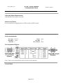
IP Link® Device Interface
Communication Sheet
dba_25_5966_1.pke
Revision: 7/25/2012
This document provides additional assistance with wiring your Extron IP Link enabled product to your device.
Different components may require a different wiring scheme than those listed below.
For complete operating instructions, refer to the user's manual for the specific Extron IP Link enabled product or
the controlled device manufacturer supplied documentation.
Device Specifications:
Device Type:
Manufacturer:
Firmware Version:
Model(s):
Audio Processor
d&b audiotechnik
N/A
REMOTE INTERFACE BRIDGE
Version History:
Driver
Version
1
Date
7/18/2012
IP Link
Compiler
GC
Version
1.5.1
3.3.2
Notes
Initial version.
Driver Notes:
1. The Audio Gain/Attenuation scale of 0 to 127 is equivalent to dB scale of -57.5 to +6 dB.
2. MLC60 Series commands only work with RIB address 1, remote channel address 1.
3. Lock Mode has to be enabled before executing control commands.
Page 1 of 3
IP Link® Device Interface
Communication Sheet
dba_25_5966_1.pke
Revision: 7/25/2012
Control Commands & States:
Audio Gain/Attenuation 1-2 0 to 127 in steps of 1
(Discrete)
Audio Mute 1-2
Toggle
Lock Mode
Toggle
Power Control
Toggle
Remote Channel
1-12
RIB Address
1-8
Status Available:
Audio Gain/Attenuation 1-2 0 to 127 in steps of 1
(Discrete)
Audio Mute 1-2 Status
On
Off
Connection Status
Connected
Disconnected
Device Status
Abnormal Standby
External Error (Standby
Mode)
Temperature abnormality
(Standby mode)
Status Unavailable
Lock Mode Status
On
Off
Status Unavailable
Power Status
On
Off
Status Unavailable
MLC60 Series Supported Commands:
Audio Mute 1-2
Toggle
Lock Mode
Toggle
Power Control
Toggle
Page 2 of 3
Status Unavailable
Temperature warning
dba_25_5966_1.pke
IP Link® Device Interface
Communication Sheet
Cable and Adapter Requirements:
F/M DB9 RS232 null modem serial cable.
Notes for the Device:
See user manual for configuring the device DIP switches for RS232 control.
Serial communication:
Port Type: RS-232
Baud Rate: 19200
Data Bits: 8
Parity: None
Stop Bits: 1
Flow Control: None
Pin Assignments Diagram:
Note: Captive screw connector may also be used as a serial connection.
General Notes:
Page 3 of 3
Revision: 7/25/2012