1
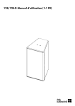
10AL/10AL-D Manual (1.2 EN)
General information
10AL/10AL-D Manual
Version: 1.2 EN, 05/2011, D2611.EN .01
Copyright © 2011 by d&b audiotechnik GmbH; all rights
reserved.
Keep this manual with the product or in a safe place
so that it is available for future reference.
When reselling this product, hand over this manual to the new
customer.
d&b audiotechnik GmbH
Eugen-Adolff-Strasse 134, D-71522 Backnang, Germany
T +49-7191-9669-0, F +49-7191-95 00 00
[email protected], www.dbaudio.com
Contents
d&b 10AL/10AL-D Manual (1.2 EN)
1.
Safety precautions......................................................... 4
1.1. Information regarding the use of loudspeakers......... 4
2.
10AL/10AL-D loudspeaker.........................................
2.1. Product description......................................................
2.2. Connections.................................................................
2.3. Operation....................................................................
2.3.1. Controller settings....................................................
2.4. Dispersion characteristics............................................
2.5. Technical specifications...............................................
3.
Manufacturer's Declarations................................... 11
3.1. EU conformity of loudspeakers (CE symbol)........... 11
3.2. WEEE Declaration (Disposal).................................. 11
5
5
6
7
8
9
9
3
1. Safety precautions
1.1. Information regarding the use of loudspeakers
Potential risk of personal injury
Never stand in the immediate vicinity of loudspeakers driven at a
high level. Professional loudspeaker systems are capable of
causing a sound pressure level detrimental to human health.
Seemingly non-critical sound levels (from approx. 95 dB SPL) can
cause hearing damage if people are exposed to it over a long
period.
In order to prevent accidents when deploying loudspeakers on the
ground or when flown, please take note of the following:
– When setting up the loudspeakers or loudspeaker stands,
make sure they are standing on a firm surface. If you place
several systems on top of one another, use straps to secure
them against movement.
– Only use accessories which have been tested and approved
by d&b for assembly and mobile deployment. Pay attention to
the correct application and maximum load capacity of the
accessories as detailed in our specific "Mounting instructions"
or in our "Flying system and Rigging manuals".
– Ensure that all additional hardware, fixings and fasteners used
for installation or mobile deployment are of an appropriate
size and load safety factor. Pay attention to the manufacturers'
instructions and to the relevant safety guidelines.
– Regularly check the loudspeaker housings and accessories for
visible signs of wear and tear, and replace them when
necessary.
– Regularly check all load bearing bolts in the mounting devices.
Potential risk of material damage
Loudspeakers produce a static magnetic field even if they are not
connected or are not in use. Therefore make sure when erecting
and transporting loudspeakers that they are nowhere near
equipment and objects which may be impaired or damaged by an
external magnetic field. Generally speaking, a distance of 0.5 m
(1.5 ft) from magnetic data carriers (floppy disks, audio and video
tapes, bank cards, etc.) is sufficient; a distance of more than 1 m
(3 ft) may be necessary with computer and video monitors.
4
d&b 10AL/10AL-D Manual (1.2 EN)
2. 10AL/10AL-D loudspeaker
2.1. Product description
The 10S, 10A and 10AL and their "D versions" are a family of high
performance 2-way loudspeakers employing a single 10” driver in
a bass-reflex enclosure and different HF sections for a wide range
of installed sound applications. All models are lightweight passive
designs using neodymium drivers and large horns for accurate
pattern control.
The 10AL and 10AL-D loudspeakers are the line array modules of
this family. They provide constant directivity HF line sources with
either 75° or 105° horizontal coverage using dual 1” exit drivers.
The cabinets are equipped with an integrated rigging system for
the design of vertical arrays providing application specific
dispersion characteristics.
With a frequency response extending from 60 Hz to 18 kHz, the
cabinets can be used as full range systems or supplemented by
different subwoofers of the xS- or xA-Series.
The enclosures are constructed from marine plywood with an
impact resistant black paint finish. The fronts of the cabinets are
protected by a rigid metal grill backed by an acoustically
transparent foam.
The cabinets are Ball Impact Resistant according to DIN 18032-3.
Rigging components
10AL/10AL-D cabinets are connected to form a vertical array
each using the Z5417 Connector plates 10AL. Possible splay
angle settings between adjacent cabinets are 0°, 1°, 2°, 4°, 6°,
9°, 12° and 15°. A vertical array may consist of up to 9 cabinets.
Up to two 18A or 27A subwoofers can be integrated into the
array limiting the maximum number of 10AL/10AL-D cabinets to 6.
Vertical arrays are supported using the Z5414 Flying bar xA and
a pair of Z5413 Flying bar connector plates xA.
Fig. 1: 10AL loudspeaker
Rigging examples:
10AL Line array, 8 deep, with Z5415 Flying bar adapter xA, Z5414 Flying bar xA,
Z5413 Flying bar connector plate xA and Z5417 Connector plate 10AL.
Ground stack consisting of 10AL and 27A-SUB loudspeakers with
Z5417 Connector plate 10AL and Z5418 Connector plate xA-SUB.
d&b 10AL/10AL-D Manual (1.2 EN)
Note: For approved configurations as well as safety and
mounting instructions, refer to the respective rigging manual.
Cabinet options
The weather resistant version (WR) is suitable for outdoor use
(IP34, vertical aiming up to +15°). The cabinets have an impact
and weather protected black PCP (Polyurea Cabinet Protection)
finish.
5
2.2. Connections
The cabinets are fitted with a pair of NL4 connectors and a two
pole screw terminal block (ST). All four pins of both NL4
connectors are wired in parallel. The cabinets use the pin
assignments 1+/1–. Pins 2+/2– are designated to active
subwoofers.
Cabinets with the weather resistant option (WR) are equipped with
a fixed input cable (PG type, H07-RN-F, 2 x 2.5 mm2 (AWG 13),
standard length 5.5 m (18 ft).
Fig. 2: Connector wiring
Pin equivalents of the applicable connector options are listed in the
table below.
NL4
1+
1–
2+
2–
ST
+
–
n.a.
n.a.
PG
Brown (+)
Blue (–)
n.a.
n.a.
Fixed cable connection
The 10AL and 10AL-D loudspeakers are each supplied with a
cover plate [1] and a rubber grommet feed through [2]. For
indoor operation, these items can be used to hide the connector
panel, if required. For unprotected outdoor operation, the
connector panel must be covered, i.e. both items must be used to
achieve an IP degree of protection of IP34.
To install the fixed cable connection, proceed as follows:
Fig. 3: Cover plate and rubber grommet
Tools required: Philips screw driver (#PH2).
1. Prepare the rubber grommet and the connection cable.
2. Remove the knockout opening in the cover plate and attach
the rubber grommet correspondingly.
3. Insert the connection cable through the rubber grommet and
connect the cable wires to the screw terminal.
Þ Observe the correct polarity!
4. Undo the four screws of the connector panel.
5. Push the cover plate towards the connector panel until it fits
into place.
6. Finally fix the cover plate together with the connector panel
using the four screws.
Fig. 4: Installing the fixed cable connection
6
d&b 10AL/10AL-D Manual (1.2 EN)
NL4 connection with cover plate
The two NL4 connector sockets of the cabinet's connector panel
are located in a recess to allow the use of the cover plate [1]
together with NL4 cable connectors, as shown in the graphic
opposite.
Note: Neutrik NL4FC type connectors must be used for this
option.
The cover plate is equipped with two knockout openings to allow
daisy chaining of the loudspeaker.
Fig. 5: NL4 cable connection with cover plate [1]
To use the NL4 connection, proceed in the same manner as
described above in the section entitled Þ "Fixed cable connection"
on page 6.
2.3. Operation
NOTICE!
Only operate d&b loudspeakers with a correctly configured d&b
amplifier, otherwise there is a risk of damaging the loudspeaker
components.
Operation with D6 or D12
Select the controller setup 10AArc or 10ALin for 10AL
loudspeakers.
Select the controller setup 10ADArc or 10ADLin for 10AL-D
loudspeakers.
Within the D12 amplifier they are available in "Dual Channel" or
"Mix TOP/SUB" mode. For combinations with active subwoofers
fed by a single 4-wire cable "Mix TOP/SUB" mode must be
selected.
Up to a total of three 10AL or 10AL-D loudspeakers can be driven
by each channel of the D6 or D12 amplifiers.
"Arc" and "Line" setups
The selection of "Arc" or "Line" depends on the curvature of the
array. Both setups may be used within one array.
The "Arc" setup is intended for line array loudspeakers when used
in curved array sections.
The "Line" setup is used for long throw array sections with three or
more consecutive splay settings of 0°, 1°, 2° or 4. Compared to
the "Arc" setup, the upper mid range is reduced to compensate for
the extended near field.
The transition from "Line" to "Arc" configuration within the array is
made according to the splay progression but may allow for certain
deviations due to the wiring of the cabinets in groups of up to
three.
d&b 10AL/10AL-D Manual (1.2 EN)
7
2.3.1. Controller settings
For acoustic adjustment the functions CUT, HFC and CPL can be
selected.
CUT circuit
Set to CUT, the cabinet low frequency level is reduced. The
cabinets are now configured for use with d&b active subwoofers.
HFC circuit
Selecting the HFC (High Frequency Compensation) circuit
compensates for loss of high frequency energy due to absorption
in air when loudspeakers are used to cover far field listening
positions.
The HFC circuit has two settings (HFC1, HFC2) for different
distance ranges the cabinets have to cover. The settings should be
used selectively, only for those cabinets covering the respective
distances, HFC1 for distances larger than 25 m (80 ft) and HFC2
for distances larger than 50 m (160 ft).
Fig. 6: Frequency response correction of HFC circuit
The compensation is adjusted for a typical relative humidity of
40 %. With lower humidity the absorption by air increases
therefore the distances where the respective HFC setting provides a
correct equalization are shorter than indicated above.
Using the HFC function provides the correct sound balance
between close and remote audience areas, whilst all amplifiers
driving the array can be fed with the same signal.
CPL circuit
The CPL (Coupling) circuit compensates for coupling effects
between the cabinets of an array. CPL begins gradually around
1 kHz, with the maximum attenuation below 200 Hz. As coupling
effects increase with the length of the line array, the CPL circuit can
be set to dB attenuation values between 0 and –9. With higher
attenuation values the corner frequency of the filter shifts towards
lower values.
Positive CPL values create an adjustable low frequency boost (0 to
+5 dB) and can be set when the system is used in full range mode
without subwoofers.
Fig. 7: Frequency response correction of CPL circuit
8
Note: Make sure that all cabinets within the line array are
operated with the same CPL setting.
d&b 10AL/10AL-D Manual (1.2 EN)
2.4. Dispersion characteristics
The following graphs show dispersion angle over frequency of a
single cabinet plotted using lines of equal sound pressure (isobars)
at –6 dB and –12 dB.
10AL
Fig. 9: Isobar diagram vertical
Fig. 8: Isobar diagram horizontal
10AL-D
Fig. 10: Isobar diagram horizontal
Fig. 11: Isobar diagram vertical
2.5. Technical specifications
10AL/10AL-D system data
Frequency response (–5 dB standard)
60 Hz - 18 kHz
Frequency response (–5 dB CUT mode)
110 Hz - 18 kHz
Max. sound pressure 1 m, free field)
10AL with D6/D12
130 dB/133 dB
10AL-D with D6/D12
129 dB/132 dB
(SPLmax peak, pink noise test signal with crest factor of 4)
Input level (100 dB-SPL/1 m)
–16 dBu
Fig. 12: 10AL frequency response, standard and CUT modes
d&b 10AL/10AL-D Manual (1.2 EN)
9
10AL/10AL-D loudspeaker
Fig. 13: 10AL-D frequency response, standard and CUT modes
Nominal impedance
12 ohms
Power handling capacity (RMS/peak 10 ms)
200/1200 W
Nominal dispersion angle (horizontal) 10AL
75°
Nominal dispersion angle (horizontal) 10AL-D
105°
Splay angle setting
0°, 1°, 2°, 4°, 6°, 9°, 12°, 15°
Components
10“ driver with neodymium magnet
2 x 1” exit compression drivers
Passive crossover network
Connections
2 x NL4
2
1 x screw terminal (ST - up to 4 mm /AWG 11)
Optional fixed cable (PG):
H07-RN-F, 2 x 2.5 mm2 (AWG 13), 5.5 m (18 ft)
Pin assignment
NL4: 1+/1–
Fixed cable (PG): brown + / blue –
Weight
14 kg (31 lb)
Fig. 14: 10AL/10AL-D cabinet dimensions in mm [inch]
10
d&b 10AL/10AL-D Manual (1.2 EN)
3. Manufacturer's Declarations
3.1. EU conformity of loudspeakers (CE symbol)
This declaration applies to:
d&b 10AL loudspeaker, Z1557
d&b 10AL-D loudspeaker, Z1558
manufactured by d&b audiotechnik GmbH.
All production versions of these types are included, provided they
correspond to the original technical version and have not been
subject to any later design or electromechanical modifications.
We herewith declare that said products are in conformity with the
provisions of the respective EC directives including all applicable
amendments.
A detailed declaration is available on request and can be ordered
from d&b or downloaded from the d&b website at
www.dbaudio.com.
3.2. WEEE Declaration (Disposal)
Electrical and electronic equipment must be disposed of separately
from normal waste at the end of its operational lifetime.
Please dispose of this product according to the respective national
regulations or contractual agreements. If there are any further
questions concerning the disposal of this product, please contact
d&b audiotechnik.
d&b 10AL/10AL-D Manual (1.2 EN)
11
www.dbaudio.com
D2611.EN .01, 05/2011 © d&b audiotechnik GmbH