1
1
IDS X64 LCD Keypad User Manual 700-411-01C Issues August 2010
2
IDS X-series LCD Keypad User Manual 700-411-01D Issued August 2010
Contents
1.
Introduction to the IDS X-Series LCD Digital Keypad .............................................................. 7
2.
Viewing Violated Zones ............................................................................................................ 7
3.
3.1
3.1.1
3.1.2
3.2
3.2.1
3.2.2
3.3
3.4
3.5
Arming the Control Panel ......................................................................................................... 8
Away Arming ............................................................................................................................ 8
How to Away Arm .................................................................................................................... 8
Quick Away Arm - Shortcut Key ............................................................................................... 8
Stay Arming ............................................................................................................................. 8
How to Stay Arm ...................................................................................................................... 9
Quick Stay Arm - Shortcut Key ................................................................................................ 9
How to Stay Arm and Go ....................................................................................................... 10
Key-Switch or Remote Arming (If fitted) ................................................................................. 10
Auto Arming ........................................................................................................................... 10
4.
4.1
4.2
Disarming the Control Panel .................................................................................................. 11
How to Disarm with a User Code........................................................................................... 11
How to Disarm using a Key-Switch or Remote ...................................................................... 11
5.
5.1
Bypassing Zones ................................................................................................................... 11
How to Bypass / Un-bypass a Zone ...................................................................................... 11
6.
6.1
6.2
6.3
6.4
Emergency Alarms ................................................................................................................ 12
Fire Alarms............................................................................................................................. 12
Panic Alarms .......................................................................................................................... 12
Medical Alarms ...................................................................................................................... 12
Duress Alarms ....................................................................................................................... 13
7.
7.1
Alarm Memory ....................................................................................................................... 13
Event Log............................................................................................................................... 13
8.
8.1
8.2
8.3
8.3.1
8.3.2
8.3.3
8.3.4
8.3.5
8.3.6
8.3.7
8.3.7.1
8.3.7.2
8.3.7.3
8.3.7.4
8.3.7.5
8.3.7.6
8.3.7.7
8.3.8
8.3.9
User Codes............................................................................................................................ 14
Adding, Deleting and Editing User Codes ............................................................................. 14
How to Enter the User Program Mode................................................................................... 15
Explanation of Programmable Options .................................................................................. 15
Option 0 - Add a New User Code .......................................................................................... 15
Option 1 - Edit a Selected User Code ................................................................................... 15
Option 2 - Delete User Code (Code known) .......................................................................... 16
Option 3 – Add/Edit Code...................................................................................................... 16
Option 4 - Delete a User Code ("Slot" known)........................................................................ 16
Option 5 - View a User Code Slot Number ............................................................................ 17
Option 10 - User Code Properties ......................................................................................... 17
Master User ........................................................................................................................... 18
Duress Code.......................................................................................................................... 18
Maid‟s Code .......................................................................................................................... 18
Arm ........................................................................................................................................ 18
Disarm ................................................................................................................................... 18
Global Arm / Disarm Code..................................................................................................... 19
Programmable Output Code ................................................................................................. 19
Option 11 - Assign User Code to Partitions ........................................................................... 19
Option 13 – User Outputs ...................................................................................................... 19
IDS X-series LCD Keypad User Manual 700-411-01D Issued August 2010
3
8.3.10
8.3.11
8.3.12
8.3.13
8.3.14
Option 14 – User Reporting Codes Enable ........................................................................... 20
Option 15 – User Reporting Code Telephone Modules ......................................................... 21
Option 30 - Edit a Zone Name ............................................................................................... 22
Option 40 - Edit the Time ....................................................................................................... 23
Option 41 - Edit the Date ....................................................................................................... 23
9.
9.1
9.2
Stay Zones ............................................................................................................................. 23
How to Select a Stay Profile ................................................................................................... 24
How to Program / Cancel Stay Zones ................................................................................... 24
10.
10.1
Buzz Zones ............................................................................................................................ 24
How to Program / Cancel Buzz Zones ................................................................................... 25
11.
11.1
Chime Zones ......................................................................................................................... 25
How to Program / Cancel Chime Zones ................................................................................ 25
12.
Viewing Trouble Conditions ................................................................................................... 26
13.
Changing a Partition .............................................................................................................. 26
14.
Output Control via a Keypad ................................................................................................. 27
Tables
Table 1: User Programming Options ......................................................................................................... 14
Table 2: User Code Properties .................................................................................................................. 18
Table 3: Output Address Physical Mapping Data ..................................................................................... 20
Table 4: Output Actions Data .................................................................................................................... 20
Table 5: Enable User Reporting Codes ..................................................................................................... 21
Table 6: Specify which Telephone Module to use ..................................................................................... 21
Table 7: Trouble Conditions ...................................................................................................................... 26
4
IDS X-series LCD Keypad User Manual 700-411-01D Issued August 2010
IDS X-series LCD Keypad User Manual 700-411-01D Issued August 2010
5
6
IDS X-series LCD Keypad User Manual 700-411-01D Issued August 2010
Section: 1
1.
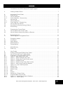
Introduction to the IDS X-Series LCD Digital Keypad
This elegant and user friendly LCD Keypad will allow you easy ac cess to your security system‟s functions
and information at the touch of a button. The 32-character screen will display menus and messages to
guide you through the system‟s operation, so please read this manual carefully, and have your Installer
explain basic system operation.
2.
Viewing Violated Zones
Hold down [MODE] until the beep,
then enter [4] [*] [DISPLAY OPTION] [*]
There are two ways in which to view violated zones in real time. The first is the standard way that has the
scrolling text. This way will say “P(partition number) Ready to Arm” if there are no violated zones,
otherwise, it will display “V(zone Number) (zone name)” for about 3 seconds for each violated zone.
EXAMPLE:
If there are no zone violations, the keypad will alternate flashing between
P1 Ready to Arm
and
P1 Ready
10:01
If there is a zone violation, the keypad will alternate flashing between
P1 Not Ready
and
P1 Not Rdy 10.01
with
V05 Zone 05
flashing underneath.
NOTE:
P1 indicates the partition number.
V05 indicates the zone number that has been violated.
10:01 indicates the time.
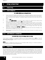
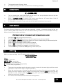
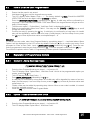
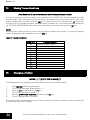
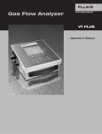
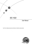
The other way mimics the LED keypad. It displays both the normal and violated zones of 64 zones
simultaneously. A centred dot will represent a normal zone, and a full black flashing rectangle will
represent a violated zone.
The above figure shows that zones 2, 23, and 24 have been violated.
The display options are [1] for LCD mode with the scrolling text, or [2] for LED mode.
IDS X-series LCD Keypad User Manual 700-411-01D Issued August 2010
7
Section: 3
3.
Arming the Control Panel
3.1
Away Arming
3.1.1
How to Away Arm
[#] [USER CODE] (Leave via Entry/Exit Zone)
1.
Ensure that the LCD display reads „Ready to Arm‟ alongside the partition number being armed. If
not, check that all protected doors and windows are closed and that all movement has ceased in
areas covered by motion detectors. If necessary, bypass any required zones and close the front
door.
2.
3.
Press the [#] key.
Enter a valid [USER CODE]. If an incorrect code is entered, the keypad buzzer will beep three
times. In the event of an error, press the [#] key and re-enter the code.
4.
The ARM LED will come on and the keypad buzzer will sound for the duration of the exit delay.
The LCD display will read „Exit Delay‟ alongside the partition number that is being armed. Any
bypassed zones will be displayed on the LCD display as solid text. Any violated zones will be
displayed on the LCD display as flashing text. To scroll through zones which have been
bypassed or violated use the [PANIC] and [MED] keys.
5.
Leave only via a designated exit route. The panel will away arm at the end of the exit delay, if any
enter/exit zone is violated, e.g. the front door.
6.
Once the panel has armed, the LCD display will read „Armed‟ alongside the partition that has
been armed.
3.1.2
Quick Away Arm - Shortcut Key
(Hold down the [1] key until the keypad buzzer sounds)
If this function is enabled, it is possible to AWAY arm by simply holding down the [1] key. The LCD
display will read „Exit Delay‟ alongside the partition number being armed. The keypad buzzer sounds and
the arming process begins.
NOTE:
If the partition is already STAY armed, this key will initialize AWAY arming. It is therefore possible to
change directly from STAY armed to AWAY armed.
3.2
Stay Arming
Stay arming allows the user to monitor selected perimeter zones and bypass interior zones. The user can
remain on the premises with access to designated areas during the STAY ARM cycle. Any zone that may
be violated accidentally should be programmed as a buzz zone. When violated, a buzz zone will cause
the keypad buzzer to sound for 30 seconds before sounding the siren. Entering a valid user code before
the siren sounds, prevents an alarm condition from being registered and will silence the keypad buzzer
and prevent the siren from sounding.
8
IDS X64 LCD Keypad User Manual 700-411-01C Issues August 2010
Section: 3
To provide greater flexibility the panel caters for the programming of four different STAY PROFILES. Each
STAY PROFILE contains a unique combination of STAY, BUZZ and ALARM zones that cater for a
particular STAY ARM requirement.
EXAMPLE:
PROFILE 1 might be used when the family goes to bed in the evening. In this profile, some interior zones
may be programmed as alarm zones or buzz zones, whereas PROFILE 2 is utilised while watching
television when all interior zones would be bypassed. (See section 9.1 How to Select a Stay Profile.)
3.2.1
How to Stay Arm
[#] [USER CODE] (Do not leave premises)
1.
2.
3.
4.
5.
6.
7.
8.
3.2.2
Select the required STAY PROFILE. (See Section 9.1)
Ensure that the LCD display reads „Ready to Arm‟ alongside the partition number being armed. If
not, check that all protected doors and windows are closed and that all movement has ceased in
the areas covered by motion detectors.
Press the [#] key.
Enter a valid [USER CODE]. If an incorrect code is entered, the keypad will give an error beep. In
the event of an error, press the [#] key and re-enter the [USER CODE].
DO NOT violate the Entry/Exit zone (normally the front door). If the Entry/Exit zone is violated the
system will arm in the AWAY mode.
The LCD Keypad will read „Exit Delay‟, the ARM LED will come on and the keypad buzzer will
sound for the duration of the exit delay.
When the panel arms, any STAY zones will be automatically bypassed. These are displayed on
the LCD display as solid text. Any violated zones will be displayed on the LCD display as flashing
text. To scroll through zones which have been bypassed or violated use the [PANIC] and [MED]
keys.
Ensure that you enter only those areas that are bypassed.
Quick Stay Arm - Shortcut Key
(Hold down the [5] key for 2 seconds until the keypad buzzer sounds)
It is possible to STAY arm by holding down the [5] key until the keypad buzzer sounds. The panel will
immediately arm into stay mode without any exit delay. Holding the [5] key again will toggle between the
4 stay profiles.
The LCD display will read „Stay Armed‟ and will indicate any zones that have been bypassed. One is able
to scroll through the list of bypassed, as well as violated, zones by using the [PANIC] and [MED] keys.
Quick Select Method:
Press the [5] key simultaneously with the [PROFILE NUMBER] and release
1.
2.
3.
4.
5.
Ensure that the Panel is disarmed.
Press the [#] key to clear any previous entries.
Press the [5] key and then simultaneously press keys [1], [2], [3], or [4] – depending on the stay
profile you want to choose – then release both keys.
A beep will sound to indicate successful selection of a profile.
Program STAY and BUZZ zones for the profile (see sections 9 and 10), and/or ARM the profile
(with the [5] key).
IDS X-series LCD Keypad User Manual 700-411-01D Issued August 2010
9
Section: 3
3.3
How to Stay Arm and Go
(Hold down the [6] key for two seconds until the keypad buzzer sounds)
This is a single key arm function, which allows the user to STAY arm and leave the premises.
If a partition is already stay armed, holding down the [6] key initiates an exit delay, thus allowing the user
to leave the premises without disarming. At the end of the exit delay, the partition will re-arm in the same
stay profile it was armed in before the [6] key was held down.
1.
2.
3.4
1.
2.
3.
4.
Make sure all zones are clear. Hold down the [6] key until the keypad buzzer sounds. The LCD
display reads „Exit Delay‟ alongside the partition number being armed. Any zones that have been
bypassed will be displayed on the LCD display as solid text. Any zones that are violated will be
displayed on the LCD display as flashing text. Use the [PANIC] and [MED] keys to scroll through
zones that have been bypassed or violated. The keypad buzzer will sound for the duration of the
exit delay. Only leave via a designated exit route.
At the end of the exit delay, the ARM LED will come on and the display will read „Stay Armed‟. All
stay zones will be bypassed.
Key-Switch or Remote Arming (If fitted)
Ensure that the LCD display reads „Ready to Arm‟ before leaving.
Leave the premises and lock the door.
Activate the remote or the key-switch. A remote can be used to Stay Arm or Away Arm.
The alarm will arm in the away mode.
NOTE:
If a remote control is used, it is advisable to have the siren toot on arm function enabled. This provides
verification that the system has armed.
3.5
Auto Arming
The panel may be programmed to arm automatically at a pre-programmed time. Should the premises be
occupied at the time of auto arming, a valid [USER CODE] entered during the pre-arm delay will
terminate the arming sequence. The pre-arm delay is signalled by an exit beep.
10
IDS X-series LCD Keypad User Manual 700-411-01D Issued August 2010
Section: 4
4.
Disarming the Control Panel
4.1
How to Disarm with a User Code
[#] [USER CODE]
1.
2.
3.
4.
5.
6.
Enter the premises through a designated entry route. Entering via any other route will cause an
alarm.
As soon as the Entry/Exit zone is violated, the entry delay will begin. The keypad buzzer will
sound for the duration of the entry period.
Press the [#] key and enter a valid [USER CODE]. If an error beep occurs, press the [#] key and
re-enter the user code.
Once the system disarms, the ARM LED will turn off and the keypad buzzer will stop sounding.
If no valid user code has been entered prior to the expiry of the entry delay period an alarm
condition will be registered.
If the entry period is too short, have your installer change the entry delay period.
NOTE:
If a strobe (or flashing light) has been installed and an alarm condition is registered, the strobe will
continue flashing after the siren has stopped sounding. Entering a valid [USER CODE] will cancel the
strobe.
4.2
1.
2.
5.
5.1
How to Disarm using a Key-Switch or Remote
Activate the remote or key-switch. (The blue button on the remote, unless otherwise
programmed).
The system will disarm and the remote indicator (if installed) will turn off. If the siren toot on
disarm option is enabled, the siren will provide a double toot when the panel is disarmed.
Bypassing Zones
The term BYPASS is used to describe a zone that has been deactivated; i.e. violation of a
bypassed zone is ignored and will not cause an alarm condition.
Once the system is armed, it is not possible to bypass zones.
All bypassed zones will be automatically cancelled each time the panel is disarmed and must be
re-bypassed before the next arming.
How to Bypass / Un-bypass a Zone
Hold down [9] until the beep,
then enter [USER CODE] [*] [ZONE NUMBER] [*] [*] [#]
1.
2.
3.
4.
Ensure the panel is not armed.
To enter bypass mode, hold down [9] until the beep.
The LCD display reads „User Code + *‟.
Enter the [USER CODE] followed by the [*] key.
IDS X-series LCD Keypad User Manual 700-411-01D Issued August 2010
11
Section: 5
5.
6.
7.
8.
9.
10.
The LCD display reads „Zone Number + *‟.
Enter the [ZONE NUMBER] followed by the [*] key. Alternatively, you can use the [PANIC] and
[MED] keys to scroll through the zones.
[Y] next to the zone number indicates that the zone has been bypassed, whilst [N] indicates that
the zone has not been bypassed.
Press the [*] key to toggle between zones being on and off.
Repeat steps 6-8 to bypass/un-bypass other zones.
Press the [#] key to exit the bypass mode.
NOTE:
Panic zones cannot be bypassed.
6.
Emergency Alarms
6.1
Fire Alarms
(Hold down the [F] key for two seconds until the keypad buzzer sounds)
6.2
If the [F] key is pressed until the keypad beeps (approximately 2 seconds) a FIRE ALARM
condition will be activated. The LCD display reads „Alarm!‟ alongside the relevant partition.
The FIRE ALARM CONDITION may also be triggered by a smoke detector connected to an
appropriately programmed zone.
The siren will sound on and off repeatedly, if programmed, and the FIRE REPORTING CODE will
be transmitted to the monitoring company.
To silence the siren enter a valid [USER CODE].
Panic Alarms
(Hold down the [P] key for two seconds until the keypad buzzer sounds)
6.3
If the [P] key is pressed until the keypad beeps (approximately 2 seconds) a PANIC ALARM
condition will be activated. The LCD display reads „Alarm!‟ alongside the relevant partition
number.
A PANIC ALARM may also be activated using any FIXED PANIC button or a REMOTE PANIC
button (if installed).
If the audible panic option has been selected, the siren will sound. A PANIC ALARM will be
transmitted to the monitoring company.
To silence the siren, enter a valid [USER CODE].
Press the [P] key only in an emergency situation that requires response by emergency
personnel.
Medical Alarms
(Hold down the [M] key for two seconds until the keypad buzzer sounds)
12
If the [M] key is pressed until the keypad beeps (approximately 2 seconds) a MEDICAL ALARM
condition will be activated.
IDS X-series LCD Keypad User Manual 700-411-01D Issued August 2010
Section: 6
6.4
The keypad buzzer will beep 5 times.
A medical reporting code will be reported to the monitoring company.
Duress Alarms
[#] + [DURESS CODE]
7.
This is a special user code that should only be used in the unique situation where an intruder
forces one to disarm the system “under duress”.
When a [DURESS CODE] is entered, the control panel disarms. A Duress Alarm Code (if
programmed) will be reported to the monitoring company.
It is advisable to choose a Duress code that can be easily remembered by everyone.
Alarm Memory
The Alarm Memory displays any zones that were tampered, violated, or bypassed during the last arm
cycle. A flashing ARM LED notifies the user of an Alarm Memory condition. To view the Alarm Memory,
disarm the panel and continue as follows:
(Hold down the [0] key for two seconds until the keypad buzzer sounds)
1.
2.
3.
4.
5.
6.
7.
8.
7.1
Hold down [0] until the keypad buzzer beeps.
The ARM and POWER LEDs will turn off and the keypad buzzer will sound briefly.
Use the [MED] or [PANIC] keys to scroll through the zones violated during the last armed period.
Press the [1] key to return to violated zones.
Press the [2] key to display zones that were bypassed.
Press the [3] key to display which zones were tampered.
Press the [6] key followed by the [*] key to view the event log.
The Alarm Memory is erased at the beginning of each arm cycle.
Event Log
When you view event logs, the LCD display reads as follows:
“HH:MM DD/MM/YYYY”
“eeeeeeeeee p ddd”
Where;
HH:MM = event time
MM-DD- YYYY = event date
eeeeeeeeee = event description
p = partition event occurred in (if applicable)
ddd = event data (if applicable)
1.
2.
3.
The system time and date need to be setup correctly in order for the event log to pull the correct
information. These can be setup in options 40 and 41.
When the event log menu is entered, a reference will be taken of the last event recorded. Any
event prior to this reference may be viewed by scrolling back (with the [MED] key) but if the user
decides to scroll forward (with the [PANIC] key) then just events up to and including this
reference point will be viewable.
If no event is encountered then the second line will appear as
IDS X-series LCD Keypad User Manual 700-411-01D Issued August 2010
13
Section: 7
4.
5.
“No Event - ---”.
Pressing [6] followed by [*] after the event log viewing is already active will reset the menu to the
most recent event.
Each event description will be followed by two numbered fields if further data is applicable to
describe an event. The first number is the partition number within which the event occurred. The
second number will either be the zone or user number associated with the event type.
Below is an example of how an event will be displayed on the two-line IDS LCD keypad.
“02:00 01/01/2010”
“Violate 2 23”
Translates to: On 1 Jan 2010 at 2AM zone 23 within partition 2 was violated.
NOTE:
The event log will only show the time and date up to the last power up. For a more detailed listing, please
consult your installer.
8.
User Codes
8.1
Adding, Deleting and Editing User Codes
[*] [MASTER CODE] [*] [PROGRAMMABLE OPTION] [*]
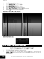
All IDS Alarm Panels utilise a user-friendly programmable interface that allows the user to add, modify, or
delete user codes. See Table 1 for a summary of programmable options. The programmable interface is
accessed by entering the USER PROGRAMMING MODE.
Table 1: User Programming Options
Options
Option 0
Option 1
Option 2
Option 3
Option 4
Option 5
Option 10
Option 11
Option 13
Option 14
Option 15
Option 30
Option 40
Option 41
14
Summary of Programmable Options
Allows for the addition of new user codes.
Allows for the editing of a selected user code.
Note that the user code properties are not edited, only the user code itself.
Allows for the deletion of a user code.
Allows for the adding/editing of the user code slot.
Allows for the deletion of a user code using the user code slot number.
Allows for the viewing of the user code slot number for a selected code.
There are 128 available user code slots.
Allows for the editing of the user code properties for a selected user code.
This is a bitmapped menu.
Allows for the allocation of a selected user code to a designated partition(s).
This is a bitmapped menu.
Allows for the editing of the user outputs
Allows for the user to enable reporting codes.
Allows for the editing of reporting code modules.
Allows for the editing of a zone name
Allows for the editing of the time
Allows for the editing of the date
IDS X-series LCD Keypad User Manual 700-411-01D Issued August 2010
Section: 8
8.2
1.
2.
3.
4.
5.
6.
7.
How to Enter the User Program Mode
Ensure that the panel is not armed.
Hold down the [*] key until the keypad buzzer sounds.
The LCD display reads „Master Code + *‟. The factory default is [1234]. Should the MASTER
USER CODE be set to six digits it will be [123456] by default.
Enter the [MASTER USER CODE], followed by the [*] key. A valid entry will be confirmed by a
long beep. If an invalid MASTER USER CODE was entered, the keypad buzzer will give an error
beep (3 short beeps).
The first menu option – „Option Menu‟, „Add User Code‟ is displayed by default.
Select a programmable option from Table 1. One may use the [PANIC] or [MED] keys to scroll
through the menu options.
Confirm the entry by pressing the [*] key. A valid entry is confirmed by a long beep. An invalid
entry will be signalled by means of an error beep (3 short beeps). If an error beep occurs, press
the [#] key to clear all previous entries, and repeat steps 2 – 6.
EXAMPLE:
To add a new user code, enter User Program Mode by completing steps 2 - 4 as listed above. Menu
Option 0 will be displayed on the LCD screen by default. Press the [*] key to confirm your entry. Once
prompted to „Enter a User Code‟, input a [NEW USER CODE] followed by the [*] key. Once the user
code is programmed, enter the next code followed by [*]. To exit the program mode press the [#] key.
For a full list of options, refer to Table 1. Programming of these options is explained below.
8.3
Explanation of Programmable Options
8.3.1
Option 0 - Add a New User Code
[*] [MASTER CODE] [*] [0] [*] [NEW CODE] [*] [#]
1.
2.
3.
4.
5.
6.
7.
8.3.2
Enter the User Program Mode as per steps 1 - 4 of section 8.2.
The LCD display reads „Option Menu‟, „Add User Code‟. As this is the programmable option you
require, press the [*] key.
The LCD display reads „New Code + *‟.
Enter [NEW USER CODE] followed by the [*] key.
A valid entry is confirmed by a long beep. An invalid entry will be signalled by means of an error
beep (3 short beeps). If an error beep occurs, press the [#] key to clear all previous entries and
repeat steps 1-4.
Further codes can be added by repeating step 4 above. When a user code is added, it is stored
in the first available user slot.
Press the [#] key to exit the User Program Mode.
Option 1 - Edit a Selected User Code
[*] [MASTER CODE] [*] [1] [*] [OLD CODE] [*] [NEW CODE] [*] [#]
1.
2.
Enter the User Program Mode as per steps 1 - 4 of section 8.2.
The LCD display reads „Option Menu‟, „Add User Code‟.
IDS X-series LCD Keypad User Manual 700-411-01D Issued August 2010
15
Section: 8
3.
4.
5.
6.
7.
8.
9.
10.
To select menu option 1 – „Edit User Code‟, press the [1] key or alternatively use the [PANIC] or
[MED] keys to scroll through the list of programmable options until you reach the option you
want.
Press the [*] key.
The LCD display reads „Old Code + *‟.
Enter the [USER CODE] you wish to edit followed by the [*] key.
The LCD display reads „New Code + *‟.
Enter the [NEW CODE] followed by the [*] key. To move the cursor within the NEW CODE, use
the [PANIC] or [MED] keys.
To edit other codes repeat steps 5 - 7.
Press the [#] key to exit the User Program Mode.
8.3.3 Option 2 - Delete User Code (Code known)
[*] [MASTER CODE] [*] [2] [*] [USER CODE] [*] [#]
1.
2.
3.
4.
5.
6.
7.
8.3.4
Enter the User Program Mode as per steps 1 - 4 of section 8.2.
The LCD display reads „Option Menu‟, „Add User Code‟.
To select menu option 2 – „Delete User Code‟, press the [2] key or alternatively use the [PANIC]
or [MED] keys to scroll through the list of programmable options until you reach Menu Option 2.
Press the [*] key.
The LCD display reads „User Code + *‟.
Enter the [USER CODE] to be deleted followed by the [*] key. 'Deleting' the code in slot one will
reprogram it to 1234.
Further codes may be deleted by repeating step 5.
Press the [#] key to exit User Program Mode.
Option 3 – Add/Edit Code
[*] [MASTER CODE] [*] [3] [*] [SLOT NUMBER] [*] [USER CODE] [*] [#]
1.
2.
3.
4.
5.
6.
7.
8.
9.
10.
8.3.5
Enter the User Program Mode as per steps 1 - 4 of section 8.2.
The LCD display reads „Option Menu‟, „Add User Code‟.
To select menu option 3 – „Add/Edit Slot‟, press the [3] key or alternatively use the [PANIC] or
[MED] keys to scroll through the list of programmable options until you reach the option you
want.
Press the [*] key.
The LCD display reads „Slot + *‟.
Enter the [SLOT NUMBER] to be added/edited followed by the [*] key.
The LCD display reads „New Code + *‟, „Slot number‟.
Enter the [USER CODE] followed by the [*] key.
Further slots may be added/edited by repeating steps 6 - 8.
Press the [#] key to exit User Program Mode.
Option 4 - Delete a User Code ("Slot" known)
[*] [MASTER CODE] [*] [4] [*] [SLOT NUMBER] [*] [#]
1.
2.
16
Enter the User Program Mode as per steps 1 - 4 of section 8.2.
The LCD display reads „Option Menu‟, „Add User Code‟.
IDS X-series LCD Keypad User Manual 700-411-01D Issued August 2010
Section: 8
3.
4.
5.
6.
7.
8.
8.3.6
To select menu option 4 – „Delete Slot‟, press the [4] key, or alternatively use the [PANIC] or
[MED] keys to scroll through the list of programmable options until you reach the option you
want.
Press the [*] key.
The LCD display reads „Slot + *‟.
Enter the [SLOT NUMBER] for the User Code you wish to delete followed by the [*] key.
Further User Codes may be deleted by repeating step 5.
Press the [#] key to exit User Program Mode.
Option 5 - View a User Code Slot Number
[*] [MASTER CODE] [*] [5] [*] [USER CODE] [*] [#]
1.
2.
3.
4.
5.
6.
7.
8.3.7
Enter the User Program Mode as per steps 1 - 4 of section 8.2.
The LCD display reads „Option Menu‟, „Add User Code‟.
To select menu option 5 – „View Slot‟, press the [5] key or alternatively use the [PANIC] or [MED]
keys to scroll through the list of programmable options until you reach Menu Option 5. Press the
[*] key.
The LCD display reads „User Code + *‟.
Enter the [USER CODE] followed by the [*] key, the slot number is displayed on the keypad.
Further slot numbers may be viewed by repeating step 5.
Press the [#] key to exit the User Program Mode.
Option 10 - User Code Properties
[*] [MASTER CODE] [*] [1] [0] [*] [USER CODE] [*] [PROPERTY NUMBER] [*] [*] [#]
1.
2.
3.
4.
5.
6.
7.
8.
9.
Enter the User Program Mode as per steps 1 - 4 of section 8.2.
The LCD display reads „Option Menu‟, „Add User Code‟.
To select menu option 10 – „Code Properties‟, press the [1] [0] keys or alternatively use the
[PANIC] or [MED] keys to scroll through the list of programmable options until you reach the
option you want.
Press the [*] key.
The LCD display reads „User Code + *‟.
Enter the [USER CODE] followed by the [*] key.
Enter the [PROPERTY NUMBER] followed by the [*] key, or use the [PANIC] or [MED] keys to
scroll through the User Options that can be assigned to a user.
Pressing the [*] key toggles between [Y] and [N] for the selected user option.
Press the [#] key twice to exit User Program Mode.
EXAMPLE:
To enable a User Code to function as a duress code, when prompted for the option press the [2] key
followed by the [*] key.
IDS X-series LCD Keypad User Manual 700-411-01D Issued August 2010
17
Section: 8
Table 2: User Code Properties
Option
1
2
3
4
5
6
7
Property
Master User
Duress Code
Arm to Disarm Code [Maid‟s Code]
Arm Code
Disarm Code
Global Arm /Disarm
Programmable Output Code
Explanation of User Code Properties
8.3.7.1 Master User
When assigned to a user, this property allows the user to act as a Master User.
8.3.7.2 Duress Code
This is a special 4 (default) or 6-digit user code (check the code length with your installer) and
should only be used in the unique situation where an intruder forces one to disarm the system
"under duress".
When the [DURESS CODE] is entered, the control panel disarms normally - however a DURESS
REPORTING CODE is transmitted to the monitoring company to inform them that you have been
forced to disarm the control panel by an intruder.
It is advisable to choose a code that can be easily remembered by all family (or staff) members.
8.3.7.3 Maid‟s Code
This code can be used to limit access to the premises. A maid‟s code will only disarm the system if the
same code was used for arming. If armed with a code other than this code, the system will view an
attempt to disarm using a maid‟s code as an invalid entry. Any valid user code will disarm the system if it
has been armed with a maid‟s code.
8.3.7.4 Arm
This code will arm the partitions assigned to the user depending on their status. If all partitions are
disarmed, entering a group code will arm all of the assigned partitions. In a case where some partitions
are armed and others disarmed, entering this group code at the keypad of the disarmed partition will arm
the disarmed partitions only.
8.3.7.5 Disarm
This code will disarm the partitions assigned to the user depending on their status. If all partitions are
armed, entering a group code will disarm all of the assigned partitions. In a case where some partitions
18
IDS X-series LCD Keypad User Manual 700-411-01D Issued August 2010
Section: 8
are disarmed and others armed, entering this group code at the keypad of the armed partition will disarm
the armed partitions only.
8.3.7.6 Global Arm / Disarm Code
This code will either arm or disarm the partitions assigned to that user depending on their status. If both
partitions are disarmed, entering a global code will arm both partitions. If more than one partition is
armed, entering a global code will disarm them. In the case where one partition is armed and another is
disarmed, entering a global code at the keypad of the armed partition will disarm that partition and
entering a global code at the keypad of the disarmed partition will arm that partition.
8.3.7.7 Programmable Output Code
Any event, which is able to trigger a programmable output, can be assigned to an output number from 1
to 41. Assigning an event to outputs 1 to 5 will use the panel‟s onboard outputs 1 to 5. Assigning an
event to outputs 6 to 25 will use an output on a zone expander or keypad.
8.3.8
Option 11 - Assign User Code to Partitions
[*] [MASTER CODE] [*] [1] [1] [*] [USER CODE] [*] [PARTITION NUMBER] [*] [*] [#]
1.
2.
3.
Enter the User Program Mode as per steps 1 - 4 of section 8.2.
The LCD display reads „Option Menu‟, „Add User Code‟.
To select menu option 11 – „User ->Partitions‟, press the [1] [1] keys or alternatively use the
[PANIC] or [MED] keys to scroll through the list of programmable options until you reach the
option you want.
Press the [*] key.
The LCD display reads „User Code + *‟.
Enter the [USER CODE] followed by the [*] key.
The partitions to which the [USER CODE] is assigned are indicated by options 1 - 8. If the user is
assigned to partition 1, there will be a YES next to option 1 and the user can thus arm and disarm
partition 1. If the user is assigned to partition 4, there will be a YES next to option 4. It is possible
to program codes to arm/disarm any combination of the available partitions.
Enter the [PARTITION NUMBER] followed by the [*] key. One may also use the [PANIC] and
[MED] keys to scroll through the partitions.
Press the [*] key to toggle between YES and NO.
Repeat steps 8 - 9 until the User Code has been assigned to the correct partition(s).
Press the [#] key twice to exit the User Program Mode.
4.
5.
6.
7.
8.
9.
10.
11.
8.3.9
Option 13 – User Outputs
[*] [MASTER CODE] [*] [1] [3] [*] [USER CODE] [*] [OUTPUT No] [*] [OUTPUT ACTION] [*] [#]
1.
2.
3.
4.
Enter the User Program Mode as per steps 1 - 4 of section 8.2.
The LCD display reads „Option Menu‟, „Add User Code‟.
To select menu option 13 –„User Outputs‟, press the [1] [3] keys or alternatively use the [PANIC]
or [MED] keys to scroll through the list of programmable options until you reach the option you
want.
Press the [*] key.
IDS X-series LCD Keypad User Manual 700-411-01D Issued August 2010
19
Section: 8
5.
6.
7.
8.
9.
10.
11.
12.
The LCD display reads „User Code + *‟.
Enter the [USER CODE] followed by the [*] key.
The LCD display reads „Output No. + *‟.
Enter the [OUTPUT No] followed by the [*] key.
The LCD display reads „Action + *‟.
Enter the [OUTPUT ACTION] followed by the [*] key.
Repeat steps 6 - 10 until all the user outputs have been entered.
Press the [#] key to exit the User Program Mode.
Table 3: Output Address Physical Mapping Data
Address
00
01
02
03
04
05
06
07
08
09
10
11
12
13
14
15
16
17
18
19
20
Physical Outputs
Disabled
Onboard output 1
Onboard output 2
Onboard output 3
Onboard output 4
Onboard output 5
Zone expander 1 output 1
Zone expander 1 output 2
Zone expander 2 output 1
Zone expander 2 output 2
Zone expander 3 output 1
Zone expander 3 output 2
Zone expander 4 output 1
Zone expander 4 output 2
Zone expander 5 output 1
Zone expander 5 output 2
Zone expander 6 output 1
Zone expander 6 output 2
Reserved
Reserved
Reserved
Address
21
22
23
24
25
26
27
28
29
30
31
32
33
34
35
36
37
38
39
40
41
Physical Outputs
Reserved
Reserved
Reserved
Reserved
Reserved
Reserved
Reserved
Reserved
Reserved
Reserved
Reserved
Reserved
Reserved
Keypad 1 output
Keypad 2 output
Keypad 3 output
Keypad 4 output
Keypad 5 output
Keypad 6 output
Keypad 7 output
Keypad 8 output
Table 4: Output Actions Data
Value
00
01
02
03
Output Action
Set Output High (Set)
Set Output Low (Reset)
Pulse Output High
Pulse Output Low
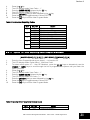
8.3.10 Option 14 – User Reporting Codes Enable
[MASTER CODE] [*] [1] [4] [*] [USER CODE] [*] [BITMAP] [*] [#]
1.
2.
3.
20
Enter the User Program Mode as per steps 1 - 4 of section 8.2.
The LCD display reads „Option Menu‟, „Add User Code‟.
To select menu option 14 – „User RC Enable‟, press the [1] [4] keys or alternatively use the
[PANIC] or [MED] keys to scroll through the list of programmable options until you reach the
option you want.
IDS X-series LCD Keypad User Manual 700-411-01D Issued August 2010
Section: 8
4.
5.
6.
7.
8.
9.
10.
Press the [*] key.
The LCD display reads „User Code + *‟.
Enter the [USER CODE] followed by the [*] key.
The LCD display reads „RC Option + *'.
Enter the [BITMAP] that you want followed by the [*] key.
Press the [*] key to toggle between ON and OFF.
Press the [#] key to exit the User Program Mode.
Table 5: Enable User Reporting Codes
LED
1
2
3
4
5
On / Off
ON
OFF
ON
OFF
ON
OFF
ON
OFF
ON
OFF
Action
Enable close RC
Disable close RC
Enable stay close RC
Disable stay close RC
Enable open RC
Disable open RC
Enable siren cancel RC
Disable siren cancel RC
Enable access RC
Disable access RC
8.3.11 Option 15 – User Reporting Code Telephone Modules
[MASTER CODE] [*] [1] [5] [*] [USER CODE] [*] [BITMAP] [*] [#]
1.
2.
3.
4.
5.
6.
7.
8.
9.
10.
Enter the User Program Mode as per steps 1 - 4 of section 8.2.
The LCD display reads „Option Menu‟, „Add User Code‟.
To select menu option 15 – „User RC Modules‟, press the [1] [5] keys or alternatively use the
[PANIC] or [MED] keys to scroll through the list of programmable options until you reach the
option you want.
Press the [*] key.
The LCD display reads „User Code + *‟.
Enter the [USER CODE] followed by the [*] key.
The LCD display reads „RC Code <*>‟.
Enter the [BITMAP] that you want followed by the [*] key.
Press the [*] key to toggle between ON and OFF.
Press the [#] key to exit the User Program Mode.
Table 6: Specify which Telephone Module to use
LED
1
On / Off
ON
Action
Telephone Module 2
IDS X-series LCD Keypad User Manual 700-411-01D Issued August 2010
21
Section: 8
2
3
4
5
OFF
ON
OFF
ON
OFF
ON
OFF
ON
OFF
Telephone Module 1
Telephone Module 2
Telephone Module 1
Telephone Module 2
Telephone Module 1
Telephone Module 2
Telephone Module 1
Telephone Module 2
Telephone Module 1
NOTE:
The options are only available if the corresponding option in option 14 is on.
EXAMPLE:
If the close RC is disabled, then you will not be able to set the telephone module for it. If it is enabled,
then you can choose between telephone module 1 and 2.
NOTE:
User options 20-29 can be found in the Remote Receiver Manual P/N: 700-408-02A.
8.3.12 Option 30 - Edit a Zone Name
[*] [MASTER CODE] [*] [3] [0] [*] [ZONE No] [*] [*] [ZONE NAME] [*] [#]
1.
2.
3.
4.
5.
6.
7.
8.
Enter the User Program Mode as per steps 1 - 4 of section 8.2.
The LCD display reads „Option Menu‟, „Add User Code‟.
To select menu option 30 – „Edit Zone Name‟, press the [3] [0] keys or alternatively use the
[PANIC] or [MED] keys to scroll through the list of programmable options until you reach the
option you want.
Press the [*] key.
The LCD display reads „Zone Names <*>‟, „Zone Num + *‟.
Enter the [ZONE No] followed by the [*] key.
Press the [*] key to begin entering the zone name. A blinking character indicates that that
character is currently selected for editing.
Enter the [ZONE NAME] followed by the [*] key.
NOTE:
Pressing a key once will display the first letter on the key. Pressing a key twice will display the
second letter on the key etc. Numbers will be displayed once all the letters listed on the key have
been displayed.
The [PANIC] and [MED] keys may be used to scroll right or left through the name respectively.
The [MODE] key is used to toggle between upper and lower case.
Pressing the [#] key will reset the zone name to [Zone Number] if a character has been entered.
If no character has been entered, then pressing [#] will exit zone name programming and return
to the options menu.
9.
10.
Repeat steps 5 - 7 if more zones are to be named.
Press the [#] key to exit the User Program Mode.
NOTE:
When you are at step 6, entering a zone number, you can use the following options to copy or delete a
zone name:
22
IDS X-series LCD Keypad User Manual 700-411-01D Issued August 2010
Section: 8
[0] [*]
[111] [*]
[222] [*]
Copy All – this is used to update the zone names to all keypads connected to the Xseries Alarm Panel. This is used when a keypad has been replaced or a new keypad is
added to the panel. (This can be used when you replace a keypad and want it to display
the existing zone names).
Delete Name – this is used to delete the zone name being viewed from the X-series
Alarm Panel.
Delete All – this option is used to delete all zone names from the X-series Alarm Panel.
8.3.13 Option 40 - Edit the Time
[*] [MASTER CODE] [*] [4] [0] [*] [TIME] [*] [#]
1.
2.
3.
4.
5.
6.
7.
Enter the User Program Mode as per steps 1 - 4 of section 8.2.
The LCD display reads „Option Menu‟, „Add User Code‟.
To select menu option 40 – „Edit Time‟, press the [4] [0] keys followed by the [*] key or
alternatively use the [PANIC] or [MED] keys to scroll through the list of programmable options
until you reach the option you want.
Press the [*] key.
The LCD display reads „New Time?‟.
Enter the [TIME] that you wish to edit, followed by the [*] key. The format is HHMM.
Press the [#] key to exit the User Program Mode.
8.3.14 Option 41 - Edit the Date
[*] [MASTER CODE] [*] [4] [1] [*] [DATE] [*] [#]
1.
2.
3.
4.
5.
6.
7.
9.
Enter the User Program Mode as per steps 1 - 4 of section 8.2.
The LCD display reads „Option Menu‟, „Add User Code‟.
To select menu option 41 – „Edit Date‟, press the [4] [1] keys followed by the [*] key or
alternatively use the [PANIC] or [MED] keys to scroll through the list of programmable options
until you reach the option you want.
Press the [*] key.
The LCD display reads „New Date?‟
Enter the [DATE] that you wish to edit, followed by the [*] key. The format is DDMMYY.
Press the [#] key to exit the User Program Mode.
Stay Zones
Stay zones are those zones that are bypassed automatically when the system is "STAY ARMED". To avoid
triggering the alarm, zones such as bedrooms that are protected by Passive Infra-Red (PIR) detectors or
windows that may be opened, must be bypassed when "staying at home". Stay zones need only be
programmed once. Each time the system is armed in the Stay Mode the pre-selected stay zones will be
bypassed automatically. The panel allows for four unique STAY PROFILES to be stored. A STAY PROFILE
stores a preselected combination of STAY and BUZZ zones to suit a specific STAY ARM requirement. If a
partition is stay armed using Profile 1, it is possible to toggle the panel arm status directly to stay arm
profile 2 by holding the [5] key for two seconds. STAY and BUZZ zones can be programmed for each
profile once the profile has been selected. See sections 9 & 10.
IDS X-series LCD Keypad User Manual 700-411-01D Issued August 2010
23
Section: 9
9.1
How to Select a Stay Profile
[MODE] [2] [*] [PROFILE NUMBER] [*]
1.
2.
3.
4.
5.
6.
7.
9.2
Hold [MODE] down for one second until the keypad beeps twice.
The LCD display reads „Mode Number + *‟.
Press the [2] key followed by the [*] key.
The LCD display reads „Profile + *‟.
Press [1], [2], [3], or [4] for the required profile, followed by the [*] key.
The buzzer will give a long beep.
Program STAY and BUZZ zones for the profile or ARM the profile (See sections 9 & 10).
How to Program / Cancel Stay Zones
[3] [ZONE NUMBER] [*] [#]
1.
2.
3.
4.
5.
6.
Select the required stay profile (See section 9.1)
Hold down the [3] key until the keypad buzzer sounds.
The LCD display read „Zone Number + *.‟
Press the [ZONE NUMBER] corresponding to the zone you wish to be a Stay zone followed by
the [*] key. Alternatively use the [PANIC] or [MED] keys to scroll through the zones.
A [Y] next to a zone number indicates that that particular zone is programmed as a stay zone.
Press the [*] key to toggle between YES and NO.
NOTE:
Buzz zones will be shown by flashing LEDs. (See Section 10). A Buzz zone cannot be selected
as a Stay Zone. The Buzz status must be cleared first.
7.
8.
10.
Repeat steps 4 - 6 until the all the required Stay zones are programmed/cancelled..
Press the [#] key to exit the Stay zone programming mode.
Buzz Zones
Violation of a buzz zone when Stay Armed will cause the keypad buzzer to sound for a period of 30
seconds during which time a valid user code must be entered. If a valid user code is not entered during
this period, the system will register an alarm condition. This feature helps prevent unnecessary false
alarms.
NOTE:
If an Entry/Exit zone is programmed as a buzz zone, violation of the Entry/Exit zone (when the panel is
Stay Armed) will cause the keypad buzzer to sound for the duration of the entry delay time. This, if the
panel is stay armed, allows the user to enter the premises and disarm the panel.
If it is not programmed as a buzz zone, the alarm will be triggered immediately. If the panel was armed
using the [6] key (Stay Arm and Go) violation of the Entry/Exit zone will always start the Entry/Exit delay.
24
IDS X-series LCD Keypad User Manual 700-411-01D Issued August 2010
Section: 10
10.1
How to Program / Cancel Buzz Zones
[4] [ZONE NUMBER] [*] [#]
1.
2.
3.
4.
5.
Select the required Stay Profile. (See section 9.1)
Hold down the [4] key until the keypad buzzer sounds.
The LCD display reads „Zone Number + *‟.
Press the [ZONE NUMBER] corresponding to the zone you wish to be programmed as a Buzz
zone followed by the [*] key. Alternatively use the [PANIC] or [MED] keys to scroll through the
zones.
A [Y] next to the zone number indicates that the zone has been programmed as a Buzz zone.
Flashing text indicates a Stay zone.
Press the [*] key to toggle between YES and NO.
Repeat steps 4 - 6 until all the required Buzz zones are programmed/cancelled.
Press the [#] key to exit the Buzz zone programming mode.
6.
7.
8.
NOTE:
A zone cannot be both a Buzz and Stay Zone.
A Stay zone cannot be selected as a Buzz zone.
11.
Chime Zones
The chime mode allows the user to monitor nominated zones while the system is disarmed. The keypad
buzzer will sound briefly when the nominated zone is violated - the siren will NOT sound and no alarm
condition will be reported.
EXAMPLE:
If you wish to know each time someone enters or exits the front door of your office, program this zone as
a chime zone, the keypad will beep each time someone opens the front door.
11.1
How to Program / Cancel Chime Zones
[2] [ZONE NUMBER] [*] [#]
1.
2.
3.
4.
5.
6.
7.
Hold down the [2] key until the keypad buzzer sounds.
The LCD display reads „Zone Number + *‟.
Press the [ZONE NUMBER] corresponding to the zone you wish to be a Chime zone followed by
the [*] key. Alternatively use the [PANIC] or [MED] keys to scroll through the zones.
A [Y] next to the zone number indicates that the zone has been selected as a Chime zone.
Press the [*] key to toggle between YES and NO.
Repeat steps 3 - 5 until all the required Chime zones are programmed/cancelled.
Press the [#] key to exit the Chime zone programming mode.
IDS X-series LCD Keypad User Manual 700-411-01D Issued August 2010
25
Section: 12
12.
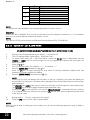
Viewing Trouble Conditions
(Hold down the [7] key for two seconds until the keypad buzzer sounds)
The user is alerted to a trouble condition via the flashing of the POWER LED. It is also possible to enable
a trouble beep. If the trouble beep has been enabled, the keypad buzzer will sound to alert the user that a
trouble condition has occurred. Press the [#] key to silence the buzzer. Hold down the [7] key for two
seconds. The LCD keypad will display what the trouble conditions are. The system will automatically exit
the TROUBLE VIEWING MODE after one minute. Alternately, to exit this mode, press the [#] key.
NOTE:
Certain trouble conditions will only clear once the trouble condition has restored. To cancel the beeping
without viewing the trouble conditions, press the [#] key.
Table 7: Trouble Conditions
Zone LED
1
2
3
4
5
6
7
8
9
10
11
12
13.
Trouble Condition
Panel AC Supply Failure
Panel Communications Failure
Telephone Line Trouble
Siren Tamper
Low Battery
Aux 12V Resettable Fuse Blown
Engineer reset
Box tamper
Peripheral Device Tamper
Peripheral Communications Failure
Peripheral Low Supply Voltage
EEPROM chip failure
Changing a Partition
[MODE] [1] [*] [PARTITION NUMBER] [*]
To change partitions the keypad must be assigned to access the required partition.
1.
2.
3.
4.
5.
6.
Hold [MODE] until the keypad beeps.
The LCD display reads „Mode Number + *‟.
Press the [1] key followed by the [*] key.
The LCD display reads „Partition +*‟.
Enter the [PARTITION NUMBER], followed by the [*] key.
The LCD display reads „P(number)‟.
The keypads may be partitioned to remain in the new partition. Any value outside of these constraints will
result in a key entry error occurring.
26
IDS X-series LCD Keypad User Manual 700-411-01D Issues August 2010
Section: 14
14.
Output Control via a Keypad
[MODE] [3] [*] [OUTPUT NUMBER] [*] [*] [#]
If the panel has been setup to control switching functions via its outputs, these can be controlled via the
keypad - e.g. turning lights on and off.
1.
Hold [MODE] down for one second until the keypad beeps twice.
2.
The LCD display reads „Mode Number + *‟.
3.
Press the [3] key followed by the [*] key.
4.
The LCD display reads „Output Num + *‟.
5.
Enter the [OUTPUT NUMBER] followed by the [*] key.
6.
Press the [*] key to toggle between ON and OFF.
7.
Repeat steps 5 – 6 to program any other outputs.
8.
Press the [#] key to exit.
Ensure that you have checked with your Installer which outputs are used for radio reporting to prevent the
triggering of false alarms.
IDS X-series LCD Keypad User Manual 700-411-01D Issued August 2010
27
28
IDS X-series LCD Keypad User Manual 700-411-01D Issued August 2010
IDS X-series LCD Keypad User Manual 700-411-01D Issued August 2010
29
30
IDS X-series LCD Keypad User Manual 700-411-01D Issued August 2010
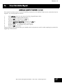
Quick Reference User Guide
Description
Add a User Code
Change a User Code
Delete a User Code (Code Known)
Programming
[*] [Master Code] [*] [0] [*] [New Code] [*]
[*] [Master Code] [*] [1] [*] [Old Code] [*] [New Code] [*]
[*] [Master Code] [*] [2] [*] [User Code] [*]
Add/Edit Slot
[*] [Master Code] [*] [3] [*] [Slot Number] [*] [User Code] [*]
Delete a User Code (Slot Known)
View a Slot Number
[*] [Master Code] [*] [4] [*] [Slot Number] [*]
[*] [Master Code] [*] [5] [*] [User Code] [*]
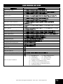
Edit User Code Properties
Allocate a User Code to a Partition
User Outputs
User Reporting Codes Enable
User Reporting Code Telephone
Edit a Zone Name
Edit the Time
Edit the Date
Change Partitions
Select a Stay Profile
Program/Cancel Stay Zone
Program/Cancel Buzz Zone
Program/Cancel Chime Zone
Quick Arm
Quick Stay
Stay Arm and Go
Bypassing/Un-bypassing a Zone
Alarm Memory
View Trouble Conditions
[*] [Master Code] [*] [1] [0] [*] [User Code] [*] [Property
Number] [*] [*]
[*] [Master Code] [*] [1] [1] [*] [User Code] [*] [Partition Number]
[*] [*]
[*] [Master Code] [*] [1] [3] [*] [User Code] [*] [Output Number]
[*] [Output Action] [*]
[*] [Master Code] [*] [1] [4] [*] [User Code] [*] [Bitmap] [*]
[*] [Master Code] [*] [1] [5] [*] [User Code] [*] [Bitmap] [*]
[*] [Master Code] [*] [3] [0] [*] [Zone No] [*] [*] [Zone Name] [*]
[*] [Master Code] [*] [4] [0] [*] [Time] [*]
[*] [Master Code] [*] [4] [1] [*] [Date] [*]
[Mode] [1] [*] [Partition Number] [*]
[Mode] [2] [*] [Profile Number] [*]
[3] [Zone Number] [*]
[4] [Zone Number] [*]
[2] [Zone Number] [*]
[1]
[5]
[6]
[9] [Master Code] [*] [Zone Number] [*] [*]
[0] Displays zones violated.
[7]
1 = AC Mains Fail
2 = No Communication
3 = Phone Line
4 = Siren Tamper
5 = Low Battery
6 = 12V Aux Fuse
7 = Engineer Reset
8 = Box Tamper
9 = Tamper on Peripheral Device
10 = Comms Loss to Peripheral Device
11 = Loss of Power to Peripheral Device
12 = EEPROM Failure
IDS X-series LCD Keypad User Manual 700-411-01C Issues August 2010
31
32
IDS X-series LCD Keypad User Manual 700-411-01D Issued August 2010