1
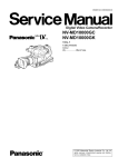
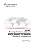
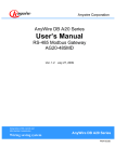
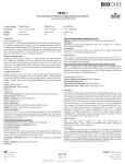
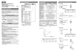
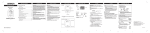
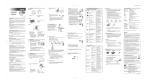
Anywire Corporation
○
R
AnyWire○DB A40 series
AnyWire Bitty series
AnyWire○OpenTerminal series
R
R
Link Connector Insulation
Displacement Method of
Flat Cable
(Additional version)
First version 07 November, 2006
UMA-0A
Caution Items
The cautions to this manual
1. This manual should be sends to last user.
Please perform operation of this product after often reading this manual and understanding the
contents.
2. This manual explains the functional details included in this product, and does not guarantee
suiting a visitor's specific purpose.
3. Reproducing and reproducing some or of this device without notice refuses.
4. It may change without a preliminary announcement about the contents of this manual in the
future.
Warnings
!
WARNING
! CAUTION
"Warning" shows the contents a possibility of getting death or seriously injured is
assumed to be, when handling is mistaken.
"Caution" indicates that the failure to follow this instruction can result in
minor injury or property damage.
In order to use it safely
- An AnyWire system is not a thing having a control function aimed for safe
security.
WARNING
- When as follows, while having care special about safety measures which had a
margin to rating and a function and to be used, such as a way and fail-safe,
carried out, please consult to our company.
!
(1) The use for which high safety is needed
- The use it is predicted to be to have big influence to a human life or
property
- Device for medical treatments, device for safe, etc.
(2) When used for the system by which higher reliability is demanded
- Use to vehicles control, combustion control device, etc.
Please be sure to turn off a system before installation or exchange work.
Please use an AnyWire system within the limits of the specification and the
conditions that were set to this manual.
!
i
CAUTION
Be sure not to turn on the 24V power before completing wiring and connecting
in AnyWire System.
Use a regulated power supply of 24V DC. Non-regulated power supply may
cause a trouble to the system.
Keep transmission cables and I/O cables away from high-voltage and power
cables, though the AnyWire System has high noise margin.
Be careful not to allow metal bits into the unit, the connectors or the terminal
blocks, especially when wiring.
Mis-wiring may cause failure. Consider the length and installation of cable
wiring to keep connectors and cables from disconnecting or excessive
distortion.
Never solder the stranded wire to be connected with the terminal block,
otherwise causing a defective contact.
In case of long cable length of power line along the transmission lines, large
voltage drops will occur and may cause voltage shortage for the distant Slave
Units. In that circumstance, connect the local power supply units so that the
prescribed voltage is secured at each local Slave Unit.
Be careful of the following items about installation environment.
No exposing directly to the sunlight and ambient temperature is 0 to +55 ˚C.
Operating relative humidity is 10 to 90 % and no dew condensation by sudden
temperature change
No corrosive or inflammable gases
No direct vibration or impact
Fasten terminal screws securely to avoid malfunction.
In case of storage of the product, keep away from high temperature and high
humidity. (Storage temperature is –20 to 75˚C.)
When the emergency stop circuit or the interlock circuit for safety is arranged,
provide these circuits outside the AnyWire System.
ii
Contents
1
2
3
4
5
6
7
iii
Introduction
Subject to combination
Insulation Displacement to Flat Cable Terminal
Insulation Displacement to the Intermediate of Flat Cable
Connection
AnyWire System Warranty
Change History
1-1
2-1
3-1
4-1
5-1
6-1
7-1
1 Introduction
Link Connector is an IDC (Insulation displacement contact)-type connector for use as
“adding” or “branching” connections with the same connector combinations for a dedicated
flat-type connector.
Basically, IDC pliers must be used with this connector.
(According to 3M catalog)
However, dedicated tools for Insulation displacement work can be purchased instead of
pliers.
The finish (coupling of housing or contact)may be different depending on the worker’s
experience or the number of processing when using pliers.
For safety we recommend that dedicated tools be used if user is inexperienced, even if
performing multiple processing as shown in this manual.
Please refer to this manual as an additional manual separate from “pliers insulation
displacement work”, a standard work method, introduced in AnyWire Technical manual or
laying Manual.
2 Subject to combination
Flat cable
Link Connector
!
CAUTION
(FK4-075-100 :AnyWire model)
(LP4-BK-10P :AnyWire model)
(38104-0018-000FL : 3M model)
Do not use other than above combination.
Otherwise, connection faire may occur.
※Please confirm specifications and select adaptable link connector for cabtyre before you
use. For more details, refer to the 3Mwebsite.
2-1
3 Insulation Displacement to Flat Cable Terminal
Depending on AnyWire standard identification color, signals of flat cable are assigned as
shown in the table below.
Pin No
(1)
(2)
Signal
Name
DN (Bitty, OpenTerminal)
G (AnyWire DB A40)
Line color
Black
(3)
(4)
0V
24V
White
Green
DP (Bitty, OpenTerminal)
D (AnyWire DB A40)
Red
This coloration and signal relations may be the basis device connection.
(1) Prepare the connector cover.
(2) Close the connector cover when flat cover inserted to the connector cover.
Small Hook
Hinji
Hinji side should be a black line.
3-1
Black
(3) Check the end surface of cable insert connector cover and attach a small hook
properly.
Check that cable should insert end surface.
Check that hook attached securely.
(4) Insert connector body to connector cover of [3].
Four electrical poles from connector body should insert into four holes on connector
cover.
Connector body hole
Large hook
Connector body
コネクタボディ
電極部
コネクタカバー
電極部の入る穴
Connector body
Electric pole part
Connector cover
Hole inserted electric pole
3-2
[5] Fasten the status of [4] using dedicated tools(Suzuden Corp.: L-Tool-N).
Make sure that four large hooks attach into the connector cover holes properly with a
snapping noise.
It is recommended that dedicated tools be used for safe status.
Hooks (both sides, two by two) attach securely after insulation displacement.
(6) Completed.
※when failure or changing layout, you cannot reuse dismounted insulation displacement
connector.
3-3
4 Insulation Displacement to the Intermediate of Flat Cable
Signal assigned to flat cable is same as previous section.
(1) Prepare the connector cover.
Cut the top of end surface parts by nippers or like device.
CUT
End surface parts
CUT
(2) Close the connector cover when flat cable insert to connector cover.
Small Hook
Hinji
Hinji side should be black line.
Black
4-1
[3] Check that a small hook insert properly.
Check that hook attached securely.
(4) Insert connector body to connector cover of [3].
Four electrical poles from connector body should insert into four holes on connector
cover.
Connector body hole
Large hook
Connector body
コネクタボディ
電極部
コネクタカバー
電極部の入る穴
4-2
Connector body
Electric pole part
Connector cover
Hole inserted electric pole
[5] Fasten the status of [4] using dedicated tools(Suzuden Corp.: L-Tool-N).
Make sure that four large hooks attach into the connector cover holes properly with a
snapping noise.
It is recommended that dedicated tools be used for safe status.
Hooks (both sides, two by two) attach securely after insulation displacement after insulation displacement.
(6) Completed.
※when failure or changing layout, you cannot reuse dismounted insulation displacement
connector.
4-3
5 Connection
Three connection types are possible if coupling with insulation displacement (intermediate
insulation displacement cable and the end cable insulation displacement).
Addition
T-type branch
H-type branch
T-type branch example
5-1
6 AnyWire System Warranty
> Warranty period
The warranty of the Product delivered shall continue effective for one (1) year after the delivery
thereof to a location as designated by the original owner.
> Scope of warranty
Should a defect occur in any part of the Product during the foregoing warranty period when it is
used normally in accordance with specifications described in this User's Manual. The
Company shall replace or repair the defect without charge, except when it arises out of:
(1) The misuse or abuse of the Product by the owner;
(2) Other cause than the Product delivered;
(3) The unauthorized alternation or repair of the Product by any person other than the
Company's personnel;
(4) Any unusual force of nature, disasters and other causes beyond the Company's control.
The word "warranty" as used herein, means the warranty applicable to the delivered product
alone, and the Company is not liable for consequential or incidental damages induced by any
malfunction.
6-1
7 Change History
Version
First version
Date
07 November, Official version
2006
7-1
Changes
Anywire Corporation
URL http://www.anywire.jp
■Headquarters (West Japan Office)
8-1, Shimoinden, Inouchi, Nagaokakyo-shi, Kyoto 617-0813 JAPAN
TEL: 81-75-956-1611 FAX: 81-75-956-1613
■East Japan Office
47, Kandakonya-cho, Chiyoda-ku, Tokyo 101-0035 JAPAN
TEL: 81-3-5209-5711 FAX: 81-3-5209-5713
TEL: 81-52-452-8711 FAX: 81-52-452-8713
■Kyoto Factory
19-2, Umatate, Kamiueno-cho, Muko-shi, Kyoto 617-0006 JAPAN
TEL: 81-75-922-1911 FAX: 81-75-922-1913