1
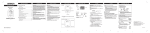
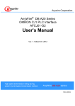
Anywire Corporation
Open Terminal series
MECHATROLINK Bit Distributed I/O Terminal
AB023-M1
User’s Manual
Version 1.0 June 23, 2005
Bit Control & Information Transmission
Sho-haisen system
Open Terminal series
ab023m1uma
Precautions
Precautions for this manual
1.
2.
3.
4.
5.
Please deliver this User’s Manual to the end user.
Please read this User’s Manual carefully and understand the details of the product well
before you start using it.
This manual explains the details of the functions including in the product, but does not
guarantee the compatibility to user’s own purpose.
It is prohibited to reprint or reproduce a part of this manual or all without permission.
The contents of this manual may be changed without notice.
The indications of warnings and cautions for safe and correct use
Indicates a potentially hazardous situation, which, if not avoided, could result in
death or serious injury.
Indicates a potentially hazardous situation, which, if not avoided, could cause
personal injury or damage.
The precautions for using the system under safety condition
◆ AnyWire System is not intended to have control functions for securing safety.
◆ In the following cases, special consideration is necessary for the usage
sufficient for ratings and functions, and necessary for safeguard such as
fail-safe function. And also, please contact our company.
(1) ications requiring higher safety
1- Applications expected to have a great influence on life or property
1- Medical equipment, or safety devices
(2) ications requiring higher reliability of system
1- Applications for vehicle control or burning control system
◆Be sure to turn the power off before installation or replacement.
◆ Be sure to use AnyWire System within the specifications and conditions
prescribed in this manual.
i
◆ Be sure not to turn on the 24V power before completing wiring and
connecting in AnyWire System.
◆ Use a regulated power supply of 24V DC. Non-regulated power supply may
cause a trouble to the system.
◆ Keep transmission cables and I/O cables away from high-voltage and power
cables, though the AnyWire System has high noise margin.
◆ Be careful not to allow metal bits into the unit, the connectors or the terminal
blocks, especially when wiring.
◆ Mis-wiring may cause failure. Consider the length and installation of cable
wiring to keep connectors and cables from disconnecting or excessive
distortion.
◆ Never solder the stranded wire to be connected with the terminal block,
otherwise causing a defective contact.
◆ In case of long cable length of power line along the transmission lines, large
voltage drops will occur and may cause voltage shortage for the distant
Slave Units. In that circumstance, connect the local power supply units so
that the prescribed voltage is secured at each local Slave Unit.
◆ Be careful of the following items about installation environment.
· No exposing directly to the sunlight and ambient temperature is 0 to +55 ˚C.
· Operating relative humidity is 10 to 90 % and no dew condensation by
sudden temperature change
· No corrosive or inflammable gases
· No direct vibration or impact
◆ Fasten terminal screws securely to avoid malfunction.
◆ In case of storage of the product, keep away from high temperature and
high humidity. (Storage temperature is –20 to 75˚C.)
◆ When the emergency stop circuit or the interlock circuit for safety are
arranged, provide these circuits outside the AnyWire System.
ii
INDEX
1
OUTLINE ................................................................
................................................................................................
................................................................................................
...........................................................................................
........................................................... 1-1
2
SPECIFICATION ................................................................
................................................................................................
................................................................................................
..........................................................................
..........................................2
.......... 2-1
3
2.1.
GENERAL SPECIFICATIONS............................................................................................................................................ 2-1
2.2.
CAPABILITY SPECIFICATIONS ....................................................................................................................................... 2-1
2.3.
DIMENSION ........................................................................................................................................................................... 2-3
2.4.
NAME OF EACH PART ...................................................................................................................................................... 2-4
2.5.
DETACHING TO DIN RAIL ............................................................................................................................................... 2-5
SWITCH SETTING ................................................................
................................................................................................
................................................................................................
......................................................................
......................................3
...... 3-1
3.1.
4
3.1.1.
Operating mode setting (MODE) .....................................................................................................................................................3-1
3.1.2.
The station number setting (Station №)......................................................................................................................................3-1
REGISTER ALLOCATION................................
................................................................
................................................................................................
.......................................................................................
.......................................................4
....................... 4-1
4.1.
17byte mode .............................................................................................................................................................................................4-1
4.1.2.
32byte mode .............................................................................................................................................................................................4-2
4.1.3.
Alarm ............................................................................................................................................................................................................4-3
4.1.4.
Status ..........................................................................................................................................................................................................4-3
4.1.5.
Slave response alarm reset output ................................................................................................................................................4-3
7
8
iii
MODULE DEFINITION ......................................................................................................................................................... 5-1
5.1.1.
Parameter setting...................................................................................................................................................................................5-2
5.1.2.
Link allocation ..........................................................................................................................................................................................5-3
5.1.3.
I/O Map.......................................................................................................................................................................................................5-5
5.1.4.
Status ..........................................................................................................................................................................................................5-6
5.1.5.
MECHATROLINK Saving Defined Data ........................................................................................................................................5-6
5.1.6.
I/O register allocation example........................................................................................................................................................5-7
MONITORING FUNCTION................................
................................................................
................................................................................................
.......................................................................................
.......................................................6
....................... 6-1
6.1.
AUTOMATIC ADDRESS RECOGNITION........................................................................................................................ 6-1
6.2.
MONITORING OPERATION ............................................................................................................................................... 6-1
LED INDICATION ................................................................
................................................................................................
................................................................................................
........................................................................
........................................7
........ 7-1
7.1.
MECHATROLINK SIDE ................................................................................................................................................ 7-1
7.2.
SHO-HAISEN BUS SIDE .................................................................................................................................................... 7-1
CONNECTIONS ................................................................
................................................................................................
................................................................................................
...........................................................................
...........................................8
........... 8-3
8.1.
9
DATA FORMAT .................................................................................................................................................................... 4-4
SETTING FROM THE PROGRAMMING TOOL ................................................................
.............................................................................
.............................................5
............. 5-1
5.1.
6
MP2000 SERIES................................................................................................................................................................. 4-1
4.1.1.
4.2.
5
MECHATROLINK SIDE ................................................................................................................................................ 3-1
TERMINATOR ....................................................................................................................................................................... 8-4
TIME REQUIRED FOR TRANSMISSION................................
................................................................
............................................................................................
............................................................ 9-1
9.1.
INPUT .........................................................................................................................................................................................9-1
9.2.
OUTPUT ....................................................................................................................................................................................9-1
10
TROUBLE SHOOTING ................................................................
................................................................................................
......................................................................................
...................................................... 10-
10-1
10.1.
MECHATROLINK SIDE .........................................................................................................................................10-1
10.2.
SHO-HAISEN BUS SIDE ..................................................................................................................................................10-1
11
CHANGE HISTORY ................................................................
................................................................................................
............................................................................................
............................................................ 11-
11-1
iv
1 Outline
Bit decentralization I/O terminal is the best for MECHATROLINK when I/O under the Link controlling more
distribution in detail.
The I/O signal and the power supply can be sent to the terminal (D-I/O terminal) in two wires transmission lines.
Even if the divergence of wiring is done, the disconnection detection is possible.
The maximum input 256 points and the output 256 points a unit of AB023-M1 can be capable for input and
output operation.
(The number of I/O points per one system of AB023-M1 <Bit distributed I/O terminal/bus copular>
NOTE) Note) MECHATROLINK is the registered trademark of YASKAWA Electric Corporation in Japan.
AB023-M1
Slave input unit
・・
Sho-haisen Bus
Output slave unit
Slave input unit
Output slave unit
・・
1-1
2
Specification
2.1.
General Specifications
Ambient operating
0℃ ... +55℃
Temperature
Storage
- 20℃ ... +75℃
Temperature
Storage Humidity
Ambient Atmosphere
2.2.
10% ... 90%RH (No condensation)
No corrosive or flammable gas
Capability Specifications
System Specifications on Sho-haisen Bus side
Transmission Clock
28.7 KHz
Transmission Mode
Total frame cyclic method with DC power supply on common wire
Connection Form
Bus Form (A Multi-drop Method, a T-branch Method, a Tree Branch Method)
Transmission Protocol
Special protocol(AnyWire Bus-e protocol)
Number of Connection
432 points (IN: 216 points OUT: 216 points) or 192 points (IN: 96 points OUT:
I/O points
Number of the
96 points)
Up to 128 units (Changed by consumption current of each unit)
connection points
Transmission Cycle
Time
5.5ms/IO 192 points 10.2ms/IO432 points
Note) The transmission cycle time reaches the value between 1 to 2 cycle times.
(1 cycle time value)
Connection Cable
Maximum Transmission
Distance
Supply Maximum
General-purpose 2-wire cable (0.75 mm² ... 2.0 mm²)
During operation of rated 24 V: 50m(1.25 mm² electric cable)
Condition: 2 A load current, a relay drive ability distance
2A
Current of transmission
Power supply voltage
Range of voltage during
DC26.4V (24-VDC rated supply)
Power source supply is unnecessary. (supplied from the transmission line)
use slaves
Supply voltage of slave
load
2-1
Power source supply is unnecessary. (supplied from the transmission line)
System Specification on MECHATROLINK side (when connected to the MP2000 series machine
controller made by YASUKAWA Electric Corp.)
MECHATROLINK-Ⅰ
Version
MECHATROLINK-Ⅱ
Transmission Method
Bus
Bus
Maximum Transmission
50 m
50 m
0.5 m
0.5 m
4Mbps
10Mbps
Communication Cycle
2ms
1ms, 1.5 ms or 2 ms
Number of Maximum
14 stations
21 stations
Cyclic Method
Cyclic Method
Distance
Minimum Station
Distance
Transmission Speed
Connection stations
Transmission Control
Method
- This unit can be used with the products of the versions shown below or later.
Programming device software MPE720: V5.32
MP2000 Series machine controller CPU: V2.42
MECHATROLINK interface module SVB-01: V1.15
- This unit uses intelligent I/O.
- MECHATROLINK-I (17-byte mode), MECHATROLINK-II (17-byte mode), and MECHATROLINK-II
(32-byte mode) are supported.
- The unit supports asynchronous communication, but not synchronous communication.
- The 0.5-ms communication cycle is not supported.
- It takes about 30 ms before the data input from this unit or the data output from the slave unit is updated
after the status of the MP2000 Series CPU is changed from STOP to RUN. Data before the update is
treated as "off" data.
2-2
2.3.
Dimension
(*印寸法はカバー開放時の寸法)
* is a size when opened the cover.
****印寸法はDINレール搭載時の寸法
is a size when installed the CIN rail.
(** is a size when(**はDINレール搭載時の寸法)
installed the CIN rail.)
2-3
2.4.
Name of Each Part
MECHATROLINK接続コネクタ
MODE設定
スイッチ
Station No.
設定スイッチ
モニタ接続
ポート
SETスイッチ
表示LED
Bitty接続端子
Japanese
English
MECHATROLINK接続コネクタ
MECHATROLINK Connection Connector
MODE設定スイッチ
MODE setting switch
モニタ接続ポート
Monitor Connection Port
Station No. 設定スイッチ
Station No. setting switch
SETスイッチ
SET Switch
表示LED
Indication LED
2-4
2.5.
Detaching to DIN Rail
Please use and install this unit on the DIN.
1. How to install this unit on DIN rail
[1] A fixed pick upper in the bottom is put on the DIN rail.
[2] This device is pressed against the DIN rail and sets it.
Install
取り付け
2. How to detach this unit from DIN rail
The hook comes off from the rail when a minus driver is defeated
to the difference all-in in the hook and the driver is defeated to
this device side.
The main body fixation pick side is detached, and under such a
condition, please lift and detach the main body hook side to the
starting point.
[2]
②
[2]
②
Detach
取り外し
[1]①
2-5
[1]
①
3 Switch Setting
3.1.
MECHATROLINK side
3.1.1.
Operating mode setting (MODE)
Indication
Name
Status
Function
Setting at shipping
Communication
ON
MECHATROLINK-II (10Mbps)
ON
speed setting
OFF
MECHATROLINK-I (4Mbps)
I/O byte setting
ON
32byte mode
OFF
17byte mode
MECHATROLINK
ON
7xh
Upper address
OFF
6xh
-
Use at OFF
Name
1
2
3
OFF
OFF
setting
4
System reserved
OFF
432 points at 32byte-mode transmission (IN: 216 points, OUT: 216 points)
192 points at 17byte-mode transmission (IN: 96 points, OUT: 96 points)
For MECHATROLINK-I, a baud rate of 4 Mbps and the 17-byte mode are used.
3.1.2.
The station number setting (Station №)
Set the station number of MECHATROLINK-I.
When connecting more than one unit, take care to avoid station number overlap.
Station numbers from 61H to 7EH can be set using the Station number switch in combination with the MODE
switch 3. For the MP2000 Series machine controller made by YASUKAWA Electric Corp., however, the
maximum station number must be as shown in the table below.
Communication
Transmission
Communication
Number of slave
Maximum
Method
Speed
Cycle
stations
Station No.
MECHATROLINK-I
4Mbps
2 ms
14 stations
6EH
MECHATROLINK-II
10Mbps
1 ms
15 stations
6FH
1 ms
9 stations
69H
1.5ms
15 stations
6FH
2 ms
21 stations
75H
(17byte mode)
MECHATROLINK-II
(32byte mode)
10Mbps
3-1
The station number setting list
ST# (station No.)
Switch Setting
MODE Switch “3”
Station No. Switch
01 (61H)
OFF
1
02 (62H)
OFF
2
03 (63H)
OFF
3
04 (64H)
OFF
4
05 (65H)
OFF
5
06 (66H)
OFF
6
07 (67H)
OFF
7
08 (68H)
OFF
8
09 (69H)
OFF
9
10 (6AH)
OFF
A
11 (6BH)
OFF
B
12(6CH)
OFF
C
13 (6DH)
OFF
D
14 (6EH)
OFF
E
15 (6FH)
OFF
F
16 (70H)
ON
0
17 (71H)
ON
1
18 (72H)
ON
2
19 (73H)
ON
3
20 (74H)
ON
4
21 (75H)
ON
5
Values 01 to 21 are the station numbers that are displayed in the Link Allocation window and other windows of
the programming device software MPE720.
- The 0.5-ms communication cycle is not supported.
- Communication cannot be performed when station number 60H is set.
- Before setting the DIP switches, be sure to turn off the power.
- Set the DIP switches according to the transmission specifications in use.
- If the transmission specifications of this unit do not match those of the connected
slave unit, data may not be transmitted normally, possibly causing a malfunction.
3-2
4
4.1.
Register allocation
MP2000 series
This section describes the register allocation pattern to be used when the MP2000 series machine controller
made by YASUKAWA Electric Corporation is used as the master unit.
4.1.1.
17byte mode
In the 17-byte mode, 96 points of input and 96 points of output can be transmitted.
Input
Input Register
15
14
13
12
11
10
9
8
7
6
5
4
3
IWxxxx
Alarm
System Usage
IWxxxx+1
Status High
Status Low
2
1
0
IWxxxx+2
15
14
13
12
11
10
9
8
7
6
5
4
3
2
1
0
IWxxxx+3
31
30
29
28
27
26
25
24
23
22
21
20
19
18
17
16
IWxxxx+4
47
46
45
44
43
42
41
40
39
38
37
36
35
34
33
32
IWxxxx+5
63
62
61
60
59
58
57
56
55
54
53
52
51
50
49
48
IWxxxx+6
79
78
77
76
75
74
73
72
71
70
69
68
67
66
65
64
IWxxxx+7
95
94
93
92
91
90
89
88
87
86
85
84
83
82
81
80
15
14
13
12
11
10
9
8
7
6
5
4
3
2
1
0
Output
Output
Register
OWxxxx
For option
System reserved
OWxxxx+1
For option
*1
OWxxxx+2
15
14
13
12
11
10
9
8
7
6
5
4
3
2
1
0
OWxxxx+3
31
30
29
28
27
26
25
24
23
22
21
20
19
18
17
16
OWxxxx+4
47
46
45
44
43
42
41
40
39
38
37
36
35
34
33
32
OWxxxx+5
63
62
61
60
59
58
57
56
55
54
53
52
51
50
49
48
OWxxxx+6
79
78
77
76
75
74
73
72
71
70
69
68
67
66
65
64
OWxxxx+7
95
94
93
92
91
90
89
88
87
86
85
84
83
82
81
80
* Slave response alarm reset output
4-1
4.1.2.
32byte mode
In the 32-byte mode, 216 points of input and 216 points of output can be transmitted.
Input
Input Register
15
14
13
12
IWxxxx
11
10
9
8
7
6
5
Alarm
IWxxxx+1
4
3
2
1
0
System Used
Status High
Status Low
IWxxxx+2
15
14
13
12
11
10
9
8
7
6
5
4
3
2
1
0
IWxxxx+3
31
30
29
28
27
26
25
24
23
22
21
20
19
18
17
16
IWxxxx+4
47
46
45
44
43
42
41
40
39
38
37
36
35
34
33
32
IWxxxx+5
63
62
61
60
59
58
57
56
55
54
53
52
51
50
49
48
IWxxxx+6
79
78
77
76
75
74
73
72
71
70
69
68
67
66
65
64
IWxxxx+7
95
94
93
92
91
90
89
88
87
86
85
84
83
82
81
80
IWxxxx+8
111 110 109 108 107 106 105 104 103 102 101 100
99
98
97
96
IWxxxx+9
127 126 125 124 123 122 121 120 119 118 117 116 115 114 113 112
IWxxxx+A
143 142 141 140 139 138 137 136 135 134 133 132 131 130 129 128
IWxxxx+B
159 158 157 156 155 154 153 152 151 150 149 148 147 146 145 144
IWxxxx+C
175 174 173 172 171 170 169 168 167 166 165 164 163 162 161 160
IWxxxx+D
191 190 189 188 187 186 185 184 183 182 181 180 179 178 177 176
IWxxxx+E
207 206 205 204 203 202 201 200 199 198 197 196 195 194 193 192
IWxxxx+F
Not Used
215 214 213 212 211 210 209 208
Output
Output
15
14
13
12
11
10
9
8
7
6
5
4
3
2
1
0
Register
OWxxxx
For Option
System reserved
OWxxxx+1
For option
*1
OWxxxx+2
15
14
13
12
11
10
9
8
7
6
5
4
3
2
1
0
OWxxxx+3
31
30
29
28
27
26
25
24
23
22
21
20
19
18
17
16
OWxxxx+4
47
46
45
44
43
42
41
40
39
38
37
36
35
34
33
32
OWxxxx+5
63
62
61
60
59
58
57
56
55
54
53
52
51
50
49
48
OWxxxx+6
79
78
77
76
75
74
73
72
71
70
69
68
67
66
65
64
OWxxxx+7
95
94
93
92
91
90
89
88
87
86
85
84
83
82
81
80
OWxxxx+8
111 110 109 108 107 106 105 104 103 102 101 100
99
98
97
96
OWxxxx+9
127 126 125 124 123 122 121 120 119 118 117 116 115 114 113 112
OWxxxx+A
143 142 141 140 139 138 137 136 135 134 133 132 131 130 129 128
OWxxxx+B
159 158 157 156 155 154 153 152 151 150 149 148 147 146 145 144
OWxxxx+C
175 174 173 172 171 170 169 168 167 166 165 164 163 162 161 160
OWxxxx+D
191 190 189 188 187 186 185 184 183 182 181 180 179 178 177 176
OWxxxx+E
207 206 205 204 203 202 201 200 199 198 197 196 195 194 193 192
OWxxxx+F
Not Used
215 214 213 212 211 210 209 208
*1 Slave response alarm reset output
4-2
4.1.3. Alarm
The high-order bytes of IWxxxx contain alarm information.
The code is represented in hexadecimal notation. Code 00 indicates the normal status. Codes 01 to 7F are for
MECHATROLINK, and codes 80 and larger are for Sho-haisen bus.
Alarm code (Hex)
Factors
00
Normal
01
An unsupported command was received.
A command inconsistent with the communication phase was received.
02
The command execution condition is not met.
4.1.4.
03
The data in the command is invalid.
80
Short circuit between Sho-haisen bus DP and DN
81
Slave response alarm (transmission line cut, slave failure, etc.)
Status
IWxxxx+1 contain status information.
This unit does not use a warning bit.
Bit
Name
B0
Alarm bit
B1
B2
B3 ... 15
Factors
0
No alarm
1
Alarm
Warning
0
No warning
bit
1
Warning
Command
0
Not ready to receive a command
ready bit
1
Ready to receive a command
System
Always “0”
reserved
4.1.5.
Slave response alarm reset output
Bit 0 of OWxxxx+1 is used for slave response alarm reset output.
If the cause of the response alarm has been eliminated, changing the value of this bit from 0 to 1 resets the alarm
code to 00 and turns off the ALM LED.
The slave response alarm reset output may fail to reset alarm information when the alarm
is remedied after the slave unit is detached and attached with the power on or there is a
temporary line disconnection due to poor contact or some other cause. In this case, turn
the power off and then back on.
4-3
4.2.
Data Format
This section describes the data format of MECHATOLINK.
Refer to this section when used in other controller.
Output data is started from 5 byte at command. Alarm is from 2 byte, status is from 3 or 4 byte and input data is
from 5 byte at response.
17byte mode
Byte
Command
Response
1
System used
System used
2
For option
Alarm
3
For option
4
*1
Status Low
For option
Status High
5
7
6
5
4
3
2
1
0
7
6
5
4
3
2
1
0
6
15
14
13
12
11
10
9
8
15
14
13
12
11
10
9
8
7
O
23
22
21
20
19
18
17
16
I
23
22
21
20
19
18
17
16
8
U
31
30
29
28
27
26
25
24
N
31
30
29
28
27
26
25
24
9
T
32
P
39
38
37
36
35
34
33
32
10
P
40
U
47
46
45
44
43
42
41
40
11
U
55
54
53
52
51
50
49
48
T
55
54
53
52
51
50
49
48
12
T
63
62
61
60
59
58
57
56
63
62
61
60
59
58
57
56
64
D
71
70
69
68
67
66
65
64
72
A
79
78
77
76
75
74
73
72
87
86
85
84
83
82
81
80
95
94
93
92
91
90
89
88
13
14
15
16
39
47
71
D
A
T
79
87
95
38
46
70
78
86
94
37
45
69
77
85
93
36
44
68
76
84
92
35
43
67
75
83
91
34
42
66
74
82
90
33
41
65
73
81
89
80
88
T
A
A
*1 Slave response alarm reset output
4-4
32byte mode
Byte
Command
Response
1
System used
System used
2
For option
3
Alarm
For option
4
*1
Status Low
For option
Status High
5
7
6
5
4
3
2
1
0
7
6
5
4
3
2
1
0
6
15
14
13
12
11
10
9
8
15
14
13
12
11
10
9
8
23
22
21
20
19
18
17
16
7
23
22
21
20
19
18
17
16
24
I
31
30
29
28
27
26
25
24
32
N
39
38
37
36
35
34
33
32
8
O
9
U
10
T
47
46
45
44
43
42
41
40
P
47
46
45
44
43
42
41
40
11
P
55
54
53
52
51
50
49
48
U
55
54
53
52
51
50
49
48
12
U
63
62
61
60
59
58
57
56
T
63
62
61
60
59
58
57
56
13
T
71
70
69
68
67
66
65
64
71
70
69
68
67
66
65
64
79
78
77
76
75
74
73
72
87
86
85
84
83
82
81
80
95
94
93
92
91
90
89
88
103
102
101
100
99
98
97
96
14
15
16
17
31
39
79
D
A
T
87
95
30
38
78
86
94
29
37
77
85
93
28
36
76
84
92
27
35
75
83
91
26
34
74
82
90
25
33
73
81
89
72
80
88
D
A
T
A
103
102
101
100
99
98
97
96
111
110
109
108
107
106
105
104
111
110
109
108
107
106
105
104
19
119
118
117
116
115
114
113
112
119
118
117
116
115
114
113
112
20
127
126
125
124
123
122
121
120
127
126
125
124
123
122
121
120
135
134
133
132
131
130
129
128
135
134
133
132
131
130
129
128
143
142
141
140
139
138
137
136
143
142
141
140
139
138
137
136
151
150
149
148
147
146
145
144
151
150
149
148
147
146
145
144
159
158
157
156
155
154
153
152
159
158
157
156
155
154
153
152
167
166
165
164
163
162
161
160
175
174
173
172
171
170
169
168
18
21
22
23
24
A
O
U
T
P
I
N
P
U
25
U
167
166
165
164
163
162
161
160
26
T
175
174
173
172
171
170
169
168
27
183
182
181
180
179
178
177
176
D
183
182
181
180
179
178
177
176
28
D
191
190
189
188
187
186
185
184
A
191
190
189
188
187
186
185
184
29
A
199
198
197
196
195
194
193
192
T
199
198
197
196
195
194
193
192
30
T
207
206
205
204
203
202
201
200
A
207
206
205
204
203
202
201
200
31
A
215
214
213
212
211
210
209
208
215
214
213
212
211
210
209
208
T
*1 Slave response alarm reset output
4-5
5
Setting from the Programming Tool
5.1.
Module definition
This section describes how to define AB023-M1 from the Engineering window of the programming device
software MPE720, using an example of MP2300. (Use MPE720 of Version 5.32 or later.)
(1) Module configuration
When you open "Module Configuration Definition" in "Definition Folder" in the "File Manager" window of
MPE720, the following window appears.
5-1
(2) MECHATROLINK Definition window
When you double-click "MECHATROLINK" for the module "SVB" in the Module Configuration window, the
following MECHATROLINK Definition window appears.
5.1.1.
Parameter setting
Communication method
From the combo box menu, select MECHATROLINK-I, MECHATROLINK-II (17-byte mode), or
MECHATROLINK-II (32-byte mode).
Communication Cycle
The communication cycle is determined by the communication method, as shown in the table below.
Communication method
Communication Cycle
MECHATROLINK-I
2 ms, fixed
MECHATROLINK-II (17byte mode)
1 ms, fixed
MECHATROLINK-II (32byte mode)
Select 1 ms, 1.5 ms, or 2 ms.
SigmaWin
Available only for MECHATROLINK-II. Select Do not use or Use.
Number of retry stations (message)
Available only for MECHATROLINK-II.
5-2
5.1.2. Link allocation
When you double-click the "Link Allocation" tab window in the MECHATROLINK Definition window, the message
"Saving data, OK?" appears. To save the data, click "Yes" (when any data in the Parameter Setting tab window has
been changed).
The following Link Allocation window appears.
Setting Items
Contents
ST#
ST#
The station numbers are shown.
The ST# column is set according to the station numbers of AB023-M1. "01" is set for
station number 61H, or "16" is set for 70H.
The maximum station number to be displayed is determined by the communication
method and communication cycle.
TYPE
Select AB023-M1 from the combo box menu.
This indicates the disable status of the input register. Checking the box disables the
corresponding register.
Set the start input register number and the register count (SIZE) (hexadecimal word
address).
Make sure that there is no register range overlap among stations.
The range of specifiable register numbers is determined by the range defined by the
I/O start and end register numbers specified in the Module Configuration window.
When you set the input register, the register size is automatically set to either 8 if the
17-byte mode is set as the communication method or 16 (decimal) if the 32-byte
mode is set as the communication method.
This indicates the disable status of the output register. Checking the box disables the
corresponding register.
Set the start output register number and the register count (SIZE) (hexadecimal word
address).
Make sure that there is no register range overlap among stations.
The range of specifiable register numbers is determined by the range defined by the
I/O start and end register numbers specified in the Module Configuration window.
When you set the output register, the register size is automatically set to either 8 if
the 17-byte mode is set as the communication method or 16 (decimal) if the 32-byte
mode is set as the communication method.
D
INPUT,
INPUT, SIZE
D
OUTPUT,
OUTPUT, SIZE
5-3
SCAN
Station Name
In SCAN (data exchange cycle), specify the timing for the exchange of I/O data
between the controller CPU and AB023-M1.
Select either High or Low.
High: Exchange I/O data by the CPU's high-speed scan.
Low: Exchange I/O data by the CPU's low-speed scan.
Enter a comment on each station using up to 32 one-byte characters (or 16 two-byte
characters).
The following window shows a setting example where MECHATROLINK-II (32-byte mode) and station number 61H
are set.
5-4
5.1.3. I/O Map
When you double-click the "I/O Map" tab window in the MECHATROLINK Definition window, the message "Saving
data, OK?" appears. To save the data, click "Yes" (when any data in the Link Allocation tab window has been
changed).
The following I/O Map window appears.
This window allows you to check and change the scan type (High or Low) you have allocated to each station in the
"Link Allocation" tab window, on a word-by-word basis using abbreviations (HI, HO, LI, and LO).
Operation button
Meaning
HI
Allocated to high scan input.
HO
Allocated to high scan output.
LI
LO
DEL
Allocated to low scan input.
Allocated to low scan output.
Delete the allocation.
In the I/O Map window, you can change the scan type (from LI to HI or vice versa), but not the I/O type (from LO
to LI or vice versa).
5-5
5.1.4. Status
Click the "Status" tab window in the MECHATROLINK Definition window.
The data currently transmitted by MECHATROLINK is displayed.
This tab window is for status display only and cannot be used to change the set values.
The items in this window have the same meanings as those in the "I/O Map" tab window, except for the
additional "STS" column.
STS
In online mode, the MECHATROLINK transmission status is displayed in hexadecimal notation.
The meaning of each bit is described below. Note that the field is blank when in offline mode.
F
E
D
C
B
A
9
8
7
6
5
4
3
2
1
0
System reserved
Spare
Transmission error (High-speed scan)
Transmission error (Low-speed scan)
Spare
Normal transmission
5.1.5. MECHATROLINK Saving Defined Data
The procedure for saving the defined MECHATROLINK data is as follows.
1. Click "File (F)" - "Save (S)".
2. To save the defined data, click "Yes (Y)" in the message box.
Choosing "Save & Save to Flash" saves the defined data to the CPU's flash memory as well.
5-6
5.1.6.
I/O register allocation example
This is an example where MECHATROLINK-II (32-byte mode) and station number 61H are set.
MP2000 series
MECHATROLINK
Open Terminal series・I/O terminal (Bitty)
1 2 34
Address 4
Address 8
Address 0
Address 0
STAT ION .No.
MODE
MechatroLink
MONITOR
Input 8-point slave
SET
Output 4-point slave
Input 8-point slave
Output 4-point slave
Op en Terminal
AB023-M1
RDY
TXD
L IN K
R XD
24V
24V
LG
ALM
SET
DP
0V
Sho-haisen Bus
DP
DN
DN
Address 8
Address 16
Address 16
Address 32
AB023-M1
Input 16-point slave
Input unit
Address
Output 8-point slave
Register and bits
Output unit
Input 16-point slave
Address
used
Input 8-point
0
0 ... 7 of IW0012
unit
Input 8-point
unit
5-7
Output 16-point slave
Register and bits
used
Output 4-point
0
0 ... 3 of OW0022
4
4 ... 7 of OW0022
unit
8
8 ... F of IW0012
Output 4-point
unit
Input 16-point
16
0 ... F of IW0013
32
0 ... F of IW0014
slave
Input 16-point
unit
Output 8-point
8
8 ... F of OW0022
16
0 ... F of OW0023
unit
Output 16-point
unit
** Registers and bits other than the ones shown above are not used.
5-8
6 Monitoring Function
Overview
Each I/O terminal of Sho-haisen Bus series has unique address, and returns back the reply when the address
sent from this device is correspondent to its own address number. The device, by checking the response
signals, detects wire disconnection and confirms that the I/O terminal is in place.
This device, with its address auto-recognizing operation (description given later), memorizes the ID
(addresses) of the connected I/O terminal into EEPROM. This information will remain in storage even if power
is turned off.
Then the device sends out the registered ID (addresses) in sequence through the transmission line, and if
there is no response to these, it will recognize this as wire disconnection, which will be displayed by the "ALM"
LED.
6.1.
Automatic Address Recognition
Storing the IDs (addresses) of the connected I/O terminals in this unit's E2PROM is called "automatic address
recognition".
Procedure
1. Check that all the IDs (addresses) are in the normal operation status (the "LINK" LED is blinking).
2. Hold down the "SET" switch until the "SET" LED (orange) comes on.
3. When the "SET LED" rapidly blinks and then goes off, the storage of the address is complete.
During automatic address recognition, input/output operation may not work. Be sure to
carry on automatic address recognition, when the program of PLC stops or in the
condition that there is no interference in the movement of the machine.
On abnormal status in the Sho-haisen Bus such as short-circuit, or for five seconds
after turning on the power or resetting, automatic address recognition can not be
operated.
6.2.
Monitoring Operation
The unit sends the registered addresses sequentially. If no response is returned to any of these addresses,
the unit regards the corresponding I/O terminal as being disconnected and turns on the "ALM" LED.
This alarm information is retained until the power is turned off or the information is reset by the slave response
alarm reset output.
When the ALM LED is on before automatic address recognition is performed or because of line disconnection,
data is transmitted for the normally connected I/O terminals.
6-1
7 LED Indication
LED indication part
Indication part
表示部
24V
7.1.
T XD
RDY
ALM
R XD
LIN K
SET
24V
MECHATROLINK side
LED
Function
Color
Contents of Light up indication
Send
Green
Lights up while MECHATROLINK is sending
Green
Lights up while MECHATROLINK is received.
Name
TXD
indication
RXD
Receive
indication
TXD LED
RXD LED
Goes out
Lights up
(Green)
Causes
The settings of the MECHATROLINK master unit do not match those of
AB023-M1.
1. Communication speed
2. Number of Input/output bytes
Goes out
Goes out
3. Station Number
Disconnection of the communication line
The cable is not plugged properly.
Unit failure
7.2.
Sho-haisen Bus side
●Indication of the status of Shohai-sen Bus
LED
Function
Color
Ready
Green
Meaning
Name
RDY
Lights up
This unit is in operation.
Goes out
The transmission line DP or DN is disconnected, or the
Flashing
Data is being transmitted normally.
Goes out
This unit is faulty.
Lights up
The transmission line DP or DN is disconnected or
slave unit does not respond.
LINK
Transmission
Green
Indication
ALM
Alarm
Red
Indication
No response from slaves.
Flashing
SET
Address
automatic
7-1
Orange
Short circuit between DP and DN
Goes out
Data is being transmitted normally.
Lights up
Automatic address recognition is in progress.
Goes out
Data is being transmitted normally.
recognition
Flashing
The recognized address is being written o EEPROM.
indication
7-2
8 Connections
MECHATROLINK side
For information about how to connect the MECHATROLINK part, refer to the user's
manual of the machine controller made by YASUKAWA Electric Corporation or other
relevant documents.
There are two connectors. The right one and the left one are both the same.
No.
Signal
Content
12 3 4
Name
1
NC
Not used
2
/DATA
Signal - side
3
DATA
Signal + side
4
SH
Communication cable shield
Shield
Frame ground
STATIO N.No.
MODE
MECHATROLINK
MONITOR
Shell
SET
Open Terminal
AB023-M1
As the MECHATROLINK cable, use JEPMC-W6002-**.
Plug USB terminator JEPMC-W6022 into each unused port.
TXD
RDY
ALM
R XD
LIN K
SET
24V
24V
LG
DP
0V
DP
DN
DN
Sho-haisen Bus side
An eight-pole M3 screw terminal block is on this side.
Connectable wire: AWG22 - AWG14
Tightening torque: 0.8N-m
Connect a 24 VDC stabilized power supply.
24 V
Its capacity of electric current must be +2 A or more, which is
0V
necessary for the load and slave unit.
DP
DN
LG
Transmission line (+ side)
Transmission line (- side)
Connected to the neutral point of the noise filter.
Ground it in the event of a malfunction caused by 24-V power noise.
In that case, the grounding work of Class D rating must be conducted
individually.
Connect a slave unit of the Bitty Series. DB series slave unit cannot be connected.
Connect the DP and DN terminals to their counterparts on the slave unit, respectively. (Refer to the user's
manual of each unit in use.)
8-3
* Do not use plural transmission Line (D, G) with many cable lines together.
It has the possibility that the equipment operates faultily due to the cross talk when it is
transmitted together.
2
* Set the diameter of the transmission line at more than 0.75 mm , when transmission distance is
until
2
200 m. Set the diameter of the transmission line at more than 0.9 mm , when transmission
distance is more than 200 m.
* When transmission distance is until 200 m, the lower limit of the power supply voltage is more
than 21.6 V. When transmission distance is more than 200 m, the lower limit of the power supply
voltage is 24 V.
* Be careful of the voltage drop by the cable. Equipment operates faultily due to the voltage drop.
Supply a power supply in the terminal side when a voltage drop is big. (A local power supply)
* A line to connect to the connector terminal isn't to do solder. A line causes a looseness contact
defect.
8.1.
Terminator
Connect one AT0 terminator to the far end of Sho-haisen bus line.
Otherwise, the line may not be able to transmit data normally.
AB023-M1
Slave Terminal
Sho-haisen Bus
Slave Terminal
AT0
8-4
9 Time Required for Transmission
9.1.
Input
Since the input area data is not updated unless the same data is received twice consecutively on Sho-haisen
bus side of the unit (double checking), the transmission time must be at least 1-cycle time or up to 2-cycle
time. The unit may not be able to capture a signal shorter than the 2-cycle time depending on the timing. To
ensure a response is returned, therefore, a signal longer than the 2-cycle time must be input.
The minimum Cycle Time
Case of the
Minimum Cycle
Time
One cycle time
Renewal of input data
Change of input data
The maximum Cycle Time
Case of the
Maximum Cycle
Time
Two Cycle Times
Change of input data
9.2.
Renewal of input data
Output
Since double collation performed by the slave unit side, the transmission time of a minimum of
one cycle time and a maximum of two cycles time is needed like the case of an input.
Term
Cycle time: Repetition transmission time of the actual data transmitted.
Maximum transmission delay time: Processing time by the side of a gateway
+ Refresh time + Slave side Signal delay time
Response delay time becomes as it is shown in the following figure.
9-1
Input/output
devices
Input
Output
[1] Input apparatus response time
AnyWire
System
[9] Output apparatus response time
[8] Slave side signal delay time
[2] Slave side signal delay time
[3] Transmission cycle time
[7] Transmission cycle time
[4] Gateway side processing time
DeviceNet
System
[6] Gateway side processing time
The maximum transmission delay time
The maximum transmission delay time
[5] RTEX System
Processing time
9-2
10 Trouble Shooting
10.1. MECHATROLINK side
Content of Trouble
TXD LED Goes out
RXD LED Lights up
Causes
The settings of the MECHATROLINK master
unit do not match those of AB023-M1.
[1] Communication speed
[2] Number of I/O byte
[3] Station No.
The station number is set to 60H.
The AnyWireBus communication line is
TXD LED Goes out
RXD LED Goes out
Input data of
AB023-M1 can not
be installed.
Output data of
AB023-M1 can not
turn off or on.
disconnected.
Cable is not connected properly.
Unit failure
Not read from the correct address of the input
register.
There is station number overlap.
Terminator is not connected.
Not read from the correct address of the output
register.
There is station number overlap.
Terminator is not connected.
How to check
Check the switch settings of
AB023-M1.
Check settings of the
MECHATROLINK master unit using
MPE720.
Replace the cable.
Check the cable.
Replace the unit.
Check the sequence program.
Check the station number.
Connect a terminator.
Check the Sequence program
Check the station number.
Connect a terminator.
10.2. Sho-haisen Bus side
First, check the following:
1. Whether the RDY LED of AB023-M1 is on
2. Whether the LINK LED of every unit is blinking
3. Whether the supply voltage of AB023-M1 is within the range of 24 V to 27.6 V
4. Whether wires are connected correctly and firmly
5. Whether the addresses are correct and whether there is no address overlap
Checklist by symptom
Symptom
Check Item
AB023-M1 side
Check whether the sho-haisen bus lines DP and DN are connected correctly.
Check whether power is supplied to the AB023-M1 unit.
Data cannot be input or output.
Slave Unit side
Check whether the sho-haisen bus lines DP and DN are connected correctly.
Check whether the address of the slave unit is set correctly.
The ALM LED (red) turns on.
The ALM LED (red) is blinking.
Check whether the DP and DN lines are not disconnected.
Check whether the address of the slave unit has not been changed after
automatic address recognition.
Check whether short between DP and DN
10-
10-1
11 Change History
Version
First edition
1.0 edition
11-
11-1
Date
Content of Change
March 14, 2005 Release
June 23, 2005
Assignment of the serial number
Anywire Corporation
■Headquarters (West Japan Office)
8-1, Shimoinden, Inouchi, Nagaokakyo-shi, Kyoto
617-0813 JAPAN
TEL: 075-956-1611 FAX: 075-956-1613
■East Japan Office
47, Kandakonya-cho, Chiyoda-ku, Tokyo 101-0035
JAPAN
TEL: 03-5209-5711 FAX: 03-5209-5713
■Chubu Office
2-26-15-507, Noritake, Nakamura-ku, Nagoya-shi,
Aichi 453-0014 JAPAN
TEL: 052-452-8711 FAX: 052-452-8713
■Kyoto Factory
19-2, Umatate, Kamiueno-cho, Muko-shi, Kyoto
617-0006 JAPAN
TEL: 075-922-1911 FAX: 075-922-1913