1
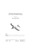
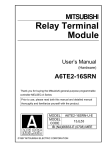
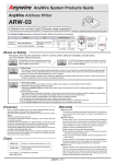
Anywire Corporation
AnyWire DB A20 Series
User’s Manual
RS-485 Modbus Gateway
AG20-485MD
Ver. 1.2
Integration of bit control and
information transmission
Wiring saving system
July 27, 2009
AnyWire DB A20 Series
PMA-0533D
Cautionary Instructions
Cautions about this manual
1. Please deliver this manual to end-users.
2. Read this manual thoroughly to understand the contents before operating this product.
3. This manual explains the details of functions equipped with this product, but does not
guarantee that the product will match a customer’s particular purpose.
4. Any reproduction or copying of this manual in whole or in part is expressly prohibited
without permission.
5. Information in this manual may be subject to change without notice in the future.
Warning displays
A “WARNING” indicates a potentially hazardous situation which, if not handled
!
WARNING
!
CAUTION
correctly, could result in personal serious injury or death.
A “CAUTION” indicates a potentially hazardous situation which, if not handled
correctly, could result in personal injury or property damage.
Safety precautions
!
WARNING
♦ The AnyWire system does not include any control functions to ensure safety.
♦ In any of the following cases, pay special attention to use with appropriate allowance for ratings
and functions and implement safety measures such as a fail-safe design and consult us for:
(1) Applications which require a high degree of safety
Applications predicted to have a great impact on human life or property
Medical equipment, safety equipment, etc.
(2) When used in systems which require a higher degree of reliability
Use in vehicle control, combustion control equipment, etc.
♦ Make sure to turn off the system power before installation or replacement work.
♦ Use the AnyWire system within the range of specifications and conditions defined in this manual.
i
!
CAUTION
♦ Do not turn on the 24V power supply before completing wiring and connection of the entire
AnyWire system.
♦ Use a stable, 24V DC power supply for AnyWire system equipment.
♦ Although the AnyWire system has high noise resistance, keep transmission cables and I/O
cables away from high-voltage and power cables.
♦ Be careful to prevent any waste metal from entering inside of units or connector parts, especially
during wiring.
♦ Mis-wiring may damage equipment. Pay attention to the cable length and layout in order to
prevent connectors and cables from being removed.
♦ Do not solder a stranded wire to be connected to the terminal block; otherwise a contact failure
may occur.
♦ If the wiring length of the power cable is long, voltage drops will occur and may cause shortages
of the power voltage of remote slave units. In that case, connect local power supply units to
ensure the specified voltage.
♦ Install the product by avoiding the following places:
· Where exposed to direct sunlight or the ambient operating temperature exceeds the range of
0°C to 55°C
· Where the operating relative humidity exceeds the range of 10% to 90% or condensation
occurs due to rapid temperature changes
· Where there is corrosive or inflammable gas
· Where subjected to direct vibration or shock
♦ Tighten terminal screws securely to avoid malfunctions, etc.
♦ When storing the product, avoid high temperatures and humidity. (Ambient storage temperature:
-20°C to 75°C)
♦ Incorporate the emergency stop circuit or interlock circuit for safety in an external circuit other
than the AnyWire system.
ii
CONTENTS
1
OVERVIEW ............................................................................................................................................................ 1-1
2
SPECIFICATIONS.............................................................................................................................................. 2-1
2.1.
GENERAL SPECIFICATIONS............................................................................................................................................. 2-1
2.2.
PERFORMANCE SPECIFICATIONS ................................................................................................................................. 2-1
2.3.
RS-485 MODBUS CONNECTION SPECIFICATIONS ................................................................................................. 2-2
2.4.
DIMENSIONAL OUTLINE DRAWING AND NAME OF EACH PART ............................................................................ 2-3
3
OPERATION MODE.......................................................................................................................................... 3-1
3.1.
OPERATION MODE SETTING (MODE SELECT).................................................................................................... 3-1
3.2.
INPUT AND OUTPUT POINT NUMBER SETTING (MODE SELECT)................................................................... 3-1
3.3.
RS-485 COMMUNICATION SETTINGS .......................................................................................................................... 3-2
3.4.
DEVICE NO. SETTING......................................................................................................................................................... 3-2
4
MEMORY MAP .................................................................................................................................................... 4-1
5
MONITORING FUNCTION............................................................................................................................. 5-1
5.1.
AUTOMATIC ADDRESS RECOGNITION ......................................................................................................................... 5-1
5.2.
MONITORING OPERATION ................................................................................................................................................ 5-1
6
ERROR STATUS ................................................................................................................................................ 6-1
6.1.
ERROR FLAG ........................................................................................................................................................................ 6-1
6.1.1.
6.2.
Reset method of error status...................................................................................................................................................6-2
ABNORMAL ADDRESS ....................................................................................................................................................... 6-2
7
LED DISPLAY ...................................................................................................................................................... 7-1
8
CONNECTION...................................................................................................................................................... 8-1
8.1.
ANYWIRE BUS/POWER SUPPLY CONNECTION ....................................................................................................... 8-1
8.2.
TERMINATOR ........................................................................................................................................................................ 8-2
8.3.
RS-485 CONNECTION ...................................................................................................................................................... 8-2
9
TRANSMISSION REQUIRED TIME.......................................................................................................... 9-1
9.1.
IN THE CASE OF INPUT ...................................................................................................................................................... 9-1
9.2.
IN THE CASE OF OUTPUT.................................................................................................................................................. 9-1
10
RS-485 MODBUS RTU PROTOCOL ................................................................................................10-1
10.1.
FUNCTION CODE ..........................................................................................................................................................10-1
10.2.
READ OUT COMMAND (FUNCTION CODE4).........................................................................................................10-1
10.3.
READ OUT COMMAND (FUNCTION CODE 16).....................................................................................................10-2
10.4.
CALCULATION OF CRC ............................................................................................................................................10-2
11
TROUBLESHOOTING ..............................................................................................................................11-1
12
WARRANTY ...................................................................................................................................................12-1
13
HISTORY OF CHANGES.........................................................................................................................13-1
iii
Overview
1 Overview
This machine can control input/output signals and collect data as a master interface of the
AnyWire DB A20 series by connection to a PLC equipped with Modbus protocol of RS-485.
The AnyWire system is a high speed, highly reliable wiring saving system with its own
transmission method.
Note) AnyWire is a registered trademark of AnyWire Corporation.
The AnyWire DB A20 series is a transmission system with a full-duplex transmission function.
The transmission distance 50 m / 100 m / 1 km / 3 km, and number of transmission points can
be selected with the switch.
Disconnection can be detected even for branch wires.
This unit allows to input/output the maximum input 512 points and output 512 points.
Modbus base unit
Modbus RTU
AG20-485MD
Modbus-AnyWire
Up to 15 units
AG20-485MD
GW
Modbus-AnyWire
AnyWire
AnyWire
Terminal
Terminal
AnyWire
AnyWire
Terminal
Terminal
GW
AnyWire Terminal 128 units Max.
1-1
Specifications
2 Specifications
2.1. General specifications
Operating power
voltage
Transmission line: 24V DC +15 to -10% (21.6 to 27.6V DC)
Operating ambient
temperature
0 to +55°C
Operating ambient
humidity
Storage ambient
humidity
10 to 90%RH (No condensation)
Storage ambient
humidity
-20°C to +75°C
Atmosphere
No corrosive or inflammable gas
Vibration proof
JIS C 0040 compliant
Noise proof
1200 Vp-p (pulse width 1 μs)
2.2. Performance specifications
Transmission clock
Maximum
transmission distance
Transmission method
Connection mode
Transmission protocol
Error control
Number of connecting
IO points
Connecting units
RAS functions
Connection cable
Power supply
2-1
2 kHz
7.8 kHz
31.3 kHz
125 kHz
3 km
1 km
200 m
50 m
Full-duplex total frame cyclic method
Bus type (Multi drop method, T-branch method, Tree branch method)
Dedicated protocol (AnyWire Bus Protocol)
Double collation system
Max. 1024 points (Input 512 points / Output 512 points)
Max. 128 units (fan-out = 128)
Note) AnyWire DB A20 series product: fan-in = 1
Transmission cable disconnection position detecting function,
transmission cable short-circuit detecting function, transmission power
supply drop detecting function
2
Multi-purpose 2 line cable/4 line cable (VCTF 0.75 ~ 1.25 mm )
2
Dedicated flat cable (0.75 mm ), Multi-purpose electric wire (0.75 ~
2
1.25 mm )
Voltage: 24V DC +15% ~ -10% (21.6 ~ 27.6V DC) Ripple 0.5 Vp-p or
less
Current: 0.5 [A] (When 128 terminal units are connected, load current
is not included)
Specifications
■ Transmission cycle time
(Unit: ms)
Cycle
value
settings
Transmission
clock
64 points
128 points
256 points
512 points
(Input 32)
(Output 32)
(Input 64)
(Output 64)
(Input 128)
(Output 128)
(Input 256)
(Output 256)
27.2
6.8
1.8
0.5
43.6
19.1
2.8
0.8
76.3
35.5
4.8
1.3
142
68.3
8.9
2.3
2kHz
7.8kHz
31.3kHz
125kHz
1024
points
(Input 512)
(Output 512)
273
134
17.1
4.4
Caution: [1] Transmission cycle time is a value between one cycle time and two cycle times.
[2] In order to ensure that an input signal responds, issue an input signal longer than two cycle
times.
2.3. RS-485 Modbus connection specifications
Physical layer
Transmission speed
Data length
Parity
Stop bit
Protocol
Area code setting
Maximum number of
connection
Timeout time between
characters
Reception timeout time
Error detection
RS-485 compliant
38400 bps 19200 bps
Switched with the switch.
8-bit fixation
No / Even / Odd
Switched with the switch.
1-bit fixation
Modbus RTU (Refer to the protocol item.)
1 to 15
15
5 ms
5 ms
CRC-16
2-2
Specifications
2.4. Dimensional outline drawing and name of each part
Dimensional outline drawing
MODE SELECT
1 2 3 4 5 6 7 8 9 10
Device
No.
SET
RDY LINK SET
ALM
TX
RX
PERR
RS-485 cfg.
8 7 6 5 4 3 2 1
Mounting Hole
for 2-M4
Name of each part
AnyWire Mode
エニイワイヤ
Select Switch
モードセレクトスイッチ
Device No.
号機ナンバー
Setting 設定スイッチ
Switch
Setting Switch
セットスイッチ
RS-485
Communication
Indication
RS-485通信表示
AnyWire Status
Indication
エニイワイヤ
状態表示
MODE SELECT
1 2 3 4 5 6 7 8 9 10
2-3
Device
No.
SET
RDY LINK SET
ALM
TX
RX
PERR
RS-485
Setting Switch
RS-485設定スイッチ
RS-485 cfg.
8 7 6 5 4 3 2 1
Operation Mode
3 Operation Mode
3.1. Operation mode setting (MODE SELECT)
The settings of transmission such as selection of transmission speed (transmission distance) are
made with “Mode Select Switch” on this machine.
Moving the knob in the arrow direction of “ON” on the switch, the status is turned ON.
SW: 9, 10
SW: 6
SW: 5, 7, 8
SW: 1 to 4
Select transmission speed (transmission distance) as shown in the following table.
Sets the full-duplex (DB A20 series) specification with the switch ON.
Do not change it.
Not used. Keep the switch OFF.
AnyWire transmission point number setting
ON
1 2 3 4 5 6 7 8 9 10
Transmission speed setting
(SW: 9, 10)
9
10
OFF
OFF
OFF
ON
ON
OFF
ON
ON
Specification
2 kHz (3 km)
7.8 kHz (1 km)
31.3 kHz (200 m)
125 kHz (50 m)
3.2. Input and output point number setting (MODE SELECT)
Transmission point number
setting (SW: 1 to 4)
1
2
3
×
×
×
×
○
×
×
×
×
○
×
×
○
○
×
×
×
×
○
×
○
×
○
×
Other than those above
!
CAUTION
Point number
4
32 points (IN16/OUT16)
64 points (IN32/OUT32)
128 points (IN64/OUT64)
256 points (IN128/OUT128)
512 points (IN256/OUT256)
1024 points (IN512/OUT512)
Do not set.
• Make sure to turn off the power supply before setting the DIP switch.
• Make sure to set the DIP switch according to the transmission specification to be
used.
• Unless the DIP switch coincides with the transmission specification of the slave unit
connected to this unit, transmission cannot be correctly made, or a malfunction may
result.
3-1
Operation Mode
3.3. RS-485 communication settings
RS-385 communication baud rate, etc., is set with the “RS-485 setting switch.”
Reserve (Do not turn ON.)
Reserve (Do not turn ON.)
Reserve (Do not turn ON.)
Baud rate 38400 bps / 19200 bps
Data length 8-bit / 7-bit
W/ Parity / W/O parity
Parity Even / Odd
Spare
8
7
6
5
4
3
2
1
RS-485 setting
1
Spare
Spare
2
Parity
OFF: Even
ON: Odd
3
Parity
OFF: No
ON: Yes
4
Data length
OFF: 8-bit
ON: Not allowed
5
Baud rate setting
OFF: 38400 bps ON: 19200 bps
Spare
Spare
6-8
Stop bit is 1-bit fixation.
3.4. Device no. setting
The number of this unit on Modbus is set with the “Device No. setting switch.”
1 to F can be set. Point the arrow to the set value.
In addition, pay attention so as not to overlap with the numbers of other devices.
3-2
Memory Map
4 Memory Map
Word address
Byte address
Description
00H
01H
00H
1FH
3FH
3EH
20H
41H
40H
3FH
7FH
7EH
40H
81H
80H
Ready flag
Error flag
41H
83H
82H
Spare
Number of error
addresses
42H
85H
84H
Spare
Reset of error address
43H
47H
87H
8FH
86H
8EH
Spare
48H
57H
91H
AFH
90H
AEH
Error address area
58H
7FH
B1H
FFH
B0H
FEH
Spare
Input area
512 points (64 byte)
Output area
512 (64 byte)
4-1
Monitoring Function
5 Monitoring Function
Overview
The slave units of the AnyWire DB A20 series have their own unique IDs (= address set values),
and a slave unit which has an ID which was sent from the master returns responses to the ID,
then detects for disconnection and checks for existence of a slave unit.
This machine stores an ID of the slave unit which is connected at that time by “the automatic
address recognition operation” (described later) into FLASH ROM. This information is stored even
if the power is turned off.
Then registered IDs are sequentially sent out, and if there is no response to them, disconnection
is displayed by the “ALM” LED of this machine. In addition, error flag is returned, thereby the
addresses of the slave units having errors can be known.
5.1. Automatic address recognition
Storing addresses of the connected slave units into FLASH ROM of this machine is called
“Automatic address recognition.”
Procedure
1. Check that all of the slave units operate normally.
2. Press the “SET” switch on the machine until the “SET” LED (Orange) lights.
3. If the “SET” LED lights for a while and then turns off, storage of an address has been
completed.
!
CAUTION
• Automatic address recognition operation cannot be carried out at the time of an
error in an AnyWire Bus such as a short-circuit, after the power is turned on, or
for approximately 5 seconds after resetting.
5.2. Monitoring operation
Addresses registered in this machine are sequentially sent out, and if there is no response to
them, disconnection is displayed by the “ALM” LED.
Bit 3 of the error flag is set to “1.”
This error information is retained until the power is turned off or the error is reset.
(Refer to the error status item.)
5-1
Error Status
6 Error Status
The status of a transmission line can be known by the error status.
The error status consists of a number of addresses from which an error flag and disconnection
are detected and the 16 error addresses. If any error by disconnection occurs, the applicable
slave unit can be known from the information of the number of addresses and information on an
error address.
If there are 16 or more error addresses, 16 addresses are displayed sequentially in the order of
the most recent number.
Correspondence between error information and data memory is as follows.
Word Address
Byte Address
Description
40H
81H
80H
Spare
Error flag
41H
83H
82H
Spare
Number of error
addresses
¦
¦
¦
48H
91H
90H
Error address 1
49H
93H
92H
Error address 2
4AH
95H
94H
Error address 3
¦
¦
¦
56H
ADH
ACH
Error address 15
57H
AFH
AEH
Error address 16
6.1. Error flag
An error flag can be read by setting the offset address to 80H.
The number of error addresses can be read by setting the offset address to 82H.
This status can also be displayed by the “ALM” LED.
The associated bit becomes “1” if any error occurs.
Bit 3 is retained until the power is turned off, or an error is reset (described later).
Bit 0, 1 and 2 become “0” when an error status is cancelled. They are not retained.
Bit 0
Short-circuit between D and G
Bit 1
Short-circuit between D and 24V
Bit 2
24V is not supplied, or voltage is low.
Bit 3
Disconnected. Or slave unit failed, or power is not supplied.
Bit 4 to 15
Reserved
6-1
Error Status
6.1.1.
Reset method of error status
Write “1” into the data memory area of the offset address 84H and then write “0” in the same
area.
If an error such as disconnection is eliminated, the disconnection flag is reset to “0” and the
number of error addresses is also reset to “0.”
Unless an error condition is eliminated, the number of error flags and error addresses are set,
and the error addresses are set again.
An error is also cleared by turning on power again.
Offset Address
Description
84H
Error reset output
6.2. Error addresses
When disconnection and/or abnormality in a terminal occur, up to 16 error “IDs (addresses)”
corresponding to the offset addresses “90H to AFH” are written.
The values are held until the error is reset (see item 6.1.1) or the power of the unit is turned off.
Bit 15 to Bit 11
Bit 10
Bit
9
Bit
8
Bit
7
Bit
6
Bit
5
Bit
4
Bit
3
Bit
2
Bit
1
Bit
0
Spare (0)
Spare
I/O
A8
A7
A6
A5
A4
A3
A2
A1
A0
Bit 0 to 8 (A0 to A8)
Bit 9 (I/O)
6-2
: A value of ID is displayed in binary. E.g.) Address 112 = 001110000
: It indicates input terminal or output terminal. Input = 1, Output = 0.
LED Display
7 LED Display
LED indicating state of this machine
LED
Name
Color
RDY
Power
supply 24V
Gree
n
Indication
Lit
Unlit
24V power supply is being conducted.
No power is supplied.
LED indicating AnyWire Bus status
LED
Name
Color
LINK
Transmission
display
Green
SET
Display on
address
recognition
operation
Orang
e
Indication
Flashing
Unlit
Lit
Unlit
Flashing
Lit
ALM
Alarm display
Red
Slow
flashing*1
Quick
flashing*2
Unlit
This unit is operating.
This unit has an error.
In automatic address recognition
operation.
In normal transmission.
Writing in EEPROM.
Disconnection of AnyWire transmission
line D, G.
Short-circuit between D and G, or
short-circuit between D and 24V.
24V is not supplied or voltage is low.
In normal transmission.
*1: “Slow flashing” is flashing of an approximately 1 second period.
*2: “Quick flashing” is flashing of an approximately 0.2 second period.
LED indicating state of RS-485
LED
Name
Color
Indication
RX
RX
Green
Flashing
It flashes while receiving a signal.
TX
TX
Green
Flashing
It flashes while transmitting a signal.
PERR
Parity error
Green
Lit
It lights in the event of a parity error.
Unlit
It is unlit during normal state.
7-1
Connection
8 Connection
8.1. AnyWire Bus/Power supply connection unit
Connect the power supply of this machine and a transmission signal of the AnyWire Bus.
16
17
D
0
D
Transmission cable
G
Transmission cable
24V
0V
24V
1
G
19
18
24V
24V
2
0V
3
0V
0V
Connect a regulated 24V DC power supply.
Terminals with the same marks for respective 24V and 0V
short circuit internally.
Power supply with capacity of current necessary for load and
slave unit and +0.5A or more
Connect D and G to D and G of the slave unit, respectively.
(See the instruction manual of each unit.)
CAUTION
• Do not send some transmission lines (D, G) in a multicore cable all together.
If sent all together, the equipment will malfunction due to crosstalk.
2
• The diameter of a transmission cable should be 0.75 mm and above for up to 200
2
mm of transmission distance and 0.9 mm and above for more than 200 mm of
transmission distance.
• The lower limit of the power-supply voltage is 21.6V and above for up to 200 mm of
transmission distance and 24V for more than 200 mm of transmission distance.
• Watch out for voltage drop by cable. Voltage drop will cause the equipment to
malfunction. If the voltage drops significantly, supply power on the terminal side
(local power supply).
• Do not solder wires connected to the connector terminal. The wire may loosen,
resulting in a contact failure.
8-1
Connection
8.2. Terminator
In order to ensure more stable transmission quality, connect a terminator (AT2) to the
AnyWire transmission line end.
■ Connection of terminator
Basic
Connect one AT2 to the foremost end for one DB
master.
Transmission distance
100 m (Total extension)
200 m (same as above)
500 m (same as above)
1 km (same as above)
Common to the respective transmission speed.
Req.
■ Branch of transmission line (Transmission distance 1 km specification)
■ Total length
[Example of connection]
Basic
Fixed one
piece
Branch 200 m
A
Main line 500 m
B
“Total length” of transmission distance referred to in the AnyWire DB
A20 series means A+B. When branching, make sure not to exceed
the maximum transmission distance (total extension) set by the
system.
Branch 300 m
Connect one AT2 to the terminal end for locations of a branch
length of 200 m or longer.
If there are three or more locations of a branch length of 200 m
or longer, contact us.
Req.
8.3. RS-485 connection unit
25
26
NC
27
SG
10
11
NC
28
NC
29
NC
NC
12
NC
30
B
A
13
NC
A
RS-485 signal
B
RS-485 signal
SG
Signal ground
NC
Do not connect to anything.
14
NC
15
NC
Internal circuit
Connect transmission signal of RS-485.
R
A
B
D
For the terminator of the RS-485 signal, confirm the specification of the Modbus
communication.
8-2
Transmission Required Time
9 Transmission Required Time
9.1. In the case of input
Because the master side does not update data (double collation) unless the same data
consecutively continues two times, the transmission cycle time requires transmission time of a
minimum one cycle time and maximum two cycle times. Signals of two cycle times or less may
not be captured depending on the timing. Therefore, in order to ensure a response, provide an
input signal of two cycle times or longer.
Minimum transmission cycle time
Case of minimum
transmission cycle
time
1 cycle time
Input data update
Change in input data
Maximum transmission cycle time
2 cycle times
Case of maximum
transmission
cycle time
Change in input data
Input data update
9.2. In the case of output
Because the slave unit side performs double collation, it requires a transmission time of a
minimum one cycle time and maximum two cycle times similar to the case of input.
Terminology
Transmission cycle time: Repeated transmission time of actual data transmitted
Maximum transmission delay time: Processing time on master side
+ Transmission cycle time
+ Signal delay time on slave side
Response delay time is as shown in the following diagram.
Input
Input and
output
equipment
Output
[9] Output equipment
response time
[1] Input equipment
response time
[8] Slave side signal delay time
[2] Slave side signal delay time
AnyWire
system
[3] Transmission cycle time
[7] Transmission cycle time
[4] Master side processing time
[6] Master side processing time
Maximum transmission delay time
PLC
9-1
Maximum transmission delay time
[5] PLC processing time
RS-485 Modbus RTU Protocol
10 RS-485 Modbus RTU Protocol
10.1. Function code
This machine corresponds to the codes in the following table as a function of Modbus
communication.
Code No.
Function
Description
4 (04h)
Register reading
Up to 64 (128 byte) can be read out.
16 (10h)
Register writing
Up to 64 (128 byte) can be written.
10.2. Read out command (function code 4)
Message from base machine
Device
Function code
No.
(04)
Xxh
04h
Address*
Number of
CRC
words
xxxxh
xxxxh
xxxxh
*“Address” in this section means a “word address.”
Response of this machine
Device
Function code
Number of
First data
First data
Last data
No.
(04)
data**
Upper byte
Lower byte
Lower byte
Xxh
04h
xxh
xxh
xxh
xxh
CRC
xxxxh
**“Number of data” in this section means “number of bytes” of data to be written.
Communication example)
In the case where two words are read out from the head (address 0000h) of input area of this
machine (device No. “5”) (Assuming that the value of 0000h = 1234h, and the value of 0002h
= 5678h.)
●Request message●
<05 04 00 00 00 02 (CRC)>
●Response message●
<05 04 04 12 34 56 78 (CRC)>
10-1
RS-485 Modbus RTU Protocol
10.3. Write in command (function code 16)
Message from base machine
Device
Function code
No.
(16)
Xxh
10h
Address Number of
xxxxh
Number of
First data
First data
Last data
words
data**
Upper byte
Lower byte
Lower byte
xxxxh
xxh
xxh
xxh
xxh
*“Address” in this section means a “word address.”
**“Number of data” in this section means “number of bytes” of data to be written.
Response of this machine
Device Function code
No.
(16)
Xxh
10h
Address
Number of
CRC
words
xxxxh
xxxxh
xxxxh
Communication example)
In the case where the value of data 0000h = 1234h, value of 0002h = 5678h, value of 0004h
= 9ABCh and value of 0006h = DEF0h are written in four words from the head (address
0020h) of the output area of this machine (device No. “5”).
●Request message●
<05 10 00 20 00 04 08 12 34 56 78
9A BC DE F0 (CRC)>
●Response of message●
<05 10 00 20 00 04 (CRC)>
10.4. Calculation of CRC
Calculate CRC-16 (cyclic redundancy check) from the device No. to the front of the CRC storage
position and store the result (calculated 16-bit data) in ascending order.
Method for calculating CRC (generating polynomial: X16+X15+X2+1)
[1] Calculate XOR between the first data and (FFFFh).
[2] Shift the result to the right by 1-bit.
[3] If there is a carry in the shift result, calculate XOR between the result of [2] and (A001H).
[4] Repeat [2] and [3] until the result is shifted eight times.
[5] Calculate XOR between the next data and the results.
[6] Repeat [2] to [5] until the last data.
[7] Store the results in the CRC storage position in ascending order.
10-2
CRC
xxxxh
Troubleshooting
11 Troubleshooting
First, check the following:
(1) The “RDY” lamps for all units of the equipment shall light up.
(2) The “LINK” lamps for all units of the equipment shall flash.
(3) The power voltages for all units of the equipment shall be in a range from 21.6 to 27.6V.
(4) Wiring and connection shall be secured.
(5) Address setting shall be correct, and not be duplicated.
(6) Transmission speeds for all units of the equipment are identical.
Checklist by symptom
Symptom
Check Item
AG20-485 side
Data cannot be
input/output.
ALM LED (red) is
lighting.
MODE SELECT switch is correctly set.
I/O configuration set by MODE SELECT switch is consistent with I/O
number specified by the software.
Slave unit side
Power is supplied to the slave unit.
Address of slave unit is correctly set.
Slave unit of the same specification as that of AG20-485 (such as
transmission clock and number of input and output) is used.
D, G lines are not disconnected.
Address automatic recognition operation is correctly performed.
Screws on the terminal blocks are not loosened.
ALM LED (red) is
flashing slowly.
D, G lines are not short-circuited.
D does not contact 24V.
ALM LED (red) is
flashing quickly.
Voltage of 24V DC power supplied to AG20-485 is normal.
11-1
Warranty
12 Warranty
■ Warranty period
The warranty period of a delivered product shall be one (1) year after delivery at the place
specified by an orderer.
■ Scope of Warranty
In the event that a failure occurs under normal use conditions within the product specification
range in accordance with this user’s manual during the warranty period above, the failed portion of
that equipment shall be replaced or repaired without charge.
However, in the case where a delivered product falls under any of the following, it shall be
excluded from the scope of warranty:
(1) In the case where the failure was caused by improper handling and use by the customer.
(2) In the case where the failure was caused by a reason other than the delivered product.
(3) In the case where the failure was caused by alteration or repair by a person other than
supplier.
(4) In the case where the failure was caused by a natural disaster and others for which the
supplier has no responsibility.
“Warranty” in this section means the warranty of a single delivered product and we assume no
responsibility for any damages caused by a failure of the delivered product.
12-1
History of Changes
13 History of Changes
Version
Date
Preliminary
version
Change Description
2005.01.11
Released.
1.0
2007.07.30
Item 3-2 “Device No. Setting” added. Warranty added.
Contact information changed.
1.1
2007.09.26
Stop bit added. Error reset area changed to 84H.
1.2
2009.07.27
Memory address (word address) corrected.
12-1
AnyWire Corporation
URL: http://www.anywire.jp
■ Headquarters
1 Babazusho, Nagaokakyo-shi, Kyoto 617-8550 JAPAN
TEL: (+81) 75-956-1611 (main)
FAX: (+81) 75-956-1613
■ West Japan Office
1 Babazusho, Nagaokakyo-shi, Kyoto 617-8550 JAPAN
TEL: (+81) 75-956-4911
FAX: (+81) 75-956-1613
■ East Japan Office
6F, Shinkoei Bldg., 47, Kandakonya-cho, Chiyoda-ku, Tokyo 101-0035 JAPAN
TEL: (+81) 3-5209-5711
FAX: (+81) 3-5209-5713
■ Chubu Office
5-1-14, Yadaminami, Higashi-ku, Nagoya-shi, Aichi 461-0048 JAPAN
TEL: (+81) 52-723-4611
FAX: (+81) 52-723-4683
■ Kyushu Office
7F, No. 6 Myojo Bldg., 1-15-2 Tenjin, Chuo-ku, Fukuoka-shi, Fukuoka 810-0001 JAPAN
TEL: (+81) 92-724-3711
FAX: (+81) 92-724-3713