1
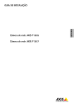
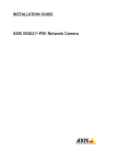
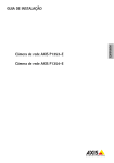
Installation Guide
ENGLISH
AXIS Q3505–V Fixed Dome Network Camera
Legal Considerations
Regulatory Information
Video and audio surveillance can be regulated by laws that
vary from country to country. Check the laws in your local
region before using this product for surveillance purposes.
This product includes one (1) H.264 decoder license and
one (1) AAC decoder license. To purchase further licenses,
contact your reseller.
Europe
Liability
Every care has been taken in the preparation of this
document. Please inform your local Axis office of any
inaccuracies or omissions. Axis Communications AB cannot
be held responsible for any technical or typographical errors
and reserves the right to make changes to the product and
manuals without prior notice. Axis Communications AB
makes no warranty of any kind with regard to the material
contained within this document, including, but not limited
to, the implied warranties of merchantability and fitness for
a particular purpose. Axis Communications AB shall not
be liable nor responsible for incidental or consequential
damages in connection with the furnishing, performance
or use of this material. This product is only to be used for
its intended purpose.
Intellectual Property Rights
Axis AB has intellectual property rights relating to
technology embodied in the product described in this
document. In particular, and without limitation, these
intellectual property rights may include one or more of
the patents listed at www.axis.com/patent.htm and one or
more additional patents or pending patent applications in
the US and other countries.
This product contains licensed third-party software. See
the menu item “About” in the product’s user interface for
more information.
This product contains source code copyright Apple Computer,
Inc., under the terms of Apple Public Source License 2.0
(see www.opensource.apple.com/apsl). The source code is
available from https://developer.apple.com/bonjour/
Equipment Modifications
This equipment must be installed and used in
strict accordance with the instructions given in the
user documentation. This equipment contains no
user-serviceable components. Unauthorized equipment
changes or modifications will invalidate all applicable
regulatory certifications and approvals.
Trademark Acknowledgments
AXIS COMMUNICATIONS, AXIS, ETRAX, ARTPEC and VAPIX
are registered trademarks or trademark applications of Axis
AB in various jurisdictions. All other company names and
products are trademarks or registered trademarks of their
respective companies.
Apple, Boa, Apache, Bonjour, Ethernet, Internet Explorer,
Linux, Microsoft, Mozilla, Real, SMPTE, QuickTime, UNIX,
Windows, Windows Vista and WWW are registered
trademarks of the respective holders. Java and all
Java-based trademarks and logos are trademarks or
registered trademarks of Oracle and/or its affiliates.
UPnPTM is a certification mark of the UPnPTM Implementers
Corporation.
SD, SDHC and SDXC are trademarks or registered trademarks
of SD-3C, LLC in the United States, other countries or both.
Also, miniSD, microSD, miniSDHC, microSDHC, microSDXC
are all trademarks or registered trademarks of SD-3C, LLC
in the United States, other countries or both.
This product complies with the applicable CE marking
directives and harmonized standards:
• Electromagnetic Compatibility (EMC) Directive
2004/108/EC. See Electromagnetic Compatibility (EMC)
on page 2 .
• Low Voltage (LVD) Directive 2006/95/EC. See Safety
on page 3 .
• Restrictions of Hazardous Substances (RoHS) Directive
2011/65/EU. See Disposal and Recycling on page 3 .
A copy of the original declaration of conformity may be
obtained from Axis Communications AB. See Contact
Information on page 3 .
Electromagnetic Compatibility (EMC)
This equipment has been designed and tested to fulfill
applicable standards for:
• Radio frequency emission when installed according to
the instructions and used in its intended environment.
• Immunity to electrical and electromagnetic phenomena
when installed according to the instructions and used
in its intended environment.
USA
This equipment has been tested using a shielded network
cable (STP) and found to comply with the limits for a
Class B digital device, pursuant to part 15 of the FCC
Rules. These limits are designed to provide reasonable
protection against harmful interference in a residential
installation. This equipment generates, uses and can
radiate radio frequency energy and, if not installed and
used in accordance with the instructions, may cause
harmful interference to radio communications. However,
there is no guarantee that interference will not occur in
a particular installation. If this equipment does cause
harmful interference to radio or television reception, which
can be determined by turning the equipment off and on,
the user is encouraged to try to correct the interference by
one or more of the following measures:
• Reorient or relocate the receiving antenna.
• Increase the separation between the equipment and
receiver.
• Connect the equipment into an outlet on a circuit
different from that to which the receiver is connected.
• Consult the dealer or an experienced radio/TV
technician for help.
The product shall be connected using a shielded network
cable (STP) that is properly grounded.
Canada
This Class B digital apparatus complies with Canadian
ICES-003. The product shall be connected using a shielded
network cable (STP) that is properly grounded.
Cet appareil numérique de la classe B est confome à la
norme NMB-003 du Canada. Le produit doit être connecté
à l'aide d'un câble réseau blindé (STP) qui est correctement
mis à la terre.
Europe
This digital equipment fulfills the requirements for RF
emission according to the Class B limit of EN 55022. The
product shall be connected using a shielded network cable
(STP) that is properly grounded.
This product fulfills the requirements for emission and
immunity according to EN 50121-4 and IEC 62236-4 railway
applications.
This product fulfills the requirements for immunity
according to EN 61000-6-1 residential, commercial and
light-industrial environments.
This product fulfills the requirements for immunity
according to EN 61000-6-2 industrial environments.
This product fulfills the requirements for immunity
according to EN 55024 office and commercial environments
Australia/New Zealand
This digital equipment fulfills the requirements for RF
emission according to the Class B limit of AS/NZS CISPR 22.
The product shall be connected using a shielded network
cable (STP) that is properly grounded.
Japan
この装置は、クラスB 情報技術装置です。この装置
は、家庭環境で使用することを目 的としています
が、この装置がラジオやテレビジョン受信機に近
接して使用されると、 受信障害を引き起こすこと
があります。 取扱説明書に従って正しい取り扱い
をして下さい。 本製品は、シールドネットワーク
ケーブル(STP)を使用して接続してください。また
適切に接地してください。
Korea
이 기기는 가정용(B급) 전자파적합기기로서 주로
가정에서 사용하는 것을 목적으로 하며, 모든 지
역에서 사용할 수 있습니다. 적절히 접지된 STP
(shielded twisted pair) 케이블을 사용하여 제품
을 연결 하십시오.
Safety
This product complies with IEC/EN/UL 60950-1, Safety of
Information Technology Equipment. If its connecting cables
are routed outdoors, the product shall be grounded either
through a shielded network cable (STP) or other appropriate
method.
Disposal and Recycling
When this product has reached the end of its useful life,
dispose of it according to local laws and regulations. For
information about your nearest designated collection point,
contact your local authority responsible for waste disposal.
In accordance with local legislation, penalties may be
applicable for incorrect disposal of this waste.
Europe
This symbol means that the product shall not be
disposed of together with household or commercial waste.
Directive 2012/19/EU on waste electrical and electronic
equipment (WEEE) is applicable in the European Union
member states. To prevent potential harm to human health
and the environment, the product must be disposed of in
an approved and environmentally safe recycling process.
For information about your nearest designated collection
point, contact your local authority responsible for waste
disposal. Businesses should contact the product supplier for
information about how to dispose of this product correctly.
This product complies with the requirements of
Directive 2011/65/EU on the restriction of the use of
certain hazardous substances in electrical and electronic
equipment (RoHS).
China
This product complies with the requirements of the
legislative act Administration on the Control of Pollution
Caused by Electronic Information Products (ACPEIP).
Contact Information
Axis Communications AB
Emdalavägen 14
223 69 Lund
Sweden
Tel: +46 46 272 18 00
Fax: +46 46 13 61 30
www.axis.com
Support
Should you require any technical assistance, please contact
your Axis reseller. If your questions cannot be answered
immediately, your reseller will forward your queries through
the appropriate channels to ensure a rapid response. If you
are connected to the Internet, you can:
• download user documentation and software updates
• find answers to resolved problems in the FAQ database.
Search by product, category, or phrase
• report problems to Axis support staff by logging in to
your private support area
• chat with Axis support staff (selected countries only)
• visit Axis Support at www.axis.com/techsup/
Learn More!
Visit Axis learning center www.axis.com/academy/ for
useful trainings, webinars, tutorials and guides.
AXIS Q3505–V Fixed Dome Network Camera
Safety Information
Read through this Installation Guide carefully before installing the product. Keep the Installation
Guide for future reference.
Hazard Levels
Indicates a hazardous situation which, if not avoided, will result in
death or serious injury.
WARNING
Indicates a hazardous situation which, if not avoided, could result
in death or serious injury.
CAUTION
Indicates a hazardous situation which, if not avoided, could result
in minor or moderate injury.
NOTICE
TICE
NO
Indicates a situation which, if not avoided, could result in damage
to property.
Other Message Levels
Important
Indicates significant information which is essential for the product
to function correctly.
Note
Indicates useful information which helps in getting the most out
of the product.
5
ENGLISH
DANGER
AXIS Q3505–V Fixed Dome Network Camera
Safety Instructions
NOTICE
TICE
NO
• The Axis product shall be used in compliance with local laws and regulations.
• To use the Axis product outdoors, or in similar environments, it shall be installed in an
approved outdoor housing.
• Store the Axis product in a dry and ventilated environment.
• Avoid exposing the Axis product to shocks or heavy pressure.
• Do not install the product on unstable brackets, surfaces or walls.
• Use only applicable tools when installing the Axis product. Excessive force could cause
damage to the product.
• Do not use chemicals, caustic agents, or aerosol cleaners. Use a clean cloth dampened
with pure water for cleaning.
• Use only accessories that comply with technical specification of the product. These can be
provided by Axis or a third party.
• Use only spare parts provided by or recommended by Axis.
• Do not attempt to repair the product by yourself. Contact Axis support or your Axis
reseller for service matters.
Transportation
NOTICE
TICE
NO
• When transporting the Axis product, use the original packaging or equivalent to prevent
damage to the product.
Battery
The Axis product uses a 3.0 V BR/CR2032 lithium battery as the power supply for its internal
real-time clock (RTC). Under normal conditions this battery will last for a minimum of five years.
Low battery power affects the operation of the RTC, causing it to reset at every power-up. When
the battery needs replacing, a log message will appear in the product’s server report. For more
information about the server report, see the product´s setup pages or contact Axis support.
The battery should not be replaced unless required, but if the battery does need replacing, contact
Axis support at www.axis.com/techsup for assistance.
6
AXIS Q3505–V Fixed Dome Network Camera
WARNING
• Risk of explosion if the battery is incorrectly replaced.
• Replace only with an identical battery or a battery which is recommended by Axis.
• Dispose of used batteries according to local regulations or the battery manufacturer's
instructions.
Dome Cover
• Do not clean a dome cover that looks clean to the eye and never polish the surface.
Excessive cleaning could damage the surface.
• For general cleaning of the dome cover it is recommended to use a non-abrasive,
solvent-free neutral soap or detergent mixed with pure water and a soft, clean cloth. Rinse
well with pure lukewarm water. Dry with a soft, clean cloth to prevent water spotting.
• Never use harsh detergents, gasoline, benzene or acetone etc. and avoid cleaning the
dome cover in direct sunlight or at elevated temperatures.
7
ENGLISH
NOTICE
TICE
NO
• Be careful not to scratch, damage or leave fingerprints on the dome cover because this
could decrease image quality. If possible, keep the protective plastic on the dome cover
until the installation is complete.
8
AXIS Q3505–V Fixed Dome Network Camera
Installation Guide
This Installation Guide provides instructions for installing AXIS Q3505 Fixed Dome Network
Camera on your network. For other aspects of using the product, see the User Manual available
at www.axis.com
Installation Steps
Package Contents
For optional accessories see axis.com
•
•
•
•
•
•
AXIS Q3505–V Fixed Dome Network Camera
Secure Torx L- key
I/O connector
Extra cable gaskets
Cable Gasket M20
Cable Gasket M20–3mm
Installation and Management Software CD
Printed materials
Installation Guide (this document)
Drill template (2x)
Extra serial number label (2x)
AVHS Authentication key
Recommended Tools
•
Resitorx key TR20
9
ENGLISH
1. Make sure the package contents, tools and other materials necessary for the installation
are in order. See page 9 .
2. Study the hardware overview. See page 10.
3. Study the specifications. See page 13.
4. Install the hardware. See page 16.
5. Access the product. See page 19.
AXIS Q3505–V Fixed Dome Network Camera
Hardware Overview
Note
3–9 mm lens: Pressing the lens too hard while cleaning may cause the lens to move
down. If this happens while the camera is in operation, re-calibrate the optics by clicking
Calibrate from the Server Maintenance web page (System Options > Maintenance).
1 2 3 4 5
6
15 16
7
11
8 9
10
12
13
14
1.
2.
3.
4.
5.
6.
7.
8.
9.
10.
11.
12.
13.
14.
Network connector
Control button
I/O connector
Audio out
Audio in
SD card slot
AC/DC connector for power accessory (outdoor model only)
Mounting bracket
Side lid
Locking clip
Network cable
Unit casing
Camera unit
Dome cover
10
AXIS Q3505–V Fixed Dome Network Camera
15. Status LED
16. Function button
LED Indicators
Color
Indication
Status
Unlit
Connection and normal operation
Amber
Steady during startup. Flashes during firmware upgrade.
Amber/red
Flashes amber/red if network connection is unavailable
or lost.
Red
Flashes red for firmware upgrade failure.
Green
Shows steady green for 10 seconds for normal operation
after restart.
Note
• The Status LED can be configured to flash while an event is active.
• The Status LED can be configured to flash for identifying the unit. Go to Setup > System
Options > Maintenance .
Status LED Behavior and Buzzer Signal for Levelling Assistant
For information on the Function button used for levelling the camera, see Connectors and Buttons.
Color
Buzzer
Camera position
Fixed green
Continuous beep
Level
Flashing green
Fast interval
Almost level
Flashing orange
Medium interval
Not level
Flashing red
Slow interval
Far from level
Connectors and Buttons
For specifications and operating conditions, see page 13.
Network Connector
RJ45 Ethernet connector with Power over Ethernet (PoE).
11
ENGLISH
LED
AXIS Q3505–V Fixed Dome Network Camera
NOTICE
TICE
NO
The product shall be connected using a shielded network cable (STP) or an optical fiber
cable. All cables connecting the product to the network shall be intended for their
specific use. Make sure that the network devices are installed in accordance with
the manufacturer’s instructions. For information about regulatory requirements, see
Electromagnetic Compatibility (EMC) on page 2 .
I/O Connector
Use with external devices in combination with, for example, tampering alarms, motion detection,
event triggering, time lapse recording and alarm notifications. In addition to the 0 V DC reference
point and power (DC output), the I/O connector provides the interface to:
•
•
Digital output – For connecting external devices such as relays and LEDs. Connected
devices can be activated by the VAPIX® Application Programming Interface, output
buttons on the Live View page or by an Action Rule. The output will show as active
(shown under System Options > Ports & Devices) if the alarm device is activated.
Digital input – An alarm input for connecting devices that can toggle between an open
and closed circuit, for example: PIRs, door/window contacts, glass break detectors,
etc. When a signal is received the state changes and the input becomes active (shown
under System Options > Ports & Devices).
Audio Connector
The Axis product has the following audio connectors:
•
•
Audio in (pink) – 3.5 mm input for a mono microphone, or a line-in mono signal (left
channel is used from a stereo signal).
Audio out (green) – 3.5 mm output for audio (line level) that can be connected to
a public address (PA) system or an active speaker with a built-in amplifier. A stereo
connector must be used for audio out.
SD Card Slot
A microSD card (not included) can be used for local recording with removable storage. For more
information, see Specifications on page 13.
NOTICE
TICE
NO
To prevent corruption of recordings, the SD card should be unmounted before removal. To
unmount, go to Setup > System Options > Storage > SD Card and click Unmount.
Control Button
The control button is used for:
12
AXIS Q3505–V Fixed Dome Network Camera
•
•
Resetting the product to factory default settings. See page 20.
Connecting to an AXIS Video Hosting System service or AXIS Internet Dynamic DNS
Service. For more information about these services, see the User Manual.
Function Button
The function button has multiple functions:
•
Multicable (sold separately)
The multicable can be purchased from an Axis reseller for connecting external equipment to the
Axis product. The cable provides the following connectors:
Audio connector - See Connectors on page 14
I/O connector - See Connectors on page 14
Power connector - Connector for AC and DC power for connection to the AXIS T8051 Power
Converter AC/DC to DC (not included) wires.
Wires
Specifications
Red
+ DC or AC
Black
– DC or AC
Specifications
This Axis product is intended for indoor use.
Product
Classification
Temperature
Humidity
AXIS Q3505–V
IEC 60529 IP52
–10 °C to 50 °C
(14 °F to 122 °F)
10-85% RH (non-condensing)
13
ENGLISH
•
As Levelling Assistant – This function helps to ensure the camera is level. Press the
button for about 2 seconds to start the levelling assistant and press again to stop. The
status LED (see page 11 ) and buzzer signal assist levelling of the camera. The camera is
level when the buzzer beeps continuously.
To view the Status LED – Press the button once to light up the Status LEDs. Press again
to turn them off. The LEDs will turn off automatically after 10 seconds.
AXIS Q3505–V Fixed Dome Network Camera
Connectors
I/O Connector
4–pin terminal block for:
•
•
•
•
Auxiliary power (DC output)
Digital Input
Digital Output
0 V DC (-)
1
2
3
4
Function
Pin
Notes
0 V DC (-)
1
DC output
2
Can be used to power auxiliary equipment.
Note: This pin can only be used as power out.
12 V D C
Max load = 50 mA
Configurable
(Input or
Output)
3–
4
Digital input – Connect to pin 1 to activate,
or leave floating (unconnected) to deactivate.
0 to max 30 V DC
Digital output – Connected to pin 1 when
activated, floating (unconnected) when
deactivated. If used with an inductive load,
e.g. a relay, a diode must be connected in
parallel with the load, for protection against
voltage transients.
0 to max 30 V DC, open
drain, 100 mA
Specifications
0 V DC
14
AXIS Q3505–V Fixed Dome Network Camera
1
12 V max 50 mA
2
ENGLISH
3
4
3.
4.
I/O configured as input
I/O configured as output
Audio Connector
3.5 mm audio
connectors (stereo)
Audio
Input
3
2
1
1 Tip
2 Ring
3 Sleeve
Microphone/Line in
Balanced Microphone
Cold (-) In
Ground
Balanced Microphone
Hot (+) In/Unbalance
Microphone In/Line In
Audio
Output
Ground
Line out (mono)
15
AXIS Q3505–V Fixed Dome Network Camera
SD Card Slot
Supports microSD cards with up to 64 GB of storage. For best recording performance, use
a microSDHC UHS-I or microSDXC UHS-I card. In temperatures below – 25° C use industrial
grade SD card.
Install the Hardware
Mounting Bracket
The mounting bracket has 4 mounting patterns. The mounting patterns follow the standard for the
following mounting options:
•
: 4" square box
•
: standard-sized US double gang junction box
•
: 4" octagon box
•
: standard-sized US single gang junction box
Attach Mounting Bracket to Wall
1. Attach the mounting bracket (see Mounting Bracket on page 16) to the wall with
appropriate screws.
2. To route the cables see Route the Cables on page 17.
3. Wind the network cable along the grooves on the mounting bracket keeping the extra
cable length that may be required later.
16
AXIS Q3505–V Fixed Dome Network Camera
Route the Cables
ENGLISH
Note
See Hardware Overview on page 10.
Depending on whether you want to route the cables through or along the wall, follow the relevant
instructions below. To route cables through the wall:
1. Using the drill template drill 4 holes for mounting the bracket, and one or two holes as
required for routing the cable or cables in the wall.
2. Route the network cable (and the multicable if required) through the wall and through
the hole or holes in the mounting bracket.
The cables can be routed along the wall in one of the following ways:
1. Through the side hole in the mounting bracket. To do this detach the locking clip and
side lid in the mounting bracket. Use an appropriate conduit adaptor as required (see
www.axis.com for optional accessories). See Hardware Overview on page 10.
2. Through the side lid after drilling a hole in the lid for the cable. Replace the side lid and
clamp down the locking clip to hold it in place.
Connect the Cables and Attach Unit Casing to Mounting Bracket
1. Insert the SD memory card in the camera unit (optional).
2. Push the network cable through the black cable gasket in one of the holes in the unit
casing, using the connector guard provided. Pull the network cable back slightly so
that the cable gasket adjusts itself on the cable. It is recommended to route the cable
through the hole farthest from the network connector in the camera unit (see image
below).
17
AXIS Q3505–V Fixed Dome Network Camera
NOTICE
TICE
NO
Not pulling the cable back could cause water to seep in and damage the product.
3. Tighten the 4 tamper proof screws to attach the unit casing to the mounting bracket
using the Resitorx key TR20.
4. Connect the cable to the camera unit.
5. Pull the springs aside in the unit casing and attach camera unit to the unit casing.
Adjust Camera Angle
1
4
3
1.
2.
3.
4.
2
Lines on optic holder that indicate an increment in the tilt angle by 10°
Small lines on optic mount that indicate a pan increment of 3°
Lines on optic mount that indicate a pan increment of 15°
Lines on lens cover to help ensure camera is level
1. Pan, tilt and rotate the camera to cover the area under surveillance. It is possible to pan
360°, and tilt to an angle of 90°.
2. Pan and rotate the lens to adjust image. Use the 2 lines on the lens cover to ensure
the camera is level. Use the function button to activate levelling aid. See Function
Button on page 13.
18
AXIS Q3505–V Fixed Dome Network Camera
Attach Dome Cover
1. Make sure the gasket in the dome cover is clean and sits securely in place.
2. Slip the grooves in the black shield, over the screws on either side of the camera’s optic
holder. Align the screws in the dome cover with the holes in the unit casing and tighten
using the Resitorx key TR20.
3. Remove the protective film from the dome cover.
ENGLISH
Camera unit: AXIS Q3505–V
Access the Product
Use the tools provided on the Installation and Management Software CD to assign an IP address,
set the password and access the video stream. This information is also available from the support
pages on www.axis.com/techsup/
Focus & Zoom
This feature is only available when you have selected Optical zoom for installation.
To set focus and zoom:
1. Go to Video & Audio > Focus & Zoom.
2. On the Basic tab, set the zoom level using the slider. The buttons < and > move the zoom
position one step in either direction. The buttons << and >> move the zoom position in
multiple steps in either direction.
3. Click Perform auto focus to focus the camera automatically.
4. If more adjustments are needed, go to the Advanced tab.
Note
• Movements in front of the camera should be avoided during automatic focusing.
19
AXIS Q3505–V Fixed Dome Network Camera
On the Advanced tab, focus can be adjusted manually:
1. Click Open iris to open the iris to its maximum position. This gives the smallest depth of
field and provides the best conditions for focusing.
2. Focus is set in the Focus window. Use the mouse to move and resize the focus window.
3. Click in the Focus position bar to focus on a desired location. The buttons < and > move
the focus position one step in either direction. The buttons << and >> move the focus
position in multiple steps in either direction.
4. When satisfied, click Enable iris to enable the iris.
The Pixel counter shows the number of pixels in an area of the image and can be used to ensure
that the size of the image fulfills certain requirements, for example for face recognition. Use
the mouse to move and resize the pixel counter, or enter the number of pixels in the Width and
Height fields and click Apply.
Set Zoom and Focus - Optical Zoom for Monitoring
To set Focus & Zoom when you have selected Optical zoom for monitoring:
Go to PTZ > Preset Positions and follow the online instructions to set the focus. In order to be able
to retain this focus position after restarting the camera, enter a name for this preset in the Current
position field and select the Use current position as Home option. If you calibrate the optics
while in this Optical zoom for monitoring mode, select this preset from the Available positions
drop-down list in the Preset Positions webpage. Click Go to and Save.
To set limits for focus and zoom:
Go to Video & Audio > Focus & Zoom.
Select a Zoom tele limit value to limit the camera’s maximum zoom. The digital zoom level is
indicated with the letter D. To check the zoom tele limit, click Go to.
Set the Focus near limit to prevent the camera from focusing on objects that are too close.
It is possible to set focus and zoom from this page, but the focus will be lost when the camera is
restarted.
Reset to Factory Default Settings
Important
Reset to factory default should be used with caution. A reset to factory default will reset
all settings, including the IP address, to the factory default values.
20
AXIS Q3505–V Fixed Dome Network Camera
Note
The installation and management software tools are available on the CD supplied with the
product and from the support pages on www.axis.com/techsup
To reset the product to the factory default settings:
Further Information
The User Manual is available at www.axis.com
Visit www.axis.com/techsup to check if there is updated firmware available for your network
product. To see the currently installed firmware version, go to Setup > About.
Visit Axis learning center www.axis.com/academy for useful trainings, webinars, tutorials and
guides.
Warranty Information
For information about Axis’ product warranty and thereto related information, see
www.axis.com/warranty/
21
ENGLISH
1. Disconnect power from the product.
2. Press and hold the control button and reconnect power. See Hardware Overview on
page 10.
3. Keep the control button pressed for about 15–30 seconds until the status LED indicator
flashes amber.
4. Release the control button. The process is complete when the status LED indicator turns
green. The product has been reset to the factory default settings. If no DHCP server is
available on the network, the default IP address is 192.168.0.90
5. Using the installation and management software tools, assign an IP address, set the
password, and access the video stream.
It is also possible to reset parameters to factory default via the web interface. Go to Setup
> System Options > Maintenance.
Installation Guide
AXIS Q3505–V Fixed Dome Network Camera
© Axis Communications AB, 2014
Ver. M2.10
Date: April 2014
Part No. 54767