1
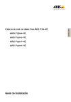
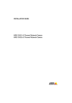
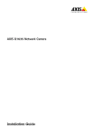
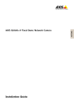
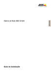
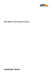
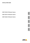
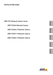
INSTALLATION GUIDE AXIS P3346-VE Network Camera AXIS P3367-VE Network Camera AXIS P3384-VE Network Camera Legal Considerations Video and audio surveillance can be prohibited by laws that vary from country to country. Check the laws in your local region before using this product for surveillance purposes. This product includes one (1) H.264 decoder license and one (1) AAC decoder license. To purchase further licenses, contact your reseller. Liability Every care has been taken in the preparation of this document. Please inform your local Axis office of any inaccuracies or omissions. Axis Communications AB cannot be held responsible for any technical or typographical errors and reserves the right to make changes to the product and manuals without prior notice. Axis Communications AB makes no warranty of any kind with regard to the material contained within this document, including, but not limited to, the implied warranties of merchantability and fitness for a particular purpose. Axis Communications AB shall not be liable nor responsible for incidental or consequential damages in connection with the furnishing, performance or use of this material. This product is only to be used for its intended purpose. Intellectual Property Rights Axis AB has intellectual property rights relating to technology embodied in the product described in this document. In particular, and without limitation, these intellectual property rights may include one or more of the patents listed at www.axis.com/patent.htm and one or more additional patents or pending patent applications in the US and other countries. This product contains licensed third-party software. See the menu item “About” in the product’s user interface for more information. This product contains source code copyright Apple Computer, Inc., under the terms of Apple Public Source License 2.0 (see www.opensource.apple.com/apsl). The source code is available from https://developer.apple.com/bonjour/ Equipment Modifications This equipment must be installed and used in strict accordance with the instructions given in the user documentation. This equipment contains no user-serviceable components. Unauthorized equipment changes or modifications will invalidate all applicable regulatory certifications and approvals. Trademark Acknowledgments AXIS COMMUNICATIONS, AXIS, ETRAX, ARTPEC and VAPIX are registered trademarks or trademark applications of Axis AB in various jurisdictions. All other company names and products are trademarks or registered trademarks of their respective companies. Apple, Boa, Apache, Bonjour, Ethernet, Internet Explorer, Linux, Microsoft, Mozilla, Real, SMPTE, QuickTime, UNIX, Windows, Windows Vista and WWW are registered trademarks of the respective holders. Java and all Java-based trademarks and logos are trademarks or registered trademarks of Oracle and/or its affiliates. UPnPTM is a certification mark of the UPnPTM Implementers Corporation. Regulatory Information Europe This product complies with the applicable CE marking directives and harmonized standards: • Electromagnetic Compatibility (EMC) Directive 2004/108/EC. See Electromagnetic Compatibility (EMC). • Low Voltage (LVD) Directive 2006/95/EC. See Safety. • Restrictions of Hazardous Substances (RoHS) Directive 2011/65/EU. See Disposal and Recycling. A copy of the original declaration of conformity may be obtained from Axis Communications AB. See Contact Information. Electromagnetic Compatibility (EMC) This equipment has been designed and tested to fulfill applicable standards for: • Radio frequency emission when installed according to the instructions and used in its intended environment. • Immunity to electrical and electromagnetic phenomena when installed according to the instructions and used in its intended environment. USA Using an unshielded network cable (UTP) - AXIS P3367-VE and AXIS P3384-VE have been tested using an unshielded network cable (UTP) and found to comply with the limits for a Class A digital device, pursuant to part 15 of the FCC Rules. These limits are designed to provide reasonable protection against harmful interference when the equipment is operated in a commercial environment. This equipment generates, uses, and can radiate radio frequency energy and, if not installed and used in accordance with the instruction manual, may cause harmful interference to radio communications. Operation of this equipment in a residential area is likely to cause harmful interference in which case the user will be required to correct the interference at his own expense. Using a shielded network cable (STP) – AXIS P3346-VE, AXIS P3367-VE and AXIS P3384-VE have been tested using a shielded network cable (STP) and found to comply with the limits for a Class B digital device, pursuant to part 15 of the FCC Rules. These limits are designed to provide reasonable protection against harmful interference in a residential installation. This equipment generates, uses and can radiate radio frequency energy and, if not installed and used in accordance with the instructions, may cause harmful interference to radio communications. However, there is no guarantee that interference will not occur in a particular installation. If this equipment does cause harmful interference to radio or television reception, which can be determined by turning the equipment off and on, the user is encouraged to try to correct the interference by one or more of the following measures: • Reorient or relocate the receiving antenna. • Increase the separation between the equipment and receiver. • Connect the equipment into an outlet on a circuit different from that to which the receiver is connected. • Consult the dealer or an experienced radio/TV technician for help. To be used in a residential area or a demanding electrical environment, the product shall be connected using a shielded network cable (STP) that is properly grounded. Canada This digital apparatus complies with CAN ICES-3 (Class B). The product shall be connected using a shielded network cable (STP) that is properly grounded. Cet appareil numérique est conforme à la norme CAN NMB-3 (classe B). Le produit doit être connecté à l'aide d'un câble réseau blindé (STP) qui est correctement mis à la terre. Europe This digital equipment fulfills the requirements for RF emission according to the Class B limit of EN 55022. The product shall be connected using a shielded network cable (STP) that is properly grounded. This product fulfills the requirements for immunity according to EN 61000-6-1 residential, commercial and light-industrial environments. This product fulfills the requirements for immunity according to EN 55024 office and commercial environments. Australia/New Zealand This digital equipment fulfills the requirements for RF emission according to the Class B limit of AS/NZS CISPR 22. The product shall be connected using a shielded network cable (STP) that is properly grounded. Japan - この装置は、クラスB 情報技術装置です。 この装置 は、家庭環境で使用することを目的として います が、この装置がラジオやテレビジョン受信機 に近 接して使用されると、受信障害を引き起こすこ と があります。取扱説明書に従って正しい取り扱い をして下さい。本製品は、シールドネットワーク ケーブル(STP)を使用して接続してください。また 適切に接地してください。 Korea - ࢇ̛̛Еɼࢽࡈ%̗ࢷળࢶଢ̛̛Ի۰ ࣯Իɼࢽ߾۰ࡈیଜЕʨࡶּࢶࡳԻଜֲֻҘ एࠇ߾۰ࡈیଟܹݡТЬࢶࢸࢻएѹ673 VKLHOGHGWZLVWHGSDLUৼࢇࡈیࡶٴଜࠆࢿ૽ ࡶࠉʼଜࠝݤݫ Safety This product complies with IEC/EN 60950-1, Safety of Information Technology Equipment. If its connecting cables are routed outdoors, the product shall be grounded either through a shielded network cable (STP) or other appropriate method. Disposal and Recycling When this product has reached the end of its useful life, dispose of it according to local raws and regulations. For information about your nearest designated collection point, contact your local authority responsible for waste disposal. In accordance with local legislation, penalties may be applicable for incorrect disposal of this waste. Europe This symbol means that the product shall not be disposed of together with household or commercial waste. Directive 2012/19/EU on waste electrical and electronic equipment (WEEE) is applicable in the European Union member states. To prevent potential harm to human health and the environment, the product must be disposed of in an approved and environmentally safe recycling process. For information about your nearest designated collection point, contact your local authority responsible for waste disposal. Businesses should contact the product supplier for information about how to dispose of this product correctly. This product complies with the requirements of Directive 2011/65/EU on the restriction of the use of certain hazardous substances in electrical and electronic equipment (RoHS). China This product complies with the requirements of the legislative act Administration on the Control of Pollution Caused by Electronic Information Products (ACPEIP). Contact Information Axis Communications AB Emdalavägen 14 223 69 Lund Sweden Tel: +46 46 272 18 00 Fax: +46 46 13 61 30 www.axis.com Support Should you require any technical assistance, please contact your Axis reseller. If your questions cannot be answered immediately, your reseller will forward your queries through the appropriate channels to ensure a rapid response. If you are connected to the Internet, you can: • download user documentation and software updates • find answers to resolved problems in the FAQ database. Search by product, category, or phrase • report problems to Axis support staff by logging in to your private support area • chat with Axis support staff (selected countries only) • visit Axis Support at www.axis.com/techsup/ Should you require any technical assistance, please contact appropriate channels according to your AVHS license agreement to ensure a rapid response. Learn More! Visit Axis learning center www.axis.com/academy/ for useful trainings, webinars, tutorials and guides. AXIS P33-VE Series Installation Guide Page 5 Safety Information Read through this Installation Guide carefully before installing the product. Keep the Installation Guide for future reference. Hazard Levels Indicates a hazardous situation which, if not avoided, will result in death or serious injury. Indicates a hazardous situation which, if not avoided, could result in death or serious injury. Indicates a hazardous situation which, if not avoided, could result in minor or moderate injury. Indicates a situation which, if not avoided, could result in damage to property. Other Message Levels Indicates significant information which is essential for the product to function correctly. Indicates useful information which helps in getting the most out of the product. Page 6 AXIS P33-VE Series Installation Guide Safety Instructions • The Axis product shall be installed by a trained professional. • • • • • • • • • The Axis product shall be used in compliance with local laws and regulations. Store the Axis product in a dry and ventilated environment. Avoid exposing the Axis product to shocks or heavy pressure. Do not install the product on unstable brackets, surfaces or walls. Use only applicable tools when installing the Axis product. Excessive force could cause damage to the product. Do not use chemicals, caustic agents, or aerosol cleaners. Use a clean cloth dampened with pure water for cleaning. Use only accessories that comply with technical specification of the product. These can be provided by Axis or a third party. Use only spare parts provided by or recommended by Axis. Do not attempt to repair the product by yourself. Contact Axis support or your Axis reseller for service matters. Transportation • Keep the protective packaging. When transporting the Axis product, the protective packaging shall be replaced in its original position. • When transporting the Axis product, use the original packaging or equivalent to prevent damage to the product. AXIS P33-VE Series Installation Guide Page 7 Battery The Axis product uses a 3.0 V BR/CR2032 lithium battery as the power supply for its internal realtime clock (RTC). Under normal conditions this battery will last for a minimum of five years. Low battery power affects the operation of the RTC, causing it to reset at every power-up. When the battery needs replacing, a log message will appear in the product’s server report. For more information about the server report, see the product’s setup pages or contact Axis support. The battery should not be replaced unless required, but if the battery does need replacing, contact Axis support at www.axis.com/techsup for assistance. • Risk of explosion if the battery is incorrectly replaced. • Replace only with an identical battery or a battery which is recommended by Axis. • Dispose of used batteries according to local regulations or the battery manufacturer's instructions. Dome Cover • Be careful not to scratch, damage or leave fingerprints on the dome cover because this could decrease image quality. If possible, keep the protective plastic on the dome cover until the installation is complete. • Do not clean a dome cover that looks clean to the eye and never polish the surface. Excessive cleaning could damage the surface. • For general cleaning of the dome cover it is recommended to use a non-abrasive, solvent-free neutral soap or detergent mixed with pure water and a soft, clean cloth. Rinse well with pure lukewarm water. Dry with a soft, clean cloth to prevent water spotting. • Never use harsh detergents, gasoline, benzene or acetone etc and avoid cleaning the dome cover in direct sunlight or at elevated temperatures. Page 8 AXIS P33-VE Series Installation Guide Installation Guide This guide helps you to install the AXIS P33-VE Series on your network. For further information, please see the User Manual available on the CD, or from www.axis.com/techsup Follow these instructions to install the network camera 1. 2. 3. 4. 5. 6. Package Contents, on page 9 Hardware Overview, on page 10 Install the Hardware, on page 15 Access the Product, on page 20 Adjust the Lens, on page 20 Complete the Installation, on page 22 Important! This product must be used in compliance with local laws and regulations. • Before you begin, make sure that the package contents, power supply, and the required cables, tools, and documentation are available. See Package Contents below. • This network camera is intended to operate with PoE; if not available use Axis PoE Midspan 1 port (not included) AXIS P33-VE Series Installation Guide Page 9 Package Contents Item Models/variants/notes Network camera with heating module AXIS P3346-VE AXIS P3367-VE AXIS P3384-VE Mounting bracket Dome covers Clear transparent cover Smoked transparent cover Weather shield Labels 2 adhesive serial no. labels Mounting kit Resitorx screw driver, drill template, 5-meter network cable with gasket 4 screws and plugs, 2 long screws, 2 M4x8 screws 1 gasket, terminal block connector CD AXIS Network Video Product CD including product documentation, installation tools and other software Printed Materials Installation Guide (this document) Axis Warranty Document AVHS Authentication key Optional accessories See www.axis.com for information on available accessories Page 10 AXIS P33-VE Series Installation Guide Hardware Overview Camera unit Heater I/O connector Network connector (PoE) Control button LED indicators Audio out Audio in Mounting bracket Unit casing Spring SD memory card slot Camera unit Dome cover Weather shield Holes for cables routed through the wall Serial no. Fan output Side holes with connector gaskets for cables routed along the wall The heater in the camera unit may be hot. Dimension (HxW) AXIS P3346-VE = 117 x 179 mm (4.59” x 7.05”) AXIS P3367-VE = 117 x 179 mm (4.59” x 7.05”) AXIS P3384-VE = 117 x 179 mm (4.59” x 7.05”) Weight AXIS P3346-VE = 1.6 kg (3.5 lb) AXIS P3367-VE = 1.6 kg (3.5 lb) AXIS P3384-VE = 1.6 kg (3.5 lb) AXIS P33-VE Series Installation Guide Page 11 LED Indicators LED Color Indication Network Green Steady for connection to a 100 Mbit/s network. Flashes for network activity. Status Power Amber Steady for connection to 10 Mbit/s network. Flashes for network activity. Unlit No network connection. Green Steady green for normal operation. Amber Steady during startup; flashes once during reset to factory default or while restoring settings. Red Slow flash for failed upgrade. Green Normal operation. Amber Flashes green/amber during firmware upgrade. Page 12 AXIS P33-VE Series Installation Guide Connectors Network Connector AXIS P3367-VE and AXIS AXIS P3384-VE: Due to local regulations or the environmental and electrical conditions in which the product is to be used, a shielded network cable (STP) may be appropriate or required. All cables connecting the product to the network and that are routed outdoors or in demanding electrical environments shall be intended for their specific use. Make sure that the network devices are installed in accordance with the manufacturer’s instructions. For information about regulatory requirements, see Regulatory Information, on page 2. AXIS P3346-VE: The product shall be connected using a shielded network cable (STP). All cables connecting the product to the network shall be intended for their specific use. Make sure that the network devices are installed in accordance with the manufacturer’s instructions. For information about regulatory requirements, see Regulatory Information, on page 2. • RJ-45 Ethernet connector. Supports Power over Ethernet. Audio Connectors • • Audio in - 3.5mm input for a mono microphone, or a line-in mono signal (left channel is used from a stereo signal). Audio out - Audio output (line level) that can be connected to a public address (PA) system or an active speaker with a built-in amplifier. A pair of headphones can also be attached. A stereo connector must be used for the audio out. SD Card Slot • SDHC memory card slot - The high capacity SD memory card can be used for local recording with removable storage. AXIS P33-VE Series Installation Guide Page 13 I/O Connectors • • • I/O terminal connector - Used in applications for e.g. motion detection, event triggering, time lapse recording and alarm notifications. In addition to an auxiliary power and a GND pin, it provides the Pin4 Pin2 interface to: Pin3 Pin1 1 transistor output - For connecting external devices such as relays and LEDs. Connected devices can be activated by the VAPIX® Application Programming Interface (API), by the output buttons on the Live View page or by an Action Rule. The output will show as active (shown under System Options > Ports & Devices) if the alarm device is activated. 1 digital input - An alarm input for connecting devices that can toggle between an open and closed circuit, for example: PIRs, door/window contacts, and glass break detectors. When a signal is received the state changes and the input becomes active (shown under System Options > Ports & Devices). Function Pin Notes Specifications GND 1 Ground 3.3V DC Power 2 Can be used to power auxiliary equipment. Note: This pin can only be used as power out. Max. load = 50mA Digital Input 3 Connect to GND to activate, or leave floating (or unconnected) to deactivate. Min. input= - 40V DC Max. input= + 40V DC Digital Output 4 Uses an open-drain NFET transistor with the source connected to GND. If used with an external relay, a diode must be connected in parallel with the load, for protection against voltage transients. Max. load = 100mA Max voltage = + 40V DC Page 14 AXIS P33-VE Series Installation Guide The following connection diagram gives an example of how to connect an auxiliary device to the AXIS P3346-VE/P3367-VE/P3384-VE. 1 E.g. push button 3.3V max. 50mA 2 3 D G S 4 AXIS P33-VE Series Installation Guide Page 15 Install the Hardware Please remove the rubber band for transport-safety from the camera unit before you mount the camera. Prepare the Network Cable For network cable specifications, see Network Connector, on page 12. If a cable other than the provided cable is used, you need to prepare a network cable with a gasket. Gently force the cable through the gasket provided and attach a network connector. It may be necessary to pierce a hole in the gasket with the resitorx screwdriver. • Do not force the network connector into the gasket. • Do not pierce the gasket with a knife or other sharp object. Page 16 AXIS P33-VE Series Installation Guide Prepare the Unit Casing (routing cables along the wall) If the cables are to be routed along the wall, prepare the unit casing as follows: 1. Detach the side lid that is attached to the unit casing by removing the screw. 2. Loosen the two screws on the cable shield and detach the bottom part. 3. Attach the bottom part of the cable shield to the unit casing with the screw. Unit casing Screw Side lid Cable shield Unit casing Top part Bottom part Replace Clear/Smoked Dome Cover (optional) The AXIS P3346-VE/P3367-VE/P3384-VE is supplied with an optional dome. To replace the dome cover: 1. Loosen the 4 screws under the dome cover that hold the dome in place. 2. Replace the old dome with the new and tighten the screws. Mounting Bracket The mounting plate has 4 mounting hole patterns (A,B,C,D). The mounting hole patterns follow standard for the following mounting options: • A: 4" square box • B: standard-sized US double gang junction box • C: 4" octagon box • D: standard-sized US single gang junction box AXIS P33-VE Series Installation Guide Page 17 Route the Cables Depending on whether you want to route the cables through or along the wall, follow the relevant instructions below. Routing Cables along the Wall 1. Using the drill template drill 4 holes in the wall. 2. Attach the mounting bracket to the wall using the 4 screws provided, or screws appropriate for the wall material. 3. Remove the camera unit from the unit casing by pushing the springs aside. 4. Remove the gaskets from the side holes in the unit casing. If there is only one cable, remove only one gasket. 5. Place the unit casing on the mounting bracket and attach it by tightening the four screws. 6. Pull the cables up through the side holes in the unit casing. 7. Drag the gaskets along the cable and plug them into the holes. The gaskets should fit snugly in the holes with no folds or bends. 8. Re-attach the top part of the cable shield by tightening the two screws. To avoid moisture-related problems it is recommended that the cables are routed to the camera from below with the cable holes facing downwards. Routing Cables through the Wall 1. Using the drill template drill 4 holes in the wall. 2. Route the network cable (and the I/O, audio cable if necessary) through the wall and through the holes in the mounting bracket. 3. Attach the mounting bracket to the wall using the 4 screws provided, or screws appropriate for the wall material. 4. Remove the camera unit from the unit casing by pushing the springs aside. 5. Remove the gaskets from the back holes in the unit casing. If there is only one cable, remove only one gasket. 6. Route the cables through these holes. 7. Drag the gaskets along the cables and plug them into the holes. The gaskets should fit snugly in the holes with no folds or bends. Page 18 AXIS P33-VE Series Installation Guide 8. Attach the unit casing to the mounting bracket by tightening the four screws. Remove gaskets from holes Mounting bracket Unit casing Network cable with gasket AXIS P33-VE Series Installation Guide Page 19 Install the Camera Unit Connector for fan Camera unit Attach screw to camera Network cable 1. Attach the network cable to the camera unit; and the cable for audio and I/O if required. It is recommended that the network cable is twisted to a loop as shown in the illustration above. Be careful not to stretch or bend the network cable too much since this could cause damage to the network cable. 2. 3. 4. 5. Insert the SD memory card (optional). Pull aside the springs in the unit casing and click the camera unit in place. Attach the fan connector to the connector in the camera unit. Attach the two M4x8 20 screws to the camera for greater stability. These screws are only necessary to secure against heavy shocks and vibrations. Page 20 AXIS P33-VE Series Installation Guide The AXIS P3346-VE/P3367-VE/P3384-VE can also be fitted with a metal conduit for protecting the cabling when cables are routed along the wall. Conduit AXIS P33-VE Series Installation Guide Page 21 Access the Product Use the tools provided on the Installation and Management Software CD to assign an IP address, set the password and access the video stream. This information is also available from the support pages on www.axis.com/techsup/ Adjust the Lens Adjusting the focus and zoom manually can damage the lens. Do not tilt the lens more than 90°, this may cause damage to the product. See the illustration below. If it is necessary to tilt more than 90°, do the following: 1. Loosen the pan screw. 2. Rotate the lens 180°. 3. Tilt the lens. Page 22 AXIS P33-VE Series Installation Guide Open the Live View page in the web interface and make the following adjustments to the camera: Horizontal line Tilt adjustment screw Tilt adjustment screw Locking screw 1. Loosen the locking screw and tilt adjustment screws. 2. Turn the lens (with the lens holder) to the desired position. Make sure the horizontal lines on either side of the lens are aligned horizontally Ensure that the mark on the lens cover, between the horizontal lines, is facing up. 3. Once satisfied, gently tighten the locking screw and tilt adjustment screws to secure the camera’s position. 4. Open the Focus Adjustment page in the Web interface under Setup > Basic Setup > Focus & Zoom, and follow the on-screen instructions. Use the image window to adjust the focus and zoom. See the online help files for more information. Due to the dome’s refraction, the image may appear slightly out of focus once the dome has been placed. To correct this go to the Focus Adjustment page in the Web interface under Setup > Basic Setup > Focus & Zoom, and adjust the focus again. AXIS P33-VE Series Installation Guide Page 23 Complete the Installation Black protective 1. Rotate the black protective shield inside the dome cover shield so it is aligned with the camera’s position. 2. If required, attach the weather shield to the camera before you attach the dome cover. To do this remove the two screws in the dome cover. Transfer the washers from these screws to the two long screws provided. Attach the weather shield using the two long screws. 3. Attach the dome cover to the unit casing by tightening the 4 screws. Page 24 AXIS P33-VE Series Installation Guide Reset to Factory Default Settings Reset to factory default should be used with caution. A reset to factory default will reset all settings, including the IP address, to the factory default values. The installation and management software tools are available on the CD supplied with the product and from the support pages on www.axis.com/techsup To reset all parameters and the IP address to Factory Default settings: 1. Disconnect the power from the product. 2. Press and hold the Control button and reconnect power. 3. Keep the Control button pressed for about 15-30 seconds until the Status LED indicator flashes amber. 4. Release the Control button. 5. When the Status indicator displays green (which can take up to 1 minute) the process is complete and the product has been reset to factory default settings. Using the installation and management software tools, assign an IP address, set the password, and access the video stream. Further information The user’s manual is available from the Axis web site at www.axis.com or from the Axis Network Video Product CD supplied with this product. Visit www.axis.com/techsup to check if there is updated firmware available for the AXIS P33-VE Series. To see the currently installed firmware version, see Setup > About in the camera’s web pages. Installation Guide AXIS P3346-VE/AXIS P3367-VE/AXIS P3384-VE © Axis Communications AB, 2014 Ver. 4.2 Printed: October 2014 Part No. 50609