1
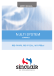
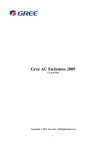
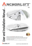
OPERATION
&
INSTALLATION
INSTRUCTIONS
FLOOR AND CEILING TYPE UNIT
GREE ELECTRIC APPLIANCES, INC. OF ZHUHAI
Read this operating & installation instruction carefully and keep it for future reference
MODEL
GTHD(09)AANK3A1AI
GTHD(12)AANK3A1AI
GTHD(18)AANK3A1AI
HEAT PUMP SYSTEM
CONTENTS
OPERATION INSTRUCTIONS
1.
Part names and their functions ........................................................................................................... 1
2.
How to use the remote control to operate the unit .............................................................................. 2
3.
Maintenance............................................................................................................................................11
4.
Operating guide................................................................................................................................. 12
5.
Precautions ....................................................................................................................................... 13
6.
Checking before contact the service man......................................................................................... 14
INSTALLATION INSTRUCTIONS
7.
Installation of Indoor unit .................................................................................................................... 15
8.
Refrigerant piping work ..................................................................................................................... 18
9.
DRAIN PIPING WORK ...................................................................................................................... 19
10. Test running ...................................................................................................................................... 20
11. ROUTINE CHECK AFTER INSTALLATION..................................................................................... 21
12. FAULT INDICATION......................................................................................................................... 22
1
PART NAMES AND THEIR FUNCTIONS
Remote Control
Remote Control Holder
1
OPERATION INSTRUCTIONS
2
How to use the remote control to operate the unit
OPERATION INSTRUCTIONS
Name and Function-Remote control
Note:
Be sure that there are no obstructions between receiver and remote controller.
Don’t drop or throw the remote controller.
Don’t let any liquid in the remote controller and put the remote controller
directly under the sunlight or any place where is very hot.
SWING button
When it is pressed, the louvers
start to rotate automatically and
stop when repressed.
FAN button
Press this button to change
the fan speed of:
TEMP. button
by
SET TEMP. increases 1
pressing
button once,and decreases 1 by pressing button
once.
At COOL mode operation, SET
TEMP. can be selected from 16
to 30 .
At DRY mode operation, SET
TEMP. can be selected from 16
to 30 .
At HEAT mode operation, SET
TEMP. can be selected from 16
to 30 .
“
“
“
“
” COOL mode
” DRY mode
” FAN mode
” HEAT mode
ON/OFF button
Press this button to turn
on or turn off the unit.
MODE button
press this button to change the
operation mode in order of:
AUTO
2
How to use the remote control to operate the unit
OPERATION INSTRUCTIONS
Name and Function-Remote control. (Remove the cover)
Note:
This type of remote controller is a kind of new current controller.
some buttons of the controller which are not available to this Air conditioner will not be described below.
Operate on unmentioned buttons would not impact on the normal use.
Liquid crystal displayer. It
shows all set contents.
SLEEP button
Press this button to set SLEEP
operation, and stop when repressed
TIMER OFF button
At operating, press TIMER
OFF button, set OFF TIME
in range of 0 to 24 hour to
stop the unit automatically.
0
24h
Timer
cancellation
TIMER ON button
At stopping, press TIMER ON button,
set ON TIME in range of 0 to 24 hour
at the interval of 0.5h to start the unit
automatically.
0
24h
Timer
cancellation
3
How to use the remote control to operate the unit
OPERATION INSTRUCTIONS
COOL mode operation procedure
According to difference between room temp. and set temp., microcomputer can control
cooling on or not.
If room temp. is higher than set temp., compressor runs at COOL mode.
If room temp. is lower than set temp., compressor stops and only indoor fan motor runs.
SET TEMP. should be in range of 16
to 30
4.Press FAN button, set
fan speed.
3.Press SWING button,
the louvers start to rotate automatically, and
stop when repress.
5.Press TEMP. button, set suitable SET
TEMP.
2.Press MODE button,
set
operation
mode.
1.Plug in, press ON/OFF button,then air
conditioner is turned on.
4
How to use the remote control to operate the unit
OPERATION INSTRUCTIONS
HEAT mode operation procedure
If room temp. is lower than set temp, compressor runs at HEAT mode;
If room temp. is higher than set temp., compressor and outdoor fan motor stop.
SET TEMP. should be in range of 16
to 30
3.Press SWING button, the
louvers start to rotate
automatically, and stop
when repress it.
4.Press FAN button, set
fan speed.
5.Press TEMP. button, set
suitable SET TEMP.
1.Plug in, press ON/OFF
button,then air conditioner is turned on.
2.Press MODE button,
set
The unit (cool only) do not receive the
control signal which is used under the
heat mode.
5
operation mode.
How to use the remote control to operate the unit
OPERATION INSTRUCTIONS
DRY mode operation procedure
If room temp. is lower than set temp., compressor ,outdoor fan motor stop. If room temp. is
2
of set temp., air conditioner is drying.If room temp. is higher than set
between
temp, it’s at COOL mode.
SET TEMP. should be in range of 16
to 30
3.Press SWING button,
the louvers start to rotate automatically, and
stop when repress it.
4.Press TEMP. button,set
suitable SET TEMP.
2.Press MODE button,set
operation mode.
Air speed couldn’t be
changed after the
being set.
1.Plug in,pressON/OFF button,then
air conditioner is turned on.
6
How to use the remote control to operate the unit
OPERATION INSTRUCTIONS
AUTO mode operation procedure
Under Auto mode operation, standard SET TEMP. is 25
HEAT mode.
for COOL mode and 20
1.Plug in,press ON/OFF button, then
air conditioner is turned on.
2.According to room temp. microcomputer can automatically set
operation mode,so
as for best effect.
7
for
How to use the remote control to operate the unit
OPERATION INSTRUCTIONS
TIMER mode operation procedure
At stopping,press TIMER ON
button, set ON TIME in
range of 0 to 24 hour to start
the unit automatically.
0
24h
Timer
cancellation
At operating,press TIMER
OFF button, set OFF TIME
in range of 0 to 24 hour to stop
the unit automatically.
0
24h
Timer
cancellation
8
How to use the remote control to operate the unit
OPERATION INSTRUCTIONS
SLEEP mode operation procedure
As the unit is cooling or drying, if SLEEP operation is set, SET TEMP. would increase 1
in 1 hour and 2 in 2 hours.
As the unit is heating, if SLEEP operation is set, SET TEMP. would decrease 1
and 2
in 1 hour
in 2 hours.
4.Press FAN button, set
fan speed.
3.Press SWING button,
the louvers start to rotate automatically, and
stop when repress.
6.SLEEP button
Press it to set SLEEP
operation.
5.Press TEMP. button, set suitable
SET TEMP.
2.Press MODE button,
or
opset
eration mode.
1.Plug in, press ON/OFF button,then
air conditioner is turned on.
9
How to use the remote control to operate the unit
OPERATION INSTRUCTIONS
How to insert batteries
1.Remove the cover from the back
of the remote control.
2.Insert the two batteries ( Two AAA
dry - cell batteries ) and press button “ACL”.
3.Re - attach the cover.
NOTE:
Don’t confuse the new
and worn or different
types of batteries.
Remove batteries when
the remote controller is
not in use for a
longtime.
The lifetime of the batteries is about one year.
The remote controller
should be placed about
1m or more away from
the TV. or any other
electric appliances.
2. Insert the TWO AAA batteries
Bad batteries are forbidden
1.Remove the cover
3.Re - attach the cover.
10
3
MAINTENANCE
OPERATION INSTRUCTIONS
WARNING:Before inspection and maintenance of the unit, always set the power switch to "OFF"
to cut off the power supply.
3.1 CLEANING THE AIR FILTERS
WARNING
The air filter must be cleaned by
profressional.
3.2 CLEANING THE UNIT THE ENCLOSURE
Clean the enclosure of the air conditioner and
the remote control with dry cloth or a vacuum
cleaner.If damp cloth is used, remove molsture
by using dry cloth afterward.
CAUTION
Do not use benzine gasoline, thinners or polishing
products for cleaning.
Do not wash with not water(above 40 ),Some parts
of the unit may be deformed.
3.3 AT THE START OF THE SEASON
3.4 DURING THE OFF SEASON
Check that nothing blocks the air inlet and
outlet of the indoor and outdoor units.
Cut off the power supply main switch.
Clean the enclosure.
Leave the fan running for 2-3 hours to dry
out the inside of the unit.
Running the unit without air filters can
cause malfunctions due to dirt or dust.
Always install air filters at all times.
Check that drainage hose is not bent or
clogged.
Check that the units are properly installed.
11
4
OPERATING GUIDE
OPERATION INSTRUCTIONS
●The temperature should not be set
●To disribute cool air throughout the room,
lower than what you need.This would
adjust air flow directionas shown by the
lead to increase energy cost.
arrows (see picture)to diffuse cool air.
●In case of ineffective ventilation,open the window
●Close window and door while operating
the unit to prevent leakage of cooled
to ventilate the room air once in a while but not too
air and save energy.
long since cooled air will be uselessly dirained out.
●Draw close curtains or close glass windows
when cooling to prevent heat load from sun
light which may cause more electricity cost.
12
5
PRECAUTIONS
OPERATION INSTRUCTIONS
●Turn off the air conditioner if,while running,
●Do not locate any obstacle against the air flow
electricity interference occurs,if the unit is
not to be used for a long time,cut off the
power supply main switch.
direction of indoor and outdoor unit.Inefficient
performance or malfunction may result.
●Do not channel the air flow directly at people,
●Do not loate a heater or any oter heat source
close to the unit.The heat may deform plastic parts.
especially infants,aged persons,or patients.
●Do not insert objects into the air inlet or
● WARNING:The appliance should
outlet when the air conditioner is running as
it may cause damage or personal injury.Also
pay special attention when children are around.
not be used by children without
supervisor.
13
6
●
CHECKING BEFORE CONTACT THE SERVICE MAN
OPERATION INSTRUCTIONS
Check the following before contacting the service man.You may find
the solution to your problems.After checking,if it still does not
operate, please contact your local dealer.
PROBLEM
CAUSES
● Check if breaker switch is still on.
No operation
● Check if the timer switch is on or not.
● Check if the preset temperature is too high.
The air conditioner runs
but does not cool enough.
● Check if the sunlight shines directly into the room.
● Check if the door and window are opened.
● Check if there is anything obstructing the air discharge.
● Check if exhaust fan still operates.
Vapor or mist fume
coming out of the
unit while running.
Inperative
remote control.
● Hot air in the room mixes with cool air. This causes
smoke fume.
● Check if the batteries are inserted in correct
directions
● Check if the batteries are exhausted or not.
14
7
INSTALLATION OF INDOOR UNIT
OPERATION INSTRUCTIONS
WARNING:The air condition must be installated
and maintained by professional.
SELECTION OF INSTALLATION LOCATION.
CAUTIONS FOR INSTALLATION WHERE
● Such a place where cool air can be distributed
AIR CONDITIONER TROUBLEIS LIABLE
throughout the room.
TO OCCUR.
● Such a place where condensation water is easily
● Where there is too much of oil area.
drained out.
● Such a place that can handle the weight of indoor unit.
● Where it is acid base area.
● Where there is irregular electrical supply.
● The appliance shall not be installed in the laundry.
● Such a place which has easy access for maintenance.
INSTALLATION
PAPER PLANK
THERE ARE 2 STYLES OF INSTALLATION.
●
CEILING TYPE
●
FLOOR TYPE
Each type is similar to the other as follows;
7.1 Determine the mounting position on ceiling or wall
by using paper pattern to indicate indoor frame.
Fig.1
Mark the pattern and pull out the paper pattern.
7.2 Remove the return grill, the side panel, and
150cm
or more
suspender from the indoor unit as per procedure
below.
60cm
or more
● press the fixing knob of the return grilles, the
grilles will be opened wider and then pull it out
60cm
or more
from the indoor.
Release the side panel by unscrewing as
100cm
or more
shown in the picture and pull the panel as
Fig.2
shown by the arrows.
15
30cm
or more
INSTALLATION OF INDOOR UNIT
OPERATION INSTRUCTIONS
7.3
3
7.4
7.5
4
5
7.6
5
7.7
6
7
Fig.3
Fig.4
Fig.5
Fig.6
Fig.7
16
INSTALLATION OF INDOOR UNIT
OPERATION INSTRUCTIONS
INSTALLATION DIMENSIONS OF THE INDOOR UNIT
When installing the indoor unit, you can refer the paper pattern for installation, and make sure that the drainage side must
be 10mm lower than the other side in order to drain the condensation water fluently.
17
8
REFRIGERANT PIPING WORK
OPERATION INSTRUCTIONS
8.1
8.2
8.3
PIPE SIZE THICKNESS
(mm.)
1/4"
0.5
GTHD(09)AANK3A1AI
0.5
1/4"
GTHD(12)AANK3A1AI
0.5
1/4"
GTHD(18)AANK3A1AI
MODEL
MODEL
GTHD(09)AANK3A1AI
Heat insulation layer
PIPE SIZE THICKNESS
(mm.)
GTHD(12)AANK3A1AI
3/8"
12
GTHD(18)AANK3A1AI
12
0.71
Heat insulation layer
0.8
0.8
8.4
WARNING: The temperature of refrigerant circuit will be high. please keep the connecting
wire away from the naked pipe without Heat insulation layer.
18
9
DRAIN PIPING WORK
OPERATION INSTRUCTIONS
19
10
TEST RUNNING
OPERATION INSTRUCTIONS
EVALUATION OF THE PERFORMANCE
CAUTION:Operating by professional.
● Check electrical main wire's voltage.
● Use a thermometer to measure cool air both in and out.
● The difference between in-air and out-air temperature should not be less than 8℃。
Thermometer
● The unit has Auto-restart funcation, it can remember the running model before power-broken.
Accessories (Check that all accessory parts are present before installation)
No.
Name
1
Outdoor drain elbow
1
2
Outdoor drain stem
1
3
Paper pattern for installaition
1
4
Remote controller
1
5
Battery
2
6
Power connection cord
1
Shape
Quantity
Specification
Notes
AAA 1.5V
H05RN-F 4G1.0
* Be sure to use the exclusive accessories list above in the installation. or it will lead to water leakage, electric shock, fire, etc.
20
11 ROUTINE CHECK AFTER INSTALLATION
OPERATION INSTRUCTIONS
Check after installation
CAUTION:Operating by professional.
Items to be checked
Possible malfunction
Has it been fixed firmly?
The unit may drop,shake or emit noise.
Have you done the refrigerant leakage test?
It may cause insufficient refrigerating capacity.
Is heat insulation sufficient?
It may cause condensation and dripping.
Does the unit drain well?
It may cause condensation and dripping.
Is the voltage in accordance with the rated
voltage marked on the nameplate?
It may cause electric malfunction or damage the
part.
Is the electrical wiring and piping connection
installed correctly and securely?
It may cause electric malfunction or damage the
part.
Has the unit been connected to a secure earth
connection?
It may cause electrical leakage.
Is the power cord specified?
It may cause electric malfunction or damage the
part.
Has the inlet and outlet been covered?
It may cause insufficient refrigerating capacity.
Has the length of connection pipes and the
refrigerant charge been record?
The refrigerating capacity is not accurate
This product must not be disposed together with the domestic waste.
This product has to be disposed at an authorized place for recycling
of electrical and electronic appliances.
21
12 FAULT INDICATION
serial
OPERATION INSTRUCTIONS
LED
LED
LED
LED(red)
)
(yellow) (green) (
Meaning
number
1
Compressor high pressure protection
Blink once
unit stop
E1
2
Indoor unit anti-freezing protection Twice
E2
3
Low-pressure protection
unit stop
E3
8
Three
times
Four
Air exhaust protection unit stop
times
Five
Over current protection unit stop
times
Six
Communication malfunction unit stop
times
Seven
Unit modes conflict
times
fifteen
Jumper malfunction
times
9
Defrosting /Heating oil return
Blink once
H1
Compressor overload protection unit
10 stop
Three times
H3
11 System Unit
Four
times
H4
4
5
6
7
malfunction
12 IPM modular protection unit stop
13 PFC protection unit stop
14 Compressor malfunction
15 Water spill protection
E4
E5
E6
E7
C5
Five
times
Six
times
Seven
times
Eight
times
H5
HC
H7
H8
indoor ambient temp. sensor
16 malfunction
Blink once
F1
17 indoor pipe temp. sensor malfunction
Twice
F2
Outdoor ambient temp. sensor
18 malfunction
Outdoor pipe temp. sensor
19 malfunction
Outdoor air exhaust temp. sensor
20 malfunction
Three
times
Four
times
Five
times
F4
21 E2 PROM Error
Eleven
times
HA
22
Wire controller ambient temp. sensor
malfunction
22
Blink once
F3
F5
FAULT INDICATION
OPERATION INSTRUCTIO
When the unit is running operated by wire controller
The Codes of Failure Definitions are as Follows:
Meaning
Fault code
Compressor high pressure protection unit stop
1
Indoor unit anti-freezing protection
2
3
Low-pressure protection unit stop
4
Air exhaust protection unit stop
5
Over current protection unit stop
6
Communication malfunction unit stop
Unit modes conflict
7
Jumper malfunction
8
Defrosting
/Heating oil return
9
Compressor overload protection unit stop
10
System Unit malfunction
11
IPM modular protection unit stop
12
PFC protection unit stop
13
Compressor malfunction
14
Water spill protection
15
16
Indoor ambient temp. sensor malfunction
Indoor pipe temp. sensor malfunction
17
Outdoor ambient temp. sensor malfunction
18
Outdoor pipe temp. sensor malfunction
19
Outdoor air exhaust temp. sensor malfunction
20
E2 PROM Error
21
Wire controller ambient temp. sensor malfunction
22
23
Wire controller
E1
E2
E3
E4
E5
E6
E3
E3
defrost
E5
F2
E5
E5
E9
E9
F0
F1
F3
F2
F4
E3
F5
GREE ELECTRIC APPLIANCES, INC. OF ZHUHAI
Address : Jinji West Road, Qianshan, Zhuhai, Guangdong
Tel : (0756) 8617555 (Customer Inquiry Service Center)
Postcode : 519070
GREE ELECTRIC APPLIANCES,INC.OF ZHUHAI
66162469