1
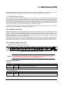
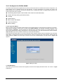
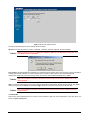
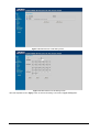
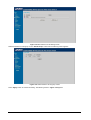
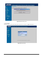
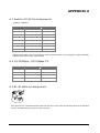
48-10/100Mbps + 4G Ethernet Web Smart Switch FGSW-4840S User’s Manual Trademarks Copyright PLANET Technology Corp. 2004. Contents subject to revision without prior notice. PLANET is a registered trademark of PLANET Technology Corp. All other trademarks belong to their respective owners. Disclaimer PLANET Technology does not warrant that the hardware will work properly in all environments and applications, and makes no warranty and representation, either implied or expressed, with respect to the quality, performance, merchantability, or fitness for a particular purpose. PLANET has made every effort to ensure that this User ’s Manual is accurate; PLANET disclaims liability for any inaccuracies or omissions that may have occurred. Information in this User’s Manual is subject to change without notice and does not represent a commitment on the part of PLANET. PLANET assumes no responsibility for any inaccuracies that may be contained in this User ’s Manual. PLANET makes no commitment to update or keep current the information in this User ’s Manual, and reserves the right to make improvements to this User ’s Manual and/or to the products described in this User ’s Manual, at any time without notice. If you find information in this manual that is incorrect, misleading, or incomplete, we would appreciate your comments and suggestions. FCC Warning This equipment has been tested and found to comply with the limits for a Class A digital device, pursuant to Part 15 of the FCC Rules. These limits are designed to provide reasonable protection against harmful interference when the equipment is operated in a commercial environment. This equipment generates, uses, and can radiate radio frequency energy and, if not installed and used in accordance with the Instruction manual, may cause harmful interference to radio communications. Operation of this equipment in a residential area is likely to cause harmful interference in which case the user will be required to correct the interference at his own expense. CE Mark Warning This is a Class A product. In a domestic environment, this product may cause radio interference, in which case the user may be required to take adequate measures. Revision PLANET Web Smart Gigabit Ethernet Switch User's Manual FOR MODELS: FGSW-4840S Part No.: EM_FGSW4840Sv1 2 TABLE OF CONTENTS 1. INTRODUCTION ........................................................................................... ……………………1 1.1 PACKAGE CONTENTS ...................................................................................................................................................1 1.2 HOW TO USE THIS MANUAL ..........................................................................................................................................1 1.3 PRODUCT FEATURES ...................................................................................................................................................1 1.4 PRODUCT SPECIFICATIONS ...........................................................................................................................................2 2. INSTALLATION ..........................................................................................................................3 2.1 PRODUCT DESCRIPTION ...............................................................................................................................................3 2.1.1 Product Overview...............................................................................................................................................3 2.1.2 FGSW-4840S Front Panel.................................................................................................................................3 2.1.3 LED Indicators ...................................................................................................................................................3 2.1.4 FGSW-4840S Rear Panel .................................................................................................................................4 2.2 INSTALLING A FGSW-4840S........................................................................................................................................4 2.2.1 Desktop Installation ...........................................................................................................................................4 2.2.2 Rack Mounting ...................................................................................................................................................5 3. CONFIGURATION......................................................................................................................6 3.1 PREPARING FOR CONFIGURATION...................................................................................................................................6 3.1.1 Install the Web Switch utility ..............................................................................................................................6 3.1.2 Configure the FGSW-4840S............................................................................................................................18 4. SWITCH OPERATION .............................................................................................................33 4.1 ADDRESS TABLE ........................................................................................................................................................33 4.2 LEARNING .................................................................................................................................................................33 4.3 FORWARDING & FILTERING .........................................................................................................................................33 4.4 STORE-AND-FORWARD...............................................................................................................................................33 4.5 AUTO-NEGOTIATION ...................................................................................................................................................33 5.TROUBLESHOOTING...............................................................................................................34 APPENDIX A ................................................................................................................................35 A.1 SWITCH‘S RJ-45 PIN ASSIGNMENTS ...........................................................................................................................35 A.2 10/100MBPS, 10/100BASE-TX .................................................................................................................................35 A.3 RJ-45 CABLE PIN ASSIGNMENT ...................................................................................................................................35 3 1. INTRODUCTION 1.1 Package Contents Check the contents of your package for following parts: ● Web Smart Gigabit Ethernet Switch x1 ● CD-ROM user's manual x1 ● Quick installation guide x1 ● 19” rack mounting kit x1 ● Power cord x1 ● Rubber feet x 4 If any of these are missing or damaged, please contact your dealer immediately, if possible, retain the carton including the original packing material, and use them against to repack the product in case there is a need to return it to us for repair. 1.2 How to Use This Manual This 48-10/100Mbps+4G Ethernet Web Smart Switch User Manual is structured as follows: § Section 2, Installation It explains the functions of FGSW-4840S and how to physically install the FGSW-4840S. § Section 3, Configuration It contains information about the Smart function of FGSW-4840S. § Section 4, Switch operation It contains specifications of FGSW-4840S. § Section 5, Troubleshooting It contains troubleshooting guide of FGSW-4840S. § Appendix A It contains cable information of FGSW-4840S. In the following section, the term “Switch” means the FGSW-4840S; term of “switch” can be any third part switches. 1.3 Product Features § Complies with IEEE802.3, 10Base-T, IEEE802.3u, 100Base-TX and IEEE802.3ab, 1000Base-T § 48-port 10/100Mbps Ethernet ports § 2 10/100/1000Mbps ports and 2-SFP mini-GBIC interfaces § Features Store-and-Forward mode with wire-speed filtering and forwarding rates § Hardware based 10/100Mbps, half/full duplex and 1000Mbps full duplex mode, flow control and auto-negotiation § IEEE802.3x flow control for full duplex operation and backpressure for half duplex operation § Integrated address look-up engine, support 4K absolute MAC addresses § Remote Web management interface § System log, view trap, firmware upgrade, IP setting through the Web Switch utility § Port-based VLAN, Trunk, QoS support § Supports backup and restore current configuration § Trap function for Switch events § Automatic address learning and address aging § Supports Auto-MDI/MDI-X function 1 § Support CSMA/CD protocol § 100~240VAC, 50~60Hz universal Power input § FCC, CE class A compliant 1.4 Product Specifications Model FGSW-4840S Hardware Specification 10/100Base-TX ports 48 10/100/1000Mbps ports 2 SFP-Mini-GBIC interfaces 2 Switch architecture Store-and-Forward Switch Fabric 17.6Gbps Switch throughput 13Mpps Address Table 4K entries Share data Buffer Flow Control 1536KBytes Back pressure for half duplex, IEEE 802.3x Paus e Frame for full duplex Dimensions (mm) 440 x 200 x 44 mm (1U height) Weight 3kg Power Requirement 100-240V AC, 50-60 Hz Power Consumption 24 watts, 81 BTU Standards Conformance Network Standards IEEE 802.3 (Ethernet), IEEE 802.3u (Fast Ethernet) IEEE 802.3ab (Gigabit Ethernet) IEEE 802.3z (Gigabit Ethernet) IEEE 802.3x (Full-duplex flow control) Operating Temperature 0~50ºC Storage Temperature -40~70ºC Humidity 5% to 90% (Non-condensing) Regulation Compliance FCC Part 15 Class A, CE 2 2. INSTALLATION This section describes the functionalities of FGSW-4840S ’s components and guides how to install it on the desktop or shelf. Basic knowledge of networking is assumed. Please read this chapter completely before continuing. 2.1 Product Description The PLANET FGSW-4840S is a 10/100/1000Mbps Ethernet Switch provides 48 10/100Base-TX ports respectively with 2 10/100/1000Base-T ports and 2-SFP Mimi-GBIC interfaces. With a 17.6Gbps internal switching fabric, the FGSW-4840S can handle extremely large amounts of data in a secure topology linking to a backbone or high capacity servers. The FGSW-4840S has a 4K MAC Address table and provides a 1536KBytes frame buffer. The FGSW-4840S offers wire-speed packet transfer performance without risk of packet loss. The high data throughput of these devices make them ideal for most Gigabit environments, especially network upgrades to a Gigabit environment. The additional Web Switch utility allows access Web interface of FGSW-4840S. Smart function such as per port speed, duplex, flow-control and QoS settings, Trunking , port-based VLAN. 2.1.1 Product Overview PLANET FGSW-4840S is a Web Smart Gigabit Ethernet Switch with 48 Fast Ethernet ports and 2 Gigabit Ethernet ports support 10/100Mbps and 10/100/1000Mbps Auto-Negotiation for optimal speed detection through RJ-45 Category 6, 5 or 5e cables. Also, all the ports support Auto-MDI/MDI-X that can detect the type of connection to any Ethernet device without requiring special straight or crossover cables. The FGSW-4840S also provides 2 SFP Mini-GBIC interfaces for fiber extension to uplink to a server or a network backbone. This products also supports store-and-forward forwarding scheme to ensure low latency and high data integrity, eliminates unnecessary traffic and relieves congestion on critical network paths. With an intelligent address recognition algorithm, FGSW-4840S could recognize up to 4K different MAC address and enables filtering and forwarding at full wire speed. 2.1.2 FGSW-4840S Front Panel Figure 2-1 shows a front panel of FGSW-4840S. Figure 2-1 PLANET FGSW-4840S Front Panel @Note: To press and release the RESET button. The FGSW-4840S will back to the factory default mode. Be sure that you backup the current configuration of FGSW-4840S; else the entire configuration will be erased when pressing the “RESET” button. 2.1.3 LED Indicators System LED Color Function PWR Green Lights to indicate that the Switch has power. SYSTEM Green Lights and blinking to indicate the CPU is working. Per 10/100Mbps port LED LNK/ACT Color Green Function Lit: indicate the link through that port is successfully established. Blink: indicate that the switch is actively sending or receiving data over that port. 3 Per 1000Base-T port LED Color LNK/ACT SPEED Function Lit: indicate the link through that port is successfully established. Blink: indicate that the switch is actively sending or receiving data over that port. Green: indicate that the port is operating at 1000Mbps. Green/orange Orange: indicate that the port is operating at 100Mbps. Green Per SFP-Mini-GBIC port LED Color LNK/ACT Green Function Lit: indicate the link through that port is successfully established. Blink: indicate that the switch is actively sending or receiving data over that port. 2.1.4 FGSW-4840S Rear Panel The rear panel of the Switch indicates an AC inlet power socket, which accepts input power from 100 to 240VAC, 50-60Hz. 100~240V AC 50/60 Hz Figure 2-2 Rear Panel of FGSW-4840S Power Notice: 1. The device is a power-required device, it means, it will not work till it is powered. If your networks should active all the time, please consider using UPS (Uninterrupted Power Supply) for your device. It will prevent you from network data loss or network downtime. 2. In some area, installing a surge suppression device may also help to protect your switch from being damaged by unregulated surge or current to the Switch or the power adapter. 2.2 Installing a FGSW-4840S This section describes how to install your FGSW-4840S Web Smart Gigabit Ethernet Switch and make connections to the switch. Please read the following topics and perform the procedures in the order being presented. PLANET FGSW-4840S Web Smart Gigabit Ethernet Switch do not need software configuration. To install your FGSW-4840S on a desktop or shelf, simply complete the following steps. 2.2.1 Desktop Installation To install an FGSW-4840S on a desktop or shelf, simply complete the following steps: Step1: Attach the rubber feet to the recessed areas on the bottom of the switch. Step2: Place the FGSW-4840S on a desktop or shelf near an AC power source. Step3: Keep enough ventilation space between the Switch and the surrounding objects. @Note: When choosing a location, please keep in mind the environmental restrictions discussed in Chapter 1, Section 4, Specification. Step4: Connect your FGSW-4840S to network devices. A. Connect one end of a standard network cable to the 10/100 or 10/100/1000 RJ-45 ports on the front of the FGSW-4840S B. Connect the other end of the cable to the network devices such as printer servers, workstations or routers …etc. @Note: Connection to the Switch requires UTP Category 5 network cabling with RJ-45 tips. For more information, please see the Cabling Specification in Appendix A. 4 Step5: Supply power to the Switch. A. Connect one end of the power cable to the FGSW-4840S. B. Connect the power plug of the power cable to a standard wall outlet. When the FGSW-4840S receives power, the Power LED should remain solid Green. 2.2.2 Rack Mounting To install the switch in a 19-inch standard rack, follow the instructions described below. Step1: Place your FGSW-4840S on a hard flat surface, with the front panel positioned towards your front side. Step2: Attach a rack-mount bracket to each side of the Switch with supplied screws attached to the package. Figure 2-3 shows how to attach brackets to one side of the Switch. Figure 2-3 Attaching the brackets to the FGSW-4840S Caution: You must use the screws supplied with the mounting brackets. Damage caused to the parts by using incorrect screws would invalidate your warranty. Step3: Secure the brackets tightly. Step4: Follow the same steps to attach the second bracket to the opposite side. Step5: After the brackets are attached to the Switch, use suitable screws to securely attach the brackets to the rack, as shown in Figure 2-4 Figure 2-4 Mounting the Switch in a Rack Step6: Proceed with the steps 4 and steps 5 of session 2.2.1 Desktop Installation to connect the network cabling and supply power to your Switch. 5 3. CONFIGURATION Unlike the unmanaged switch (Dumb switch), FGSW-4840S performs series smart functions that make the Switch operate more effectively. This Chapter will describe the common usage of the Switch ’s Smart Configuration. 3.1 Preparing for configuration When you are ready to configure the smart functions of the Web Smart Gigabit Ethernet Switch. Please install the Web Switch utility and it can easily list the FGSW-4840S in your Ethernet environment. This Web Switch Utility allows assigning an IP address or password change and firmware upgrade for the FGSW-4840S. You can easily configure the FGSW-4840S’s Smart function through the Web browser. Such as per port speed, duplex, flow control, QoS settings, Trunking and port-based VLAN. 3.1.1 Install the Web Switch utility The following install instructions guiding you through the installations of the Web Switch utility. 1. Insert the attached user’s manual CD in the CD-ROM Drive. 2. The CD-ROM drives to initiate auto run program. Once, completed. The screen in Figure 3-1 appears. Figure 3-1 Web Switch Utility location 3. Press the Web Switch Utility and follow the on-screen instructions to install the utility. The install procedures in following screens appear. 6 Figure 3-2 Web Switch Utility install process Figure 3-3 Web Switch Utility install process 7 Figure 3-4 Web Switch Utility install process Figure 3-5 Web Switch Utility install process 8 Figure 3-6 Web Switch Utility install process Figure 3-7 Web Switch Utility install completed 4. After install completed, choose Program Files -> PLANET Web Switch and execute the Web Switch utility. The screen in Figure 3-8 appears. 9 Figure 3-8 Web Switch Utility main screen The Web Switch Utility was divided into four parts, Toolbar function, Discovery List, Monitor List, Device Setting, please refer to the below section for the details instruction. 3.1.1.1 Toolbar function The toolbar in the Web Switch Utility provide four main tabs. File. View. Options. Help. 3.1.1.1.1 File In the “File TAB”, it provides Monitor Save, Monitor Save As, Monitor Load and Exit item. The detail explanation of each item is shown as below: Monitor Save: to save the current setting of the Monitor List as the Default mode, when user access the Web Switch Utility next time, it will load the default setting automatically. Monitor Save As: to save the current setting of the Monitor List in specific filename and file path. Monitor Load: to load the saved setting file of the Monitor List. Exit: to exit the Web Switch Utility. 10 Figure 3-9 Web Switch Utility’s File screen 3.1.1.1.2 View In the “View TAB”, it provides view log and clear log function, this function will help user to view the trap message. The detail explanation of each item is shown as below: View Log: to display the events of the FGSW-4840S. Clear Log: to clear the log of FGSW-4840S. Figure 3-10 Web Switch Utility’s View screen 3.1.1.1.3 Option In the “Option TAB”, it provides Refresh Time function, this function allow user to refresh the monitoring time of Web Switch Utility. The available options are 15 secs, 30 secs, 1 min, 2 min and 5 min . Figure 3-11 Web Switch Utility’s Option screen 11 3.1.1.1.4 Help In the “Help TAB”, it provides “About” function, it display the version of the Web Switch Utility. Figure 3-12 Web Switch Utility’s Help screen 3.1.1.2 Discovery List This function allows user to list the FGSW-4840S in the entire network. By pressing the “Discovery” button, you can list the FGSW-4840S in the discovery list. Double click or press the “Add to monitor list” button to select a device from the Discovery List to the Monitor List. The screen in Figure 3-13 appears. Figure 3-13 Discover list screen 12 The Discovery List contains nine items: MAC Address: display the Switch MAC Address. IP Address: display the current IP address of the Switch. Protocol version: display the version of the Utility protocol. Product Name: display the Switch model name. System Name: display the appointed Switch system name. Location: display where the Switch is located. Trap IP: display the IP address where the Trap to be sent. Subnet Mask: display the Subnet Mask set of Switch. Gateway: display the Gateway set of the Switch. 3.1.1.3 Monitor List All the FGSW-4840S in the Monitor List can be monitored; user can receive the trap and view the status of each Switch. The screen in Figure 3-14 appears. Figure 3-14 Monitor list screen The Monitor List contains nine items: S: display the system symbol of the FGSW-4840S, represent for Switch system is not alive. IP Address: display the current IP address of the Switch. MAC Address: display the Switch MAC Address. 13 Protocol version: display the version of the Utility protocol. Product Name: display the Switch model name. System Name: display the appointed Switch system name. Location: display where the Switch is located. Trap IP: display the IP address where the Trap to be sent. Subnet Mask: display the Subnet Mask set of the Switch. Gateway: display the Gateway set of the Switch. View Trap: The trap function can receive the events that happen from FGSW-4840S in the Monitor List. There is a light indicator behind the “View Trap” button, when the light indicates in green, it means that there is no trap received, and else when it indicates in red, it means that there is new trap received, the screen in Figure 3-15 appears. Figure 3-15 View Trap screen When clicked the “View Trap” button, the latest Trap Information screen will shown and display the trap information including the Symbol, Time, Switch IP and the Event occurred. The screen in Figure 3-16 appears. ! The symbol “ ” represents the trap signal arise, this symbol will disappear after you review and click on the event information. 14 Figure 3-16 Trap information screen @Note: In order to receive Trap information, the FGSW-4840S must configured with Trap IP and Trap Events in Web interface. Please refer to chapter 3.1.2.9 Trap for detail information. Add Item: To add a device to the Monitor List manually, enter the IP Address of the device that want to monitor. Delete Item: To delete the device from the Monitor List. 3.1.1.4 Device Settings This function contains four items to setting the FGSW-4840S . Configuration Setting: this function allows to assign the IP Address, Subnet Mask, Gateway and Set Trap to (Trap IP Address), System name and Location. Select one device in the Discovery list or Monitor List and press this button, then the Configuration Setting screen shown as Figure 3-17, after filling up the data that need to change and fill up the password, press the “Set” button to take effect. Figure 3-17 Configuration setting screen Password Change: this function allows changing the password fill in the password needed in the dialog box and press “Set” button to take effect. The screen in Figure 3-18 appears. Figure 3-18 Password Change screen @Note: Up to 20 characters is allowed for the password. 15 Firmware Upgrade: this function allows new firmware upgrade of FGSW-4840S. The screen in Figure 3-19 appears. Figure 3-19 Firmware Upgrade screen Firmware upgrade Procedure Step 1: Click “Browse” button to select the file where you have just saved in your workstation and ‘Choose file’ dialog box will appear, prompting you to select the file to upgrade the firmware. Step 2: Please input the correct password and click “Start” button to start replacing the latest Firmware revision. The screen in Figure 3-20 & 3-21 appears. Figure 3-20 Firmware Upgrade process screen 16 Figure 3-21 Firmware Upgrade process screen Step 3: After firmware upgrade completed, the Switch will reboot automatically. Then the following screen in Figure 3-22 & 3-23 appears. Figure 3-22 Firmware Upgrade completed screen Figure 3-23 Firmware Upgrade successful screen After Switch power on completed. Then you can start to use the new firmware of FGSW-4840S. Web Access: Double click the device in the Monitor List or select a device in the Monitor List and press this “Web Access” button to access the Web interface of FGSW-4840S. 17 3.1.2 Configure the FGSW-4840S The FGSW-4840S Web Smart Gigabit Ethernet Switch provide Web interface for Switch smart function configuration. The FGSW-4840S can be configured through the Web Browser. A network administrator can manage and monitor the FGSW-4840S from the local LAN. This section indicates how to configure the Switch to enable its smart function. The smart functions are shown as below: ◆ Port Setting (Speed duplex mode/ Disable, Flow Control and Port base QoS) ◆ Virtual LAN Group setting (Port-based VLAN) ◆ Trunking ◆ System Setting ◆ Device status and Statistic ◆ Trap and Password ◆ Backup Setting 3.1.2.1 Login the Switch Before you start configure the FGSW-4840S, please note the FGSW-4840S is configured through an Ethernet connection, make sure the manager PC must be set on same the IP subnet address. For example, the default IP address of the FGSW-4840S is 192.168.0.1, then the manager PC should be set at 192.168.0.x (where x is a number between 2 and 254), and the default subnet mask is 255.255.255.0. Use Internet Explorer 5.0 or above Web browser. Enter IP address http://192.168.0.1 (the factory-default IP address) to access the Web interface. Or through the Web Switch Utility, do not need to remember the IP Address, select the device in the Monitor List of the Web Switch Utility to settle the device through the Web Browser. When the following login screen appears, please enter the default password "admin" and press Login to enter the main screen of FGSW-4840S. The login screen in Figure 3-24 appears. Figure 3-24 Login screen 3.1.2.2 Main Menu After entering the password, the main screen appears, the main screen displays the Switch status. The screen in Figure 3-25 appears. 18 Figure 3-25 Web Main screen 3.1.2.3 Port This function allows displaying each port ’s status. The Link Status in the screen displays the current connection speed and duplex mode; else this function will show “Down” when the port is disconnected. Press the “Refresh” button to renew the screen. The screen in Figure 3-26 appears. Figure 3-26 Port Setting screen Press the port ID to configure each port ’s speed duplex mode and disable, flow control, QoS settings. The screen in Figure 3-27 appears. 19 Figure 3-27 Per Port Setting screen The options and descriptions of Port Settings shown as below: Speed: this function provides six modes —100M Full, 100M Half, 10M Full, 10M Half, Auto and Disable. @Note: When set each port to run at 100M Full, 100M Half, 10M Full, and 10M Half-speed modes. The Auto-MDIX function will disable. Flow Control: this setting determines whether or not the Switch will be handling flow control. Set Flow Control to enable for avoiding data transfer overflow. Or it sets to disable; there is either no flow control or other hardware/software management. When the port is set to forced mode, then the flow control will automatically set to disable. @Note: Due to the hardware restriction. The flow control function cannot across between port 1-24 and port 25-52. QoS: In some ports that need to have a high priority to deal with the data transfer, QoS should be change. The default setting of all port QoS is Normal, set the QoS to High where the ports have a high priority of transfer data. @Note: Due to the hardware restriction. The QoS control function cannot across between port 1-24 and port 25-52. 3.1.2.4 VLAN This function group individual ports into a small “Virtual” network of their own to be independent of the other ports. The screen in Figure 3-28 appears. 20 Figure 3-28 VLAN Setting screen To add a VLAN group, please press “Add Group” button, the new VLAN configuration screen will pop out, you can fill in the description in order to describe this VLAN Group, check on the port to be a member to this VLAN Group. There are two groups for VLAN Setting and only can choose one group in the same time, check on the port to be a member to the Port Group 1 or Port Group 2 then press “Apply” button to execute the setting. The screen in Figure3-29 appears. Figure 3-29 Per VLAN Setting screen Once you want to modify the existence VLAN Group, press the ID parameter, the ID VLAN configuration screen will pop out. The screen in Figure 3-30 & 3-31 appears. 21 Figure 3-30 Edit existence VLAN Setting screen Figure 3-31 Edit existence VLAN Setting screen After edit completed. Press “Apply” button to execute the setting. The screen in Figure 3-32 appears. 22 Figure 3-32 Edit existence VLAN Setting screen Delete the existence VLAN group. Press “Delete Group” button then the following screen appears. Figure 3-33 Delete existence VLAN group screen Press “Apply” button to execute the setting. The following screen in Figure 3-34 appears. 23 Figure 3-34 Delete existence VLAN group screen @Note: The FGSW-4840S supports 26 port-based VLAN groups. Due to the hardware restriction. The port-based VLAN function cannot across between port 1-24 and port 25-52. 3.1.2.5 Trunking This function provide to cascade two Switch devices with a double bandwidth (maximum up to 4000Mbps in full duplex mode). There are seven trunk groups and each group provides four selections for fixed trunk port setting. Group 1~Group 6 provide Fast Ethernet trunk setting (port 1 to port 48), Group 7 for Gigabit Ethernet trunk setting (port 49 and port 50). There are four selections in each trunk group and it shown as follow: Group 1: Selection 1(Disable) Selection 2(port 1, 2) Selection 3(port 1, 2, 3, 4) Selection 4(port 1, 2, 3, 4, 5, 6, 7, 8) Group 2: Selection 1(Disable) Selection 2(port 9, 10) Selection 3(port 9, 10, 11, 12) Selection 4(port 9, 10, 11, 12, 13, 14, 15, 16) Group 3: Selection 1(Disable) Selection 2(port 17, 18) Selection 3(port 17, 18, 19, 20) Selection 4(port 17, 18, 19, 20, 21, 22, 23, 24) Group 4: Selection 1(Disable) Selection 2(port 25, 26) Selection 3(port 25, 26, 27, 28) Selection 4(port 25, 26, 27, 28, 29, 30, 31, 32) Group 5: Selection 1(Disable) Selection 2(port 33, 34) Selection 3(port 33, 34, 35, 36) 24 Selection 4(port 33, 34, 35, 36, 37, 38, 39, 40) Group 6: Selection 1(Disable) Selection 2(port 41, 42) Selection 3(port 41, 42, 43, 44) Selection 4(port 41, 42, 43, 44, 45, 46, 47, 48) Group 7: Selection 1(Disable) Selection 2(port 49, 50) After setup completed. Press “Apply” button to execute the setting. The trunking screen in Figure 3-35 appears. Figure 3-35 Trunking Setting screen @Note: Be sure that the selected trunk port must connect to the Switch under the same VLAN group 25 3.1.2.6 Status Click on the “Status” to present the Switch status on this screen, it display the Switch Status, Port Status, VLAN Status, Trunk Status. Press “Refresh” to renew the posted information. The Status screen in Figure 3-36 appears. Figure 3-36 Status screen 3.1.2.7 Statistics The Statistic screen displays the status of packet count from each port. Press “Refresh” to renew the posted information. The statistics screen in Figure 3-37 appears. Figure 3-37 Statistics screen Press the port ID for detail packet information on each port. Press “Refresh” to renew the posted information. The screen in Figure 3-38 appears. 26 Figure 3-38 Per port Statistics screen 3.1.2.8 System The System Setting includes the System name, Location name, Login Timeout, IP Address, Subnet Mask and Gateway. Through the Web Switch Utility, you can easily recognize the device by using the System Name and the Location Name. The Login Timeout is to set the idle time-out for security issue, when there is no action in running the Web Switch Utility and the time is up, you must re-login to Web Switch Utility before you set the Utility. Fill up the IP Address, Subnet Mask and Gateway for the device. The screen in Figure 3-39 appears. Figure 3-39 System Setting screen 27 3.1.2.9 Trap The Trap function enables the Switch to monitor the Trap through the Web Switch Utility, set the Trap IP Address of the manager workstation where the trap to be sent. After setup completed. Press “Apply” button to execute the setting. The screen in Figure 3-40 appears. Figure 3-40 Trap Setting screen The descriptions of each item is shown as below: System Events: Monitoring the Switch’s trap. The options and explanation are shown as following: Device Bootup: produce a trap when booting up the Switch. Illegal Login: produce a trap when there is a wrong password login, and it will record from which IP login. Fiber Port Events: monitoring the Switch fiber port status. The options and the explanation are shown as following: link up/link down: produce a trap when the fiber link up or link down. Abnormal* Receive Error: produce a trap when Switch fiber port receives error data. Abnormal* Transmit Error: produce a trap when Switch fiber port transmits error data. Twisted Pair Port Events: monitoring the Switch copper port status. The options and explanation are shown as following: Abnormal* Receive Error: produce a trap when Switch copper port receives error data. Abnormal* Transmit Error: produce a trap when Switch copper port transmits error data. @Note: Abnormal*: 50-error packet count within 10 seconds. 28 3.1.2.10 Password Setting This function provides administrator to secure FGSW-4840S. After setup completed. Press “Apply” button to execute the setting. The screen in Figure 3-41 appears. Figure 3-41 Password Setting screen @Note: Up to 20 characters is allowed for the password. After change the default password, if you forget the password. Please press and release the “Reset” button in the front panel of FGSW-4840S, the current setting includes VLAN, will be lost and the FGSW-4840S will restore to the default mode. 3.1.2.11 Backup Setting This function allows backup and restore the current configuration of FGSW-4840S. The screen in Figure 3-42 appears. Figure 3-42 Backup Setting screen 29 Press the “Backup” button to save the current configuration in manager workstation. The following screens in Figure 3-43& 3-44 & 3-45 appear. Figure 3-43 Backup Setting screen Figure 3-44 Backup Setting screen 30 Figure 3-45 Backup Setting screen To restore a current configuration file to the FGSW-4840S, please specify the backup file and press “Restore” button to continue, after restore completed, the FGSW-4840S will reboot for the previous configuration. The screen in Figure 3-46 & 3-47 appears. Figure 3-46 Restore Setting screen Figure 3-47 Restore Setting screen 3.1.2.12 Reset Setting The Factory Reset button can reset the FGSW-4840S back to the factory default mode. Be aware that the entire configuration will be reset; the IP address of the FGSW-4840S will be set to default setting 192.168.0.1. The screen in Figure 3-48 appears. 31 Figure 3-48 Reset Setting screen 3.1.2.13 Logout Press this function; the web interface will go back to login screen. The screen in Figure 3-49 appears. Figure 3-49 Logout screen 32 4. SWITCH OPERATION 4.1 Address Table The Switch is implemented with an address table. This address table composed of many entries. Each entry is used to store the address information of some node in network, including MAC address, port no, etc. This information comes from the learning process of Ethernet Switch. 4.2 Learning When one packet comes in from any port, the Switch will record the source address, port no. And the other related information in address table. This information will be used to decide either forwarding or filtering for future packets. 4.3 Forwarding & Filtering When one packet comes from some port of the Ethernet Switching, it will also check the destination address besides the source address learning. The Ethernet Switching will lookup the address-table for the destination address. If not found, this packet will be forwarded to all the other ports except the port, which this packet comes in. And these ports will transmit this packet to the network it connected. If found, and the destination address is located at different port from this packet comes in, the Ethernet Switching will forward this packet to the port where this destination address is located according to the information from address table. But, if the destination address is located at the same port with this packet comes in, then this packet will be filtered. Thereby increasing the network throughput and availability. 4.4 Store-and-Forward Store-and-Forward is one type of packet-forwarding techniques. A Store-and-Forward Ethernet Switching stores the incoming frame in an internal buffer, do the complete error checking before transmission. Therefore, no error packets occurrence, it is the best choice when a network needs efficiency and stability. The Ethernet Switch scans the destination address from the packet-header, searches the routing table provided for the incoming port and forwards the packet, only if required. The fast forwarding makes the switch attractive for connecting servers directly to the network, thereby increasing throughput and availability. However, the switch is most commonly used to segment existing hubs, which nearly always improves overall performance. An Ethernet Switching can be easily configured in any Ethernet network environment to significantly boost bandwidth using conventional cabling and adapters. Due to the learning function of the Ethernet switching, the source address and corresponding port number of each incoming and outgoing packet are stored in a routing table. This information is subsequently used to filter packets whose destination address is on the same segment as the source address. This confines network traffic to its respective domain, reducing the overall load on the network. The Switch performs "Store and forward" therefore, no error packets occur. More reliably, it reduces the re-transmission rate. No packet loss will occur. 4.5 Auto-Negotiation The STP ports on the Switch have built-in “Auto-negotiation”. This technology automatically sets the best possible bandwidth when a connection is established with another network device (usually at Power On or Reset). This is done by detect the modes and speeds at the second of both device is connected and capable of, both 10Base-T and 100Base-TX devices can connect with the port in either Half- or Full-Duplex mode. 1000Base-T can be only connected in Full-duplex mode. 33 5.TROUBLESHOOTING This chapter contains information to help you solve problems. If the Switch is not functioning properly, make sure the Ethernet Switch was set up according to instructions in this manual. The Link LED is not lit Solution: Check the cable connection and its quality. Some stations cannot talk to other stations located on the other port Solution: Please check the VLAN, port trunking function that may introduce this kind of problem. The address table may contain older information than of the address table of that node. Please power down to refresh the address information. Performance is bad Solution: Check the full duplex status of the partner Switch or device. The partner switch is run at full duplex and the Switch runs at Auto-Negotiation (half-duplex mode), then the performance will be poor. Why the Switch doesn’t connect to the network Solution: Check the LNK/ACT LED on the Switch Try another port on the Switch Make sure the cable is installed properly Make sure the cable is the right type Turn off the power. After a while, turn on power again Why the LNK/ACT LED of SFP-Mini-GBIC interfaces is not lit? Solution: Check the fiber connection Assure use the correct fiber cable for multi-mode and single-mode Check the port setting of this Switch 34 APPENDIX A A.1 Switch‘s RJ-45 Pin Assignments 1000Mbps, 1000Base T Contact MDI MDI-X 1 BI_DA+ BI_DB+ 2 BI_DA- BI_DB- 3 BI_DB+ BI_DA+ 4 BI_DC+ BI_DD+ 5 BI_DC- BI_DD- 6 BI_DB- BI_DA- 7 BI_DD+ BI_DC+ 8 BI_DD- BI_DC- Implicit implementation of the crossover function within a twisted-pair cable, or at a wiring panel, while not expressly forbidden, is beyond the scope of this standard. A.2 10/100Mbps, 10/100Base-TX Contact MDI MDI-X 1 1 3 2 2 6 3 3 1 6 6 2 A.3 RJ-45 cable pin assignment 6 321 6 321 6 3 21 There are 8 wires on a standard UTP/STP cable and each wire is color-coded. The following shows the pin allocation and color of straight cable and crossover cable connection: 35 Figure A-1: Straight-Through and Crossover Cable Please make sure your connected cables are with same pin assignment and color as above picture before deploying the cables into your network. EM_FGSW4840Sv1 36