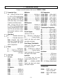
1
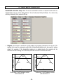
MT SERIES
TRANSMITTERS
ANALOG INPUT
4-20 MA OUTPUT & RS232 / RS485 I/O
USER MANUAL
MICRON METERS
Tel: (435) 251-8106 •
Fax: (435) 251-8107 •
Website: www.micronmeters.com
1. ORDERING GUIDE
Configure a model number in this format: LT20DCV1, CBL04
Transmitter Type
RMS Volts
RTD Temperature
LT......4-20 mA, 0-20 mA, 0-10V,
or -10V to +10V isolated analog
output, isolated RS232/RS485
serial data output, two 120 mA
solid state relays, and isolated
transducer excitation output.
RMV1 ...................... 200.00 mV
RMV2 ......................... 2.0000 V
RMV3 ......................... 20.000 V
RMV4 ......................... 200.00 V
RMV5 ........................... 600.0 V
LTE.... 4-20’mA, 0-20 mA, 0-10V
or -10V to +10V isolated analog
output, isolated Ethernet output,
two 120 mA solid state relays,
and isolated transducer excitation output.
RMA1 ...................... 2.0000 mA
RMA2 ...................... 20.000 mA
RMA3 ...................... 200.00 mA
RMA4 ........................... 5.000 A
Pt100, P385C ..... -202 to 850°C
Pt100, P385F ... -331 to 1562°F
Pt100, P392C .... .-202 to 850°C
Pt100, P392F ... -331 to 1562°F
Ni120, 672C ........ .-80 to 260°C
Ni120, 672F ....... -112 to 500°F
Cu10, 427C.......... .-97 to 260°C
Cu10, 427F ......... -143 to 500°F
RMS Amperes
Thermocouple Temperature
JC ....................... -210 to 760°C
JF...................... -347 to 1400°F
Process Signals
KC ..................... -244 to 1372°C
4-20 mA, 0-10V, etc.
KF ..................... -408 to 2501°F
Main Board
2............... Standard main board P…...4-20 mA in = 4-20 mA out TC ....................... -257 to 400°C
4...............Extended main board P1…………….Custom Scaling TF ....................... -430 to 752°F
EC ..................... -240 to 1000°C
Note: Extended main board Specify min input and output, EF ..................... -400 to 1830°F
adds rate of change and custom max input and output.
NC ..................... -245 to 1300°C
curve linearization. Not applic- Strain Gauge, Potentiometer
NF .................... .-410 to 2370°F
able to temperature.
4-wire ratio. Full scale ranges SC ....................... -46 to 1768°C
SF ....................... -51 to 3214°F
Power
from 200 mV to 20V.
0.............................. 85-264 Vac SG ....... 0-200 mV in = 4-20 mA RC ...................... .-45 to 1768°C
1.......... 12-32 Vac or 10-48 Vdc SG1 .................. Custom Scaling RF ....................... -49 to 3213°F
2................ Power over Ethernet Specify min input & min output, Resistance
(LTE only) max input & max output.
R1 ............................ 0-20 ohms
Input Type
R2 .......................... 0-200 ohms
Load Cells
R3…………...…. .... 0-2 kohms
DC Volts
4- or 6-wire ratio. Full scale
R4 .......................... 0-20 kohms
DCV1 ........................200.00 mV ranges from 20 to 500 mV.
R5 ........................ 0-200 kohms
DCV2 ...........................2.0000 V
WM1........... -99,999 to +99,999 R6 ...... 0-2 Mohms (fixed range)
DCV3 ...........................20.000 V
DCV4 ...........................200.00 V Specify min input and output,
DCV5 .............................600.0 V max input & output.
DC Amperes
ACCESSORIES
DCA1 ........................2.0000 mA
DCA2 ........................ 20.000 mA
DCA3 ........................200.00 mA
DCA4 ............................. 5.000 A
CBL04 .......RS232 cable, transmitter to computer
CBL02 .......USB to DB9 adapter
cable
-2-
2. TABLE OF CONTENTS
1.
ORDERING GUIDE ............................................................................................................ 2
2.
TABLE OF CONTENTS ....................................................................................................... 3
3.
PRODUCT OVERVIEW ....................................................................................................... 4
4.
RECEIVING & UNPACKING YOUR TRANSMITTER ........................................................... 5
5.
SAFETY CONSIDERATIONS .............................................................................................. 5
6.
TRANSMITTER FIELD WIRING ......................................................................................... 6
7.
PROGRAMMING YOUR TRANSMITTER............................................................................ 8
8.
OPENING YOUR TRANSMITTER CASE ............................................................................. 17
9.
DC SIGNAL CONDITIONER BOARD................................................................................... 17
10.
AC SIGNAL CONDITIONER BOARD .................................................................................. 19
11.
LOAD CELL & MICROVOLT SIGNAL CONDITIONER BOARD ............................................ 21
12.
THERMOCOUPLE SIGNAL CONDITIONER BOARD .......................................................... 23
13.
RTD & OHMS SIGNAL CONDITIONER BOARD ................................................................. 25
14.
MAIN BOARD JUMPER SETTINGS ................................................................................... 27
15.
DUAL RELAY OPERATION ............................................................................................... 28
16.
INPUT SIGNAL FILTERING................................................................................................ 31
17.
TRANSMITTER CALIBRATION .......................................................................................... 32
18.
CUSTOM CURVE LINEARIZATION .................................................................................... 33
19.
MODBUS PROTOCOL TRANSMITTER COMMUNICATIONS .............................................. 34
20.
CUSTOM ASCII PROTOCOL TRANSMITTER COMMUNICATIONS .................................... 39
21.
LT SERIES ANALOG INPUT TRANSMITTER SPECIFICATIONS ......................................... 44
22.
WARRANTY ...................................................................................................................... 48
-3-
3. PRODUCT OVERVIEW
This manual covers LT Series DIN rail transmitters with isolated analog and RS232/RS485 outputs,
dual relays, and an analog input signal conditioner. A separate manual covers LTE Series DIN rail
transmitters with isolated 4-20 mA and Ethernet outputs, dual relays, and an analog input signal
conditioner.
LT Series transmitters duplicate the signal conditioning and signal processing features of their
1/8 DIN panel-mounted digital panel meter counterparts for exceptional accuracy at high read rate.
A wide range of analog signal sources are accommodated by five analog signal conditioners:
• DC input for volts, amps, process signals (e.g., 4-20 mA), and strain gauges. Most sensitive
full scale input range of 200 mV. Built-in 5A current shunt.
• AC rms input for volts and amps. Can be AC or DC coupled. Built-in 5A current shunt.
• Load cell or microvolt input with selectable full scale input ranges from 20 mV to 500 mV.
• Thermocouple temperature input for seven thermocouple types.
• RTD temperature or Ohms input for Pt100, Ni120 or Cu10 RTDs, or 20Ω-200 kΩ resistance.
A 4-20 mA, 0-20 mA, 0-10V, or -10V to +10V isolated analog output is standard. This output is
generated by an ultra-linear 16-bit digital-to-analog converter which tracks an internal linearized
digital reading.
Isolated serial communications are standard. The transmitter serial port is default jumpered for
RS232 or full-duplex RS485 (same jumper settings). Half-duplex RS485 is also selectable either
via internal or external jumpers. Three serial protocols are software selectable: Modbus RTU,
Modbus ASCII and Custom ASCII. Modbus allows devices by different manufacturers to be
addressed on the same data line. The simpler Custom ASCII protocol is recommended when there
are no devices by other manufacturers on the data line.
An isolated transducer excitation output is standard, in DC, process and load cell input models.
Three output levels are jumper selectable: 5V at 100 mA, 10V at 120 mA, or 24V at 50 mA. The
factory default setting is 10V and can power up to four 350 ohm load cells in parallel.
Two isolated solid state relays are standard. These are rated 120 mA at 140 Vac or 180 Vdc.
Isolation to 250V rms is provided for power, signal input, analog output, relay outputs, and communications. Isolation adds safety and avoids possible ground loops. The transducer excitation
output is isolated to ±50V from signal ground.
Internal jumpers are used to select the signal range, analog output type, communication type, and
excitation level. The transmitter configuration is specified by the model number on the transmitter
label. A user can reconfigure the transmitter by opening the case and moving jumpers.
Transmitter scaling is via serial connection to a PC using MS Windows based Instrument Setup
Software, which can be downloaded at no charge. The required transmitter-to-PC interface cable
is available for purchase.
-4-
4. RECEIVING & UNPACKING YOUR TRANSMITTER
Your transmitter was carefully tested and inspected prior to shipment. Should the transmitter be
damaged in shipment, notify the freight carrier immediately. In the event the transmitter is not
configured as ordered or is inoperable, return it to the place of purchase for repair or replacement.
Please include a detailed description of the problem.
5. SAFETY CONSIDERATIONS
Warning: Use of this transmitter in a manner other than specified may impair the protection
of the device and subject the user to a hazard. Do not attempt to operate if the unit shows visible
damage.
Cautions:
• This unit may be powered from 85-264 Vac or with the worldwide voltage power supply
option, or from 12-32 Vac or 10-48 Vdc with the low voltage power supply option. Verify that
the proper power option is installed for the power to be used.
• The 85-264 Vac power connector (P1 Pins 1-3) is colored Green to differentiate it from other
input and output connectors. The 12-32 Vac or 10-48 Vdc power connector is colored Black.
This transmitter has no power switch. It will be in operation as soon as power is applied.
• To avoid dangers of electrocution and/or short circuit, do not attempt to open the case while
the unit is under power.
• To prevent an electrical or fire hazard, do not expose the transmitter to excessive moisture.
Do not operate the transmitter in the presence of flammable gases or fumes, as such an
environment constitutes an explosion hazard.
Symbols applicable to this product:
Caution (refer to accompanying documents)
Earth (ground) terminal.
Caution, risk of electric shock.
Both direct and alternating current.
Equipment protected throughout by double
insulation or reinforced insulation.
CE Mark. Indicates that product meets
EU safety, health and environmental
requirements.
ETL Mark. Indicates that product
conforms to UL Std. 61010-1 and is
certified to CAN/USA Std. C22.2 No.
61010-1
4006497
Operating environment:
Transmitter Class II (double insulated) equipment designed for use in Pollution degree 2.
-5-
6. TRANSMITTER FIELD WIRING
-6-
P6 - SIGNAL INPUT DETAIL
DC & Externally Powered Process
Excitation return
+ Excitation
- Signal input
+ Signal input
1
2
3
4
Load Cell
Excitation return
- Sense
- Signal
+ Signal
+ Excitation
+ Sense
-DC
+DC
2-Wire Process Transmitter
Excitation return
+ Excitation
- Signal input
+ Signal input
1
2
3
4
1
2
3
4
5
6
For 4-wire load cell connection, jumper
Pin1 to Pin 2, and Pin 5 to Pin 6.
+
-
RTD or Resistance - 2 Wire
Strain Gauge
Excitation return
+ Excitation
- Signal input
+ Signal input
Excitation return
+ Excitation
- Signal input
+ Signal input
1
2
3
4
1
2
3
4
RTD or Resistance - 3 Wire
AC & AC+DC True RMS
Voltage Signal In
NC
Signal Return
Current or Low
Voltage Signal In
1
2
3
4
2, 20, 200, 600V
AC neutral
2, 20, 200 mA
5A, 0.2VA
Thermocouple
NC
NC
- Signal input
+ Signal input
1
2
3
4
Excitation return
+ Excitation
- Signal input
+ Signal input
1
2
3
4
RTD or Resistance - 4 Wire
Excitation return
+ Excitation
- Signal input
+ Signal input
1
2
3
4
MOUNTING FOR COOLING
P4 - ANALOG OUTPUT DETAIL
Driving a Load with 4-20 mA
Analog return 1
4-20 mA output 2
500 Ohms max
Driving a Load with 0-10V
Analog GND 1
0-10V output 2
5 kOhms min
AL 1
AL 1
AL 1
AL 1
AL 1
AL 1
AL 1
AL 2
AL 2
AL 2
AL 2
AL 2
AL 2
AL 2
RESET
RESET
RESET
RESET
RESET
RESET
RESET
POWER
POWER
POWER
POWER
POWER
POWER
POWER
Mount transmitters with ventilation holes at top
and bottom. Leave minimum of 6 mm (1/4")
between transmitters, or force air with a fan.
-7-
7. PROGRAMMING YOUR TRANSMITTER
Our transmitters are easily programmed using a PC and Instrument Setup (IS) Software, which
provides a graphical user interface. The software allows uploading, editing, downloading and
saving of setup data, execution of commands under computer control, listing, plotting and
graphing of data, and computer prompted calibration.
USING INSTRUMENT SETUP SOFTWARE
RS232 cable with rear view of DB9
connector to PC
Use a 3-wire RS232 cable (P/N CBL04) to connect your transmitter to the COM port of your PC.
Download the file ISx_x_x.exe from our website and double-click on the file name. Click on
“Install Instrument Setup Software” and follow the prompts. To launch IS software, press on
Start => Programs => IS2 => Instrument Setup or on the desktop shortcut that you may have
created. Following a brief splash screen, the Communications Setup screen below will appear.
In the Communications Setup screen, select the “Custom ASCII” as the protocol, as this is the
factory default setting. Select “Transmitter LT” as the Device Type and RS232 the Communications Type. This will take you to the Establish Communications screen.
-8-
In the Establish Communications screen, select your Com Port and 9600 and the Baud Rate.
You will be able to change your protocol and baud rate later under the Communication setup
tab. Click on Establish, and the two fields at the bottom of the screen should turn green. Click
on the Main Menu button.
From the Main Menu, click on DPM => Get Setup to retrieve (or get) the existing setup data
from your DPM transmitter. Click on View => Setup to bring up screens which allow you to
easily edit the setup file using pull-down menus and other selection tools. You can download
(or put) your edited file into the transmitter by clicking on DPM => Put Setup. You can save
your setup file to disk by clicking on File => Save Setup and retrieve a previously saved file from
disk by click on File => Open.
The best way to learn IS software is to experiment with it.
For context-sensitive help for any data entry field under any tab, select that field and press the
F1 key.
-9-
To get to the Input+Display tab, click on DPM => Get Setup to retrieve the current setup
information from your DPM transmitter, then on View => Setup. Use the Input+Display screen
to set up Signal Input, Display, and Control Inputs. The software reads the signal conditioner
type, but not the range, which is set by jumpers. The “50/60 Hz Line Freq” selection is used to
optimize filtering for 50 or 60 Hz electrical noise.
Clicking on the Control Inputs field opens a pull-down menu which allows selection of the
roles of Control Input 1, Control Input 2, and simultaneous Control Inputs 1 and 2. For
example, with a DC signal conditioner and the highlighted selection, grounding Control Input 1
places the transmitter on Hold, grounding Control Input 2 causes the Peak reading to be
transmitted, and grounding both Control Inputs 1 and 2 causes a Function Reset, which resets
Peak, Valley and latched alarms. Note that the roles of the Control Inputs vary with the type of
signal conditioner. Only the applicable roles will be displayed.
- 10 -
Click on the Scaling tab to scale your transmitter. You will be given the choice of three scaling
methods for inputs other than temperature: 1) Scale and Offset method, 2) Coordinates of 2
points method where (Low In, Low Read) and (High In, High Read) data points are entered
numerically, and 3) Reading Coordinates of 2 points method, which uses actual readings.
Click on the Filter tab to set to set up filtering for your readings. The filter time constant can be
automatic, be specified in seconds, or be turned off. The adaptive threshold modifies the time
constant in response to noise. A low adaptive threshold is recommended for normal low noise.
A high adaptive threshold is recommended for high noise environments.
- 11 -
Click on the Relay Alarms tab to set up your transmitter’s two solid state relays, which are
standard. For detailed help on any data entry field under, select that field and press the F1 key.
Click on the Communication tab to view the communication parameters that you used to
establish default communications with your transmitter. You can reselect Baud Rate, Device
Address, Serial Protocol, and Full/Half Duplex, even though you may have selected different
values to establish initial communications with your PC.
- 12 -
Click on the Analog Out tab to scale your analog output, which is standard. Under Range,
select 0-20 mA current, 4-20 mA current, 0-10V voltage, or -10V to +10V voltage. Type in your
Lo Range Reading and Hi Range reading. These will create the two endpoints of your analog
output range.
For detailed help on any data entry field, select that field and press the F1 key.
- 13 -
ADDITIONAL INSTRUMENT SETUP PROGRAM FEATURES
• The Commands pull-down menu allows you to execute certain functions by using your
computer mouse. This menu will be grayed out unless a Get Setup has been executed.
• The Readings pull-down menu provides three formats to display input data on your PC
monitor. Use the Pause and Continue buttons to control the timing of data collection, then
press Print for a hardcopy on your PC printer.
- List presents the latest internal readings in a 20-row by 10-column table. Press Pause at any
time to freeze the display. Press Print for a hardcopy.
- Plot generates a plot of internal readings vs. time in seconds. It effectively turns the
transmitter-PC combination into a printing digital oscilloscope.
- Graph generates a histogram, where the horizontal axis is the internal reading, and the
vertical axis is the number of occurrences of readings. The display continually resizes itself
as the number of readings increases.
Plot
- 14 -
Graph
• The Jumpers pull-down menu shows jumper positions for the selected signal conditioner
boards and the main board, duplicating information in this manual.
- 15 -
8. OPENING YOUR TRANSMITTER CASE
WHEN TO CHANGE JUMPERS
Your transmitter case does not need to be opened if jumpers have already been set by your
distributor. Otherwise you will need to open the case and either set jumpers or verify that the
factory default jumpers positions will meet your needs. Note that while Instrument Setup
Software senses the circuit board type, it does not sense jumper settings, and the corresponding information has to be entered manually. Jumpers are used for the following:
1) On the signal conditioner board to set the signal type (e.g., voltage or current) and the
range. For details, please see the next five sections of this manual. Note that all ranges of
all signal conditioner boards are factory calibrated, with calibration factors stored in
EPROM on the board.
2) On the main board to set the serial communication signal (RS232 or RS485), termination
resistor for long cable runs, analog output signal (current or voltage), and sensor excitation output (5V, 10V or 24V). Default factory settings are current output, RS232, no
termination resistor, and 10V excitation.
HOW TO OPEN & CLOSE THE CASE
The two clamshell halves of the case are held together with a bolt and a nut at each of the four
corners. Use a Phillips screwdriver to remove the four bolts. The nut will then drop off, and the
clamshell halves will separate. When closing the case, make sure that the ventilation grills are
properly aligned.
Caution: The nuts at each corner are not captive and are black. Take precautions
so that the nuts do not get lost.
- 16 -
9. DC SIGNAL CONDITIONER BOARD (DC, PROCESS, STRAIN)
The DC volts, amps, process and strain transmitters utilize the DC signal conditioner board,
which needs to be configured via jumpers for the desired voltage or current range. All signal
ranges are factory calibrated with calibration factors stored in EEPROM on the signal conditioner board. Instrument Setup Software recognizes the board and brings up the appropriate
menu items for it; however, it does not recognize the jumper settings. Ranges also have to be
selected manually. The excitation output can be set to 5V @ 100 mA, 10V @ 120 mA, or 24V @
50 mA via main board jumper settings. Please see Section 14 of this manual.
Board Revisions Q and R
Voltage Ranges
Jumpers
FS Input
E1
E2
E3
±200.00 mV
±2.0000 V
±20.000 V
±200.00 V
±300V (UL)
±600V (not ETL)
A
A
B
B
B
B
f
f
h
h
g
g
b
a
b
a
a
a
B
E1
A
h
b
Current Ranges
E3
Jumpers
a
E2 g
b
a
FS Input
E1
E2
E3
±2.0000 mA
±20.000 mA
±200.00 mA
±5.000 A
A
A
A
A
e, g
d, g
c, g
a, b, g
b
b
b
b
f
c
e
d
1. Use 5 mm (0.2") jumpers for locations E1 designated by a capital letter.
2. Use 2.5 mm (0.1") jumpers for locations E2 and E3 designated by a lower case letter.
3. Store spare jumpers on an unused jumper post not associated with a capital letter.
For DC voltage and current transmitters, a scale factor of 1 and an offset of 0 are used for
readings in volts or amperes. Decimal point selection is independent of the transmitted units.
For example, 20.000 mA or 20000 µA are both be transmitted as 20000 counts.
For process & strain transmitters, three scaling methods can be selected in Instrument Setup
Software: 1) Scale and offset, 2) Coordinates of 2 points, and 3) Reading coordinates of 2
points, which uses actual signals. Only menu items applicable to the selected method are
presented. Note that full-scale ranges are ±20000 counts. For resolution purposes, the 300V
and 600V ranges are 2000V (100 mV/count), and the 5A range is 20A (1 mA/count).
- 17 -
Example: Transmit the digital reading in amps and as 4-20 mA from a 500-100 current shunt
Application: Use a 500-100 (500A, 100 mV) current shunt. Digitally transmit the DC current
reading in amps with 0.1A resolution. Also transmit a 4-20 mA signal corresponding to 0-200A.
Solution:
• Jumper signal conditioner for ±200.00 mV range.
• Under “Input+Display” tab, set “Option Board” to DC, Mode to DC V, Range to 0.2V,
“Decimal Point” to dddd.d, and “50/60 Hz Line Freq” to 60 Hz to reject 60 Hz noise.
• Under Scaling tab, if Coordinates is selected, set “High In” to 0.1V and “High Read” to
500.0A. For this application, Coordinates is the easiest, most intuitive scaling method.
• Under Scaling tab, if “Scale, Offset” method is selected, set Scale to 0.5. The reason is that
a 200 mV full-scale input corresponds to 20,000 input counts, where each input count is
10 µV (as for the 200 mV scale of a 4-digit meter). These 20,000 input counts need to
correspond to 10,000 output counts, where each output count is 0.1A.
• Under “Analog Out” tab, set Range to “4-20 mA current”, “Lo Range Reading” to 0.0A, and
“Hi Range Reading” to 200.0A.
- 18 -
10. AC RMS SIGNAL CONDITIONER BOARD
Five RMS voltage and four RMS current ranges are jumper selectable, as is AC or DC coupling. All
signal ranges are factory calibrated with calibration factors stored in EEPROM on the signal conditioner board. Instrument Setup Software recognizes the board and brings up the appropriate menu
items for it; however, it does not recognize the jumper settings. Ranges also have to be entered
manually.
Board Revision S
Voltage Ranges
200.00 mV
2.0000 V
20.000 V
200.00 V
600.0 V
Current Ranges
2.0000 mA
20.000 mA
200.00 mA
5.000 A
Signal Coupling
AC + DC
AC only
Jumpers
j
c, g, h
c, i
c, k
c, m
Jumpers
m
l, k
b, m
a, m
c, d, e, m
k
l
j
i
h
g
f
e
d
c
b
a
Jumpers
f
none
The flexible noise shield may be removed for
jumper setting, but must then be reinstalled.
1. Use 2.5 mm (0.1") jumpers.
2. Store spare jumpers on an unused jumper post.
3. OK to remove the plug-in shield for jumper setting, but reinstall before closing the case.
To minimize noise pickup, the input signal wiring should utilize a shielded twisted pair, and the
shield should be connected to signal low at the rms board, as illustrated below. If signal low is
close to earth ground, such as within 2V, signal low can further be connected to earth ground.
Sig High
Sig Low
Signal Source
RMS
Board
Shield around twisted pair
Earth Ground
Shielding for AC noise reduction
- 19 -
Example: Transmit the digital reading in amps and as 4-20 mA from an AC current transformer
Application: Use a 200:5 (200A in, 5A out) AC current transformer. Digitally transmit the AC
current reading in amps with 0.1A resolution. Also transmit a 4-20 mA signal corresponding to
0-100A.
Solution:
• Jumper signal conditioner for 5.000 A current range and AC coupling.
• Under “Input+Display” tab, set “Option Board” to True RMS, Mode to RMS A, Range to
5.0A, “Decimal Point” to dddd.d, and “50/60 Hz Line Freq” to 60 Hz to reject 60 Hz noise.
• Under Scaling tab, if Coordinates is selected, set “High In” to 5.000A and “High Read” to
200.0A. For this application, Coordinates is the easiest, most intuitive scaling method.
• Under Scaling tab, if “Scale, Offset” method is selected, set Scale to 0.4. The reason is that
a 5A full-scale input corresponds to 5,000 input counts, where each input count is
1 mA (as for the 5A scale of a 4-digit meter). These 5,000 input counts need to correspond
to 2,000 output counts, where each output count is 0.1A.
• Under “Analog Out” tab, set Range to “4-20 mA current”, “Lo Range Reading” to 0.0A, and
“Hi Range Reading” to 100.0A.
- 20 -
11. LOAD CELL & MICROVOLT SIGNAL CONDITIONER BOARD
The load cell signal conditioner board offers sensitivity to ±20 mV full-scale and 4 or 6-wire
load cell connection. This board needs to be configured via jumpers for the desired full-scale
voltage range. All ranges are factory calibrated with calibration factors stored in EEPROM.
Instrument Setup Software recognizes the board and will bring up the appropriate menu items
for it; however, it does not recognize the jumper settings. The ranges also have to be selected
in Instrument Setup software. The excitation output can be set to 5V @ 100 mA, 10V @ 120
mA, or 24V @ 50 mA via main board jumper settings. Please see Section 14 of this manual.
Operation is ratiometric, with automatic compensation for changes in excitation voltage.
For DC microvolt applications, a scale factor of 1 and an offset of 0 are used for direct readings in microvolts or millivolts. Decimal point selection does not affect the displayed digits. For
example, 20 mV can be transmitted as 20.000 mV or 20000 µV. The decimal point is set
separately.
For load cell applications, three scaling methods can be selected in Instrument Setup
Software: 1) Scale and offset, 2) Coordinates of 2 points, and 3) Reading coordinates of 2
points, which uses actual signals. Only menu items applicable to the selected scaling method
will be presented.
Load Cell & Microvolt Ranges
FS Input
Jumpers
FS Counts
±20.000 mV
±50.000 mV
±100.00 mV
±250.00 mV
±500.00 mV
e
a
b
c
d
±20000
±50000
±10000
±25000
±50000
1. Use 2.5 mm (0.1") jumpers.
2. Store spare jumpers on an unused jumper post.
- 21 -
Example: Transmit weight in decimal tons and as 4-20 mA with overweight alarming
Application: Digitally transmit weight in metric tons with 3 decimal places using a 3 mV/V load
cell. Also output weight from 0 to 5.000 tons as a 0-10V signal. Apply 10V excitation. At a load
of 5.000 tons, the load cell output will be 30 mV. Alarm weight over 4.000 tons, but wait for 8
readings over this limit (or 15 msec) so as not to alarm on a noise spike.
Solution:
• Jumper signal conditioner for 50.000 mV range. Set power supply to 10V excitation.
• Under “Input+Display” tab, set Mode to Strain, range to 50.0mV, decimal point to 3 places,
and “50/60 Hz Line Freq” to 60 Hz to reject 60 Hz noise.
• Under Scaling tab, if “Scale, Offset” method is selected, set Scale to 0.16667. The reason is
that we want 30000 input counts to correspond to 5000 output counts.
• Under Scaling tab, if Coordinates is selected, set “High In” to 30.000 mV and “High Read”
to 5.000 tons.
• Under “Relay Alarms” tab, enter 4.000 tons for Setpoint 1 and 8 readings to alarm.
• Under “Analog Out” tab, set Range to “0-10V Voltage”, “Lo Range Reading” to 0.000 tons
and “Hi Range Reading” to 5.000 tons.
- 22 -
12. THERMOCOUPLE SIGNAL CONDITIONER BOARD
The thermocouple signal conditioner board can be configured via jumpers for 7 thermocouple types, each in a single range: J, K, T, E, N, S, R. Instrument Setup Software
recognizes the board and will bring up the appropriate menu items for it; however, it does
not recognize jumper settings, so the thermocouple type also has to be selected in
Instrument Setup Software. A large number of additional items are selectable in Instrument
Setup Software. For help with any item, highlight that item and press the F1 key. Note that
Decimal Point choices are offered for 1°, 0.1° or 0.01° resolution. The 0.01° choice is not
recommended for thermocouples. Offset adjustment is available under the Scaling tab and
is normally set to 0000.0. If °C is selected, entering an offset of 0273.2 will change the
display to Kelvin. If °F is selected, entering an offset of 0459.7 will change the display to
Rankin.
PNP transistor
Board Revision A
Thermocouple Type
J, K, E, N
T, R, S
Open T/C Indication
Upscale
Downscale
J5-X
E4 Jumper
none
j
J5-Y
E3 Jumper
E3
h
i
h
i
1. Use 2.5 mm (0.1") jumpers.
2. Store spare jumpers on an unused jumper post.
- 23 -
j
E4
1
2
3
4
c+b
e
- Sig
+ Sig
Example: Transmit temperature, control a chiller, and provide an over-temperature alarm.
Application: Transmit temperature of a fermentation tank as a 4-20 mA signal from 15°C to
35°C. Turn on a chiller when the temperature reaches 28°C. Turn off the chiller when the temperature is below 24°C. Alarm temperatures over 30°C. The sensor is a Type K thermocouple.
Solution:
• Jumper signal conditioner for Type K thermocouple.
• Under “Input+Display” tab, set Mode to Thermocouple, range to “K deg C”, Resolution to
0.1 deg, and “50/60 Hz Line Freq” to 60 Hz to reject 60 Hz noise.
• Under “Relay Alarms” tab, select “Span Hysteresis” with a setpoint of 28.0°C and a deviation of 4°C for Alarm 1, which will control the chiller. Select a setpoint of 30.0°C for Alarm
2, which will be used to alarm over-temperatures.
• Under “Analog Out” tab, set Range to “4-20mA Current”, “Lo Range Reading” to 15.0°C and
“Hi Range Reading” to 35.0°C.
- 24 -
13. RTD & OHMS SIGNAL CONDITIONER BOARD
The same signal conditioner board can be configured via jumpers for four RTD types (DIN
100Ω platinum, ANSI 100Ω platinum, 120Ω nickel, 10Ω copper) or for five resistance ranges
(from 20.000Ω to 200.00 kΩ). A single fixed 2 MΩ resistance range (R6 ordering option) is
provided by a factory modified signal conditioner board.
All ranges are factory calibrated with calibration factors stored in EEPROM on the signal conditioner board. Instrument Setup Software recognizes the board and will bring up the appropriate
menu items for it; however, it does not recognize the jumper settings. Items to be entered in
Instrument Setup Software for the input side include Mode (RTD or Ohms), Range (RTD type
or ohms range), and Scale and Offset (a calibration correction applied to resistance).
Standard Board
Modified Board
E1 Jumper
Pt100, Ni120
Cu10, 20.000
0 - 200.00Ω
0 - 2.0000 kΩ
0 - 20.000 kΩ
0 - 200.00 kΩ
N/A
N/A
N/A
N/A
N/A
0 - 2.0000 MΩ
a
b
c
d
e
f
Connection for RTD or Resistance
E2 Jumper
2 or 4 wire
3 wire
none
g
1. Use 2.5 mm (0.1") jumpers.
2. Store spare jumpers on an unused jumper post.
RTD and resistance measurement allow 2-, 3- or 4-wire hookup to compensate for lead wire
resistance. Please see Section 6 for hookup diagrams.
• In 2-wire hookup, the transmitter senses the voltage drop across the load and both lead
wires. The effect of the lead wires can be measured and subtracted by shorting out the load
during transmitter setup, as prompted by Instrument Setup software. The short should be as
close as possible to the load. Ambient temperature changes will still cause some error in the
readings -- the higher the lead resistance, the greater the error.
• In 3-wire hookup, the transmitter automatically compensates for lead resistance by measuring the voltage drop in one current-carrying lead and assuming that the voltage drop in
the other current-carrying lead is the same.
• In 4-wire hookup, there is no lead wire resistance error, as different pairs of wires are used
for excitation and sensing. The sense wires only carry a few picoamperes and hence can
measure the voltage across the RTD without error.
- 25 -
Example: Control incubator temperature, alarm over-temperatures, record on chart recorder
Application: Using an ANSI Platinum RTD as the sensor, control a heater to maintain the temperature of an incubator at 99.0±0.5°F. Use 4-wire connection. Output temperature to an analog
chart recorder so that 0V = 95°F and 10V = 105°F. Alarm temperatures of 102°F or higher.
Solution:
• Jumper signal conditioner for Pt100 and 2 or 4-wire connection.
• Under “Input+Display” tab, set Mode to RTD, Range to “ANSI deg F”, Resolution to 0.1 deg,
and “50/60 Hz Line Freq” to 60 Hz to reject 60 Hz noise.
• Under “Relay Alarms” tab, select “Split Hysteresis” with a setpoint of 99.0°F and a deviation
of 0.5°F for Alarm 1, which will control the heater. Select a setpoint of 102.0°F for Alarm 2,
which will be used to alarm over-temperatures.
• Under “Analog Out” tab, set Range to “0-10V Voltage”, “Lo Range Reading” to 95.0°F and
“Hi Range Reading” to 105.0°F.
- 26 -
14. MAIN BOARD JUMPER SETTINGS
Serial Signal
RS485
RS232
Duplex
Jumpers
Termination Resistor*
Full
None
E6 a = Transmit
E6 c = Receive
Half
E6 b + d**
E6 c
Full
None
None
*
The termination resistor jumper settings should only be selected if the transmitter is the last
device on an RS485 line longer than 200 feet (60 m).
**
Or connect external BTX to BRX and ATX to ARX (same effect as internal jumpers).
To reset communications to 9600 baud, command mode, Custom ASCII protocol, and Address 1,
place a jumper at E1 and power up the transmitter.
Analog Output
J4 Pins
Jumpers
Excitation Output*
Jumpers
Current, 4-20 mA
1 Lo, 2 Hi
E2 a + d
5V, 100 mA
E3 a + c; E4 a
Voltage, 0-10V
1 Lo, 2 Hi
E2 b + c
10V, 120 mA
E3 a + c; E4 b
Voltage, -10V to +10V
3 Lo, 2 Hi
E2 b + c
24V, 50 mA
E3 b, E4 none
Jumper settings are for DPM main board Rev L
*
Attempting to draw more than the rated excitation output current will shut down the output.
- 27 -
15. DUAL RELAY OPERATION
Dual AC/DC solid state relays rated 120 mA are standard for alarm or setpoint control and are
independently set up via the “Relay Alarms” tab of Instrument Setup Software. For online help
with any data entry field, press the F1 key.
• Setpoint. The number to which the current reading is compared if deviation is set to zero. The
reading is the count in engineering units that is transmitted digitally and is also used for analog
output. For example, if the transmitted reading is in gallons/minute, the setpoint will be
referenced to that reading, not to the raw pulse rate sent from a turbine flow meter.
Setpoint
ON
1000
OFF
Digital Reading
Digital Reading
1000
OFF
Time
Setpoint
OFF
ON
ON
Time
“Active High” On/Off setpoint control
with deviation =0
“Active Low” On/Off setpoint control
with deviation = 0
- 28 -
• Deviation. A positive number that can be added or subtracted from the setpoint, depending on
the Deviation Type, to determine when an alarm becomes Active or Inactive.
• Alarm Source. Depending on the Signal Input Mode and Function selected under the Input+
Display tab, the alarm can be assigned to any of up to three Items, for example to Item 1
(A rate / B rate), Item 2 (A rate), or Item 3 (B rate).
• Alarm State. If “Active High” is selected, the Active Alarm State is defined as being above the
setpoint. If “Active Low” is selected, the Active Alarm State is defined as being below the
setpoint. If “Disabled” is selected, the Alarm State is always inactive.
• Relay State. A setting with ties the Relay State to the Alarm State. If “Active On” is selected,
the relay will be closed when the Alarm State is 1. If “Active Off” is selected, the relay will be
open when the Alarm State is 1.
• Deviation Type. Three choices are offered: Split Hysteresis, Span Hysteresis, and Band
Deviation. These define how Setpoint and Deviation are to be combined to set Alarm State.
Span Hysteresis for heater control
Band Deviation for component testing
In Split Hysteresis, the relay opens (or closes) when the reading goes above the Setpoint plus
one Deviation, and closes (or opens) when the reading falls below the Setpoint less one
Deviation. Two Deviation limits lie symmetrically around the Setpoint to create a deviation
band. A narrow hysteresis band is often used to minimize relay chatter. A wide band can be
used for on-off control.
In Span Hysteresis, operation is as for Split Hysteresis, except that the Setpoint is always on
the high side, and a single Deviation lies below the Setpoint to create the hysteresis band.
Span Hysteresis is considered by some to be more intuitive than Split Hysteresis.
In Band Deviation, the relay opens (or closes) when the reading falls within the deviation
band, and closes (or opens) when the reading falls outside. Two deviation limits lie symmetrically around the setpoint to create the deviation band. Passbands around a setpoint are often
used for go-no-go component testing.
- 29 -
• Alarm Type. Selections are Non-Latching and Latching. Under Non-Latching, the relay is only
closed (or open) while the Alarm State is Active. Under Latching, the activated relay remains
closed (or opens) until reset regardless of the Alarm State. Resetting is normally achieved by
temporarily grounding one of the transmitter’s control inputs, which has been set to Function
Reset under the “Input+Display” tab.
• Alarms 1,2 No. Rdgs to Alarm. Selections are binary steps from 1 to 128. This is the number
of consecutive alarm readings that must occur to create an Active alarm. Numbers higher than
2 provide some Alarm filtering so that 1 or 2 noisy readings do not cause an Active Alarm. The
Alarm becomes Inactive if one of the consecutive readings fails to be an Alarm reading. The
Alarm readings counter then resets to 0.
- 30 -
16. INPUT SIGNAL FILTERING
The Filter tab provides selections to minimize the effect time jitter and electrical noise which
can affect trigger points. In most cases, filtering is only available for Item 1 and is grayed out
for totalizing and stopwatch functions.
• Time Constant provides a moving average filter with the following eight equivalent RC time
constants: no filter, 0.1 sec, 0.2 sec, 0.4 sec, 0.8 sec, 1.6 sec, 3.2 sec, and 6.4 sec. The longer
time constants provide superior noise filtering at the expense of fast response time. Note that
filtering can also be accomplished by lengthening the Gate time under the Input+Display tab.
• Type allows selection of Adaptive or Conventional filtering. With Adaptive, the time constant is
changed dynamically so that the transmitter can respond rapidly to actual changes in signal
while filtering out random noise. The moving average filter is reset to the latest reading when
the accumulated difference between individual readings and the filtered reading exceeds a
Threshold. The accumulated difference is also reset to zero when the latest reading has a
different polarity than the filtered reading. With Conventional filtering, the adaptive feature is
disabled and the Time Constant does not change.
• Threshold allows selection of Low Adaptive or High Adaptive for the Adaptive filter selection.
Normally select Low. Select High if the signal has large spurious transients which should not
be considered as an actual change in signal.
• Peak/Valley Filter allows the peak (maximum) or valley (minimum) functions to be based on
Unfiltered or Filtered readings. Normally select Unfiltered. Select Filtered if you expect spurious
readings which you do not wish to capture.
- 31 -
17. TRANSMITTER CALIBRATION
All analog input and analog output ranges of the transmitter have been digitally calibrated at
the factory prior to shipment using calibration equipment certified to NIST standards.
Calibration constants are stored digitally in non-volatile memory in EEPROM on the signal
conditioner board and main board. This allows signal conditioner boards to be changed without
requiring transmitter recalibration.
If periodic recalibration is required, the transmitter may be returned to the factory or to any
authorized distributor. A modest fee will apply, which also covers a Calibration Certificate.
DC, load cell, AC RMS, and thermocouple signal conditioner boards can be calibrated using
Instrument Setup Software running on a host PC, which is connected to the transmitter via
RS232 or RS485. The Calibration screen of Instrument Setup Software is accessed by clicking
on Calibration at the top of the DPM Main Menu screen. The PC first recognizes the type of
board, then prompts you to apply specific jumpers and specific known signals for each range.
Press Repeat to take more readings. When you have decided on which reading to accept, press
on the number 1 through 10 of that reading.
The RTD/Ohms signal conditioner board cannot be calibrated using the Calibration screen of
Instrument Setup Software. Instead, use the Scaling tab under Setup. Here you can enter
values for Scale and Offset for a specific range. These corrections apply to resistance, not to
RTD temperature. To calibrate RTD temperature, refer to the published resistance table for your
RTD type, and calibrate resistance. For example, if your measured resistances are 0.1% low,
apply a scale factor of 1.01.
- 32 -
18. CUSTOM CURVE LINEARIZATION
Curve.exe is a DOS-based, executable PC program used to set up an Extended transmitter so
that the internal digital readings have a user-defined, non-linear relationship with the input
signal. For example, it allows a transmitter to correct for transducer nonlinearity. Calculated
linearizing parameters are downloaded from a PC into non-volatile memory of the transmitter.
The curve-fitting algorithm uses quadratic segments of varying length and curvature, and
includes diagnostics to estimate curve fitting errors. The program is self-prompting, avoiding
the need for detailed printed instructions.
To get started, download curve.exe from our website into the directory that will also contain
your data files, such as c:\curves. Connect your transmitter to the PC and double-click on
curve.exe, which is an executable file. Follow the computer prompts and extensive help
information. Pressing R (Enter) returns to the main menu. You will be given the choice of four
data entry modes, which are explained in detail:
1)
2)
3)
4)
Text file entry mode
2-coordinate keyboard entry mode
2-coordinate file entry mode
Equation entry mode
- 33 -
19. MODBUS PROTOCOL TRANSMITTER COMMUNICATIONS
1.0 GENERAL
The Modbus capability conforms to the Modbus over Serial Line Specification & Implementation guide, V1.0. Both the Modbus RTU and Modbus ASCII protocols are implemented. This
5-page manual section presents key programmable Modbus features. Our detailed Modbus
manual can be downloaded from http://www.laurels.com/downloadfiles/modbus.pdf
Modbus RTU
Baud Rate........... 300, 600, 1200, 2400, 4800, 9600 or 19200
Data Format ....... 1 start bit, 8 data bits, 1 parity bit, 1 stop bit (11 bits total)
Parity.................. None, Odd, Even (if None, then 2 Stop bits for 11 total)
Address .............. 0 for broadcast, 1-247 for individual meters
Modbus ASCII
Baud Rate........... 300, 600, 1200, 2400, 4800, 9600 or 19200
Data Format ....... 1 Start bit, 7 Data bits, 1 Parity bit, 1 Stop bit (10 bits total)
Parity.................. None, Odd, Even (if None, then 2 Stop bits for 10 total)
Address .............. 0 for broadcast, 1-247 for individual meters
2.0 FRAMING
Modbus RTU: Message frames are separated by a silent interval of at least 3.5 character times.
If a silent interval of more than 1.5 character times occurs between two characters of the
message frame, the message frame is considered incomplete and is discarded. Frame Check =
16 bit CRC of the complete message excluding CRC characters.
Modbus ASCII: The message begins immediately following a colon (:) and ends just before a
Carriage Return/ Line Feed (CRLF). All message characters are hexadecimal 0-9, A-F (ASCII
coded). The system allowable time interval between characters may be set to 1, 3, 5 or 10
seconds. Frame Check = 1 byte (2 hexadecimal characters) LRC of the message excluding the
initial colon (:) and trailing LRC and CRLF characters.
3.0 ELECTRICAL INTERFACE
RS232, two-wire half-duplex RS485, or four-wire full-duplex RS485 signal levels are selectable
via jumpers on the transmitter main board and a the connector. Please see Section 13. The
RS485 selection provides a jumper selection for insertion of a line termination resistor. In case
of a long line (greater then 500 ft) to the first device, a termination resistor should be selected
for the first device. In case of a long line between the first and last devices, a termination
resistor should be selected for the first and last devices. Never add termination resistors to
more than two devices on the same line.
- 34 -
4.0 COMMUNICATIONS SETUP
Parameters selectable via Instrument Setup software, distributed on CD ROM:
Serial Protocol ............................... Custom ASCII, Modbus RTU, Modbus ASCII
Modbus ASCII Gap Timeout ........... 1 sec, 3 sec, 5 sec, 10 sec
Baud Rate....................................... 300, 600, 1200, 2400, 4800, 9600, 19200
Parity ............................................. No parity, odd parity, even parity
Device Address ............................. 0 to 247
5.0 SUPPORTED FUNCTION CODES
FC03: Read Holding Registers
Reads internal registers containing setup parameters (Scale, Offset, Setpoints, etc.)
FC10: Write Multiple Registers (FC10 = 16 dec)
Writes internal registers containing setup parameters (Scale, Offset, Setpoints, etc.)
FC04: Read Input Registers
Reads measurement values and alarm status. Returns values in 2's Complement Binary Hex
format without a decimal point. The displayed system decimal point can be read with FC03 at
address 0057. Use only odd Register Addresses and an even number of Registers.
Register
Address
------00 01
00 02
00 03
00 04
00 05
00 06
00 07
00 08
TM Transmitter Response
----------------------------------------------Returns Hi word of Alarm status
Returns Lo word of Alarm status
Returns Hi word of Measurement value
Returns Lo word of Measurement value
Returns Hi word of Peak value
Returns Lo word of Peak value
Returns Hi word of Valley value
Returns Lo word of Valley value
FC05: Write Single Coil
Action command to meter
Output
Address
------00 01
00 02
00 03
00 04
00 05
00 0C
Output
Value
-------FF 00
FF 00
FF 00
FF 00
FF 00
FF 00
Action Command
---------------------------------------Transmitter Reset (No Response)
Function Reset (Peak, Valley)
Latched Alarm Reset
Peak Reset
Valley Reset
Tare Command (Weight Transmitter) (00 00 resets Tare)
- 35 -
FC08: Diagnostics
Checks communications between the Master and Slave, and returns the count in the Modbus
Slave counters (which are reset when the meter is reset).
Hex Sub
Function
Code
Data
Send
Response
Data
00 00
Any
Same
as sent
00 01
Description
Returns Query Data (N x 2 bytes). Echo Request.
Restarts Communications. If in the Listen-Only mode, no
response occurs. Takes Slave out of the Listen-Only mode
and one of the following:
Clears communications event counters.
Does not clear communications event counters.
FF 00
00 00
FF 00
00 00
00 04
00 00
None
Forces Listen-Only. All addressed and broadcast
Messages are monitored and counters are incremented,
but no action is taken or response sent. Only SubFunction 00 01 causes removal of this Listen-Only state.
00 0A
00 00
00 00
Clears all Modbus slave counters.
00 0B
00 00
00 0C
00 00
Checksum Returns total number of messages with bad LRC/ CRC,
Error
parity or length < 3 errors detected on the bus including
Count
those not addressed to the Slave.
00 0D
00 00
Exception Returns total number of Exception responses returned by
Error
the Addressed Slave or that would have been returned if
Count
not a broadcast message or if the Slave was not in a
Listen-Only mode.
00 0E
00 00
Slave
Returns total number of messages, either broadcast or
Message addressed to the Slave. Excludes bad LRC/CRC, parity or
Count
length < 3 errors.
00 0F
00 00
No
Returns total number of messages, either broadcast or
Response addressed to the Slave, for which Slave has returned No
Count
Response, neither a normal response nor an exception
response. Excludes bad LRC/CRC, parity or length < 3
errors.
00 11
00 00
Total
Returns total number of messages detected on the bus,
Message including those not addressed to this Slave. Excludes bad
Count
LRC/CRC, parity error or length < 3.
Slave
Busy
Returns total number of Exception Code 6 (Slave Busy)
responses.
- 36 -
6.0 SUPPORTED EXCEPTION RESPONSE CODES
Code
Name
Error Description
---- -------------------- -----------------------------------------------------01
Illegal Function
Illegal Function Code for this Slave. Only hex Function
Codes 03, 04, 05, 08, 10 (dec 16) are allowed.
02
Illegal Data Address Illegal Register Address for this Slave.
03
Illegal Data Value
Illegal data value or data length for the Modbus protocol.
04
Slave Device Failure Slave device failure (eg. Transmitter set for external gate).
7.0 MESSAGE FORMATTING
MA = Meter Address
FC = Function Code
RA = Register Address
NR = Number of Registers
NB = Number of bytes
DD = Data (Hex)
WW = Data (On/Off)
SF = Sub-Function
EC = Error Code
LRC = ASCII Checksum
CL = CRC Lo Byte
CH = CRC Hi Byte
CR = Carriage Return
LF = Line Feed
Modbus RTU Format
Byte Number
> 3.5
Char
1
2
03 Request
03 Response
NoTx
NoTx
MA
MA
FC
FC
04 Request
04 Response
NoTx
NoTx
MA
MA
05 Request
05 Response
NoTx
NoTx
08 Request
08 Response
FC
Action
3
4
5
6
7
8
RA RA NR NR
NB DD* DD* CL
CL
CH
CH
FC
FC
RA RA NR NR
NB DD* DD* CL
CL
CH
CH
MA
MA
FC
FC
RA
RA
RA WW WW CL
RA WW WW CL
CH
CH
NoTx
NoTx
MA
MA
FC
FC
SF
SF
SF WW WW CL
SF DD DD CL
CH
CH
10 Request
10 Response
NoTx
NoTx
MA
MA
FC
FC
RA
RA
RA
RA
NR
NR
Exception
Response
NoTx
MA
FC
+80
EC
CL
CH
NR
NR
10
11
NB DD* DD* CL
CL CH
CH
DD* = (DD DD) times NR (Number of Registers)
- 37 -
9
Modbus ASCII Format
FC
Action
03
03
Byte Number
1
2
3
Request
Response
:
:
MA
MA
FC
FC
RA RA NR NR LRC CR
NB DD* DD* LRC CR LF
LF
04
04
Request
Response
:
:
MA
MA
FC
FC
RA RA NR NR LRC CR
NB DD* DD* LRC CR LF
LF
05
05
Request
Response
:
:
MA
MA
FC
FC
RA
RA
RA WW WW LRC CR
RA WW WW LRC CR
LF
LF
08
08
Request
Response
:
:
MA
MA
FC
FC
SF
SF
SF
SF
WW WW LRC CR
DD DD LRC CR
LF
LF
10
10
Request
Response
:
:
MA
MA
FC
FC
RA
RA
RA
RA
NR
NR
:
MA
FC
+80
EC LRC CR
Exception
Response
4
5
6
7
8
9
10
11
12
13
NR NB DD* DD* LRC CR
NR LRC CR LF
LF
LF
DD* = (DD DD) times NR (Number of Registers)
8.0 MESSAGE EXAMPLES
All examples are for Transmitter Address = 01 and No Parity.
Ser_4 ->
Addr ->
Restart Communications
Meter Reset
Action
Request
Response*
Request
Response
Digital Reading Request
** ***
Response
Write Setpoint Request
1 = +37.00*** Response
Read Setpoint Request
1 = +37.00*** Response
Modbus RTU
Modbus ASCII
010
020
001
001
010800010000B1CB
:010800010000F6crlf
010800010000B1CB
:010800010000F6crlf
01050001FF00DDFA
:01050001FF00FAcrlf
None
None
01040003000281CB
:010400030002F6crlf
010404000009D67C4A
:010404000009D618crlf
0110000100020400000E743624 :0110000100020400000E7466crlf
01030400000E74FE74
:011000010002ECcrlf
01030001000295CB
:010300010002F9crlf
01030400000E74FE74
:01030400000E7476crlf
* Suggested as first message after power-up. If transmitter is in Listen-Only mode, no response
is returned. ** Example while reading +25.18 *** Decimal point is ignored.
9.0 INTERNAL REGISTERS: Please refer to the full Modbus Protocol Communications Manual,
which is downloadable from our website.
- 38 -
20. CUSTOM ASCII PROTOCOL TRANSMITTER COMMUNICATIONS
1.0
SERIAL COMMUNICATION FORMAT
Mode ................ Full Duplex (Separate transmit and receive lines) and Half Duplex (RS485 only)
Baud Rate ......... 300, 600, 1200, 2400, 4800, 9600, 19200 selectable with Instrument Setup
software.
Parity ................ None
Word length ...... 8 data bits
Stop bit ............ 1
The Custom ASCII protocol is simpler than the Modbus protocol. This 5-page manual section
provides some of its key programmable features. Our detailed Serial Communications manual
can be downloaded from http://www.laurels.com/downloadfiles/serialcom2.pdf
2.0
MEASUREMENT DATA FORMAT
The basic measurement data format consists of 8 ASCII characters for analog input “DPM”
transmitters, such as +999.99<CR>, where <CR> is the carriage return character. The first
character is always a plus or minus sign. A decimal point is always furnished, even when it
follows the last digit.
Adding a Line Feed Character to the Basic Format: Printers and other devices that receive the
data may require a line feed character <LF> following the <CR>. The line feed character <LF>
may be selected using Instrument Setup software.
Adding a Coded Data Character to the Basic Format: A coded character from A to H may be
added to the data string according to the table below to indicate the alarm and overload status
of the device. If used, this character precedes the <CR>, so that it is the last printable character
in the string. With the optional <LF> and coded character selected, the data string will consist
of 10 characters for analog input “DPM” transmitters, such as +999.99A<CR><LF>.
Alarm Status
No Overload
Overload
Neither Alarm set
Alarm 1 set only
Alarm 2 set only
Both Alarms set
A
B
C
D
E
F
G
H
For example, a coded character “G” indicates that Alarm 2 only is set and that the transmitter is
in the overload condition. This information is useful when data is supplied to a computer for
listing and analysis, or when data is supplied to a Remote Display in a Master-Slave configuration.
- 39 -
Values are transmitted in a continuous string with no intervening spaces. If the 5th digit in is
set to 1 using Instrument Setup software, the termination characters of <CR> and optional
<LF> appear after each value. If the 5th digit is et to 0, the termination characters appear only
once at the end of the string. In either case, if included, the coded character appears at the end
of the last value only.
3.0
NETWORK CONFIGURATIONS
Using the Custom ASCII protocol, TM Series transmitters can operate in a point-to-point mode
using RS232 or RS485, or in a multi-point mode using RS485.
The point-to-point mode is a direct connection between a computer (or other digital device)
and the transmitter. Any device address can be selected; however, it is suggested that address
1 be selected as a standard for the point-to-point mode.
The multi-point mode is a connection from a host computer to a multiplicity of transmitters
bused together with their inputs and outputs connected in parallel. For long cable runs, the last
device should have a termination resistor installed. It is necessary to set up each device on the
bus with a different address from 1 to 31. To command a particular device, its address is used
in conjunction with the command, and only that device responds. The outputs of all of the
devices on the bus are set to a high impedance state, except the device being addressed. The
device addresses range from 1 to 31, with 0 being a special address to which a meter responds
only internally (e.g. Reset), but does not transmit any response on the output lines. All devices
may be commanded simultaneously with a 0 address, and there will not be any output
response contention. Addressing of transmitters can be set with Instrument Setup software.
4.0 COMMAND MODE OVERVIEW
Using the Custom ASCII protocol, TM Series transmitters operate in the Command Mode only.
In this mode, the device does not send data automatically, but responds to commands received
from a host computer. These commands can be:
•
•
•
•
•
•
To transmit the latest or peak measurement
To reset the meter completely or just the peak value and/or latched alarms
To display a value sent from the computer
To transmit present setup parameters
To receive new setup parameters,
To monitor or alter data in selected memory locations of the meter.
5.0 COMMAND MODE FORMAT
CHAR 1 - Command Identifier
All commands begin with “*” followed by the meter address, then a command letter
followed by a sub-command number or letter. Additional characters may be appended. All commands terminate with <CR> (<LF> ignored).
- 40 -
Char #
Character
1
2
3
4
*
0-V
A-Z
0-U
Description
Command Identifier. Recognition Character.
Device Address. 0 addresses all devices, 1-V specific devices.
Command Function
Sub-command. Number of Bytes of RAM or Words (2 Bytes) of
non-volatile memory data being transferred.
CHAR 2 - Address Codes
A Serial Communications Address Code from 1 to V follows the “*” to indicate the device
address number from 1 to 31.
Device #
Address
Code
Device #
Address
Code
1
2
3
4
5
6
7
8
9
10
11
1
2
3
4
5
6
7
8
9
A
B
12
13
14
15
16
17
18
19
20
21
22
C
D
E
F
G
H
I
J
K
L
M
Device #
Address
Code
23
24
25
26
27
28
29
30
31
N
O
P
Q
R
S
T
U
V
CHARS 3 & 4 - Commands and Subcommands
The examples below use a default address of 1 following the “*“. Substitute the desired
address from the above table of Serial Comm Address Codes. All command sequences shown
must terminate with <CR>, followed by an optional <LF>.
Request DPM Values
Get reading**
Peak reading
Valley reading
*1B1
*1B2
*1B3
** The meter transmits the value or values selected with Instrument Setup software.
Reset Functions, DPM Transmitter
Cold reset
Latched alarms reset
*1C0 Reads NVMEM into RAM locations after RAM is zeroed.
*1C2
- 41 -
Peak value reset
Remote display reset
Valley reset
Tare function
Tare reset
6.0
*1C3
*1C4
*1C9
*1CA
*1CB
READING AND WRITING TO RAM AND NONVOLATILE MEMORY
CHAR 1, 2: The Recognition character and Meter Address Code are the same as shown in
previous table.
CHAR 3: Command character:
G
F
R
Q
X
W
Read bytes from RAM Memory
Write bytes to RAM Memory (DPM and Scale meter only)
Read bytes from Upper RAM Memory
Write bytes to Upper RAM Memory
Read words from Non-Volatile Memory
Write words to Non-Volatile Memory
CHAR 4: Command character. Sub-command. Number of Bytes of RAM or Words (2 Bytes) of
non-volatile memory data being transferred.
Code #
Number
Code #
Number
Code #
Number
1
2
3
4
5
6
7
8
9
A
1
2
3
4
5
6
7
8
9
10
B
C
D
E
F
G
H
I
J
K
11
12
13
14
15
16
17
18
19
20
L
M
N
O
P
Q
R
S
T
U
21
22
23
24
25
26
27
28
29
30
CHAR 5, 6: See tables for the RAM MEMORY ADDRESSES and NONVOLATILE MEMORY
ADDRESSES with their respective data definitions.
- 42 -
General, Reading and Writing Ram Memory Data
RAM memory data is read and written as a continuous string of bytes consisting of 2 hex
characters (0-9,A-F) per byte. Included in the command are the total number of bytes to be
transferred and the most significant address in RAM of the continuous string of bytes. The
format is:
Read lower RAM data
Write lower RAM data
Read upper RAM data
Write upper RAM data
where: n
aa
*1Gnaa
*1Fnaa<data>
*1Rnaa
*1Qnaa<data>
is the number of bytes to be read or written.
is the most significant address in RAM of the bytes to be read
or written.
<data>
is n bytes of 2 hex characters per byte in order from the most
to the least significant byte.
The number of bytes n consists of a single code character representing values from 1 to 30 as
shown above under CHARACTER 4. The most significant address aa consists of 2 hex characters as shown below under RAM MEMORY ADDRESSES AND DATA DEFINITIONS.
General, Reading and Writing Nonvolatile Memory Data
Nonvolatile data is read and written as a continuous string of words consisting of 2 bytes or 4
hex characters (0-9,A-F) per word. Included in the command is the total number of words to
be transferred and the most significant address in nonvolatile memory of the continuous string
of words. The format is:
Read nonvolatile memory data
*1Xnaa (followed by Meter reset)
Write non-volatile memory data
*1Wnaa <data> (followed by Meter reset)
where: n
is the number of words to be read or written.
aa
is the most significant address in nonvolatile memory of the words to be
read or written.
<data>
is n words of 2 bytes or 4 hex characters per word in order from the most to
the least significant address.
The coded number of words n consists of a single character representing values from 1 to 30
as shown under CHARACTER 4. The most significant address aa consists of 2 hex characters
as shown under NONVOLATILE MEMORY ADDRESSES.
- 43 -
21. LT SERIES ANALOG INPUT TRANSMITTER SPECIFICATIONS
Mechanical
Case dimensions.......................................................................................... 120 x 101 x 22.5 mm
Case mounting ................................................................................ 35 mm DIN rail per EN 50022
Electrical connections ............................................................. Detachable screw plug connectors
Environmental
Operating temperature ................................................................................................ 0°C to 55°C
Storage temperature ................................................................................................-40°C to 85°C
Relative humidity ........................................................... 95% from 0°C to 40°C, non-condensing
Power & Electrical
Power to Transmitter .......................... 85-264 Vac or 90-300 Vdc (DC range is not ETL certified)
.................................................................... 12-32 Vac or 10-48 Vdc (low voltage power option)
Power Isolation ....... 250 Vrms between power, signal input, analog output, relays, and serial I/O
Transmitter Setup
Selection of signal ranges & temperature sensors ..............Jumpers on signal conditioner board
Selection of serial format, excitation output, analog output ..................... Jumpers on main board
Programming........................................ Via PC using Instrument Setup software and serial cable
Analog to Digital Conversion)
Conversion rate..................................................... 60/sec at 60 Hz power, 50/sec at 50 Hz power
Input resolution .......................................................................................... 16 bits (65,536 steps)
Analog Output (standard)
Output Levels ................................................................. 4-20 mA, 0-20 mA, 0-10V, -10V to +10V
Compliance at 20 mA ................................................................................... 10V (0 to 500Ω load)
Compliance at 10V .............................................................................. 2 mA (5 kΩ load or higher)
Output resolution ........................................................................................ 16 bits (65,536 steps)
Output accuracy ............................. ±0.02% of full span for DC inputs, ±0.1% for AC RMS inputs
Serial I/O (standard)
Serial formats .................................................... RS232 or RS485 (half or full duplex), selectable
Serial protocol ............................................................. Custom ASCII or Modbus (RTU or ASCII)
Serial connector ......................................................................... Detachable screw terminal plugs
Transducer Excitation Output (standard for DC, process, strain, load cell inputs)
Output Isolation .................................................................................... ± 50 Vdc to meter ground
Selectable levels ................... 5 Vdc ± 5%, 100 mA; 10 Vdc ± 5%, 120 mA; 24 Vdc ± 5%, 50 mA
Dual Relay Output (standard)
Relay type ................................................... Two solid state relays, SPST, normally open, Form A
Load rating ................................................................................... 120 mA at 140 Vac or 180 Vdc
- 44 -
Input Signal Noise Rejection
CMV, DC to 60 Hz ......................................................................................................... 250V RMS
CMR, DC to 60 Hz .............................................................................................................. 130 dB
NMR at 50/60 Hz ............................................................................. 90 dB with no digital filtering
Input filtering ...................................... Programmable digital time constants from 80 ms to 9.6 s
Signal Conditioner Boards
DC Volts, Amps, Process, Strain Input
Range
Input Resistance
Input Error
±200.00 mV
±2.0000 V
±20.000 V
±200.00 V
300.0 V
1 GΩ
1 GΩ
10 MΩ
10 MΩ
10 MΩ
±2.0000 mA
±20.000 mA
±200.00 mA
100 Ω
10 Ω
1Ω
±5.000 A
0.01 Ω
0. 1% of FS
± 5 counts
Range
Input Resistance
Input Error
±200.00 mV
±2.0000 V
±20.000 V
±200.00 V
±250.0 V
1 MΩ
±2.0000 mA
±0.000 mA
±200.00 mA
±5.000 A
100 Ω
10 Ω
1Ω
0.01 Ω
0.01% of FS
± 2 counts
True AC RMS Volts & Amps
0.1% of FS from
0% to 100% of FS,
DC or 10 Hz to 10 kHz,
3.0 crest factor.
Coupling ................................................................................. AC or AC + DC (jumper selectable)
- 45 -
Load Cell & Microvolt Input
Range
Input Resistance
Input Error
±20.000 mV
±50.000 mV
±100.00 mV
±250.00 mV
±500.00 mV
1 GΩ
0.01% of FS
±2 counts
Max applied voltage ............................................................................................................. 100 V
RTD Input (1°, 0.1° or 0.01° resolution)
Type
Excitation
Range
Conformity Error
Platinum, Pt100
=.00385 (DIN)
256 µA
-202 to 850°C
-331 to 1562°F
0.03°C
0.05°F
Platinum, Pt100
=.003925 (ANSI)
256 µA
-202 to 631°C
-331 to 1168°F
0.04°C
0.07°F
Nickel, Ni120
=.00672
256 µA
-80°C to +260°C
-112°F to +500°F
±0.05°C
±0.09°F
Copper, Cu10
=.00427
5.0 mA
-97°C to +260°C
-143°F to +500°F
±0.05°C
±0.09°F
RTD connection: ...................................................................................................... 2, 3 or 4 wire
Span tempco.............................................................................................. ±0.003% of reading/ºC
Zero tempco ........................................................................................................... ±0.03 deg/deg
Sensor lead resistance tempco per conductor, 2-wire .................... 10 µdeg / Ω / deg up to 10 Ω
Sensor lead resistance tempco per conductor, 3 & 4-wire ........... 10 µdeg / Ω / deg up to 100 Ω
Over-voltage protection .................................................................................................... 125 Vac
Open sensor indication .............................................. 0 mA or > 20 mA output, jumper selectable
Thermocouple Input (1° or 0.1° resolution)
Selection of signal ranges & temperature sensors ................................Via jumpers and software
Selection of serial format, excitation output, analog output ................ Via jumpers on main board
Programming........................................ Via PC using Instrument Setup software and serial cable
Input resistance .................................................................................................................... 1 GΩ
Input current ...................................................................................................................... 100 pA
Overall input accuracy .................................................................. ± 0.01% of full span ±2 counts
Max lead resistance .......................................................................... 1 kΩ max for rated accuracy
Span tempco.............................................................................................. ±0.003% of reading/ºC
Reference junction tempco ..................................................................................... ±0.02 deg/deg
- 46 -
Over-voltage protection .................................................................................................... 125 Vac
Open sensor indication .............................................. 0 mA or > 20 mA output, jumper selectable
Type
Range
Conformity Error
J
-210 to 760°C
-347to 1400°F
0.09°C
0.16°F
K
-244 to 1372°C
-408to 2501°F
0.10°C
0.17°F
T
0 to 400°C
-257 to 0°C
32 to 752°F
-430 to 32°F
0.03°C
0.20°C
0.05°F
0.36°F
E
-240 to 1000°C
-400 to 1830°F
0.18°C
0.32°F
N
-245 to 1300°C
-410 to 2370°F
0.10°C
0.17°F
S
-46 to +68°C
-51 to +213°F
0.12°C
0.22°F
R
-45 to 1768°C
-49 to 3214°F
0.17°C
0.31°F
Resistance Input
Range
Resolution
Excitation
Input Error
0-20.000 Ω
0-200.00 Ω
0-2000.0 Ω
0-20000 Ω
0-200.00 kΩ
0-2.0000 MΩ*
1 mΩ
10 mΩ
100 mΩ
1Ω
10 Ω
100 Ω
5 mA
500 µA
50 µA
5 µA
500 nA
500 nA
0.01% of range
± 2 counts
* Factory special fixed range
Load connection: ..................................................................................................... 2, 3 or 4 wire
Span tempco.............................................................................................. ±0.003% of reading/ºC
Over-voltage protection .................................................................................................... 125 Vac
Open sensor indication .............................................. 0 mA or > 20 mA output, jumper selectable
- 47 -