1
Installation Instructions
ControlLogix DeviceNet
Scanner Module
Catalog Number 1756-DNB
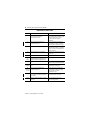
Use this manual as a guide to install the ControlLogix™ DeviceNet™
Scanner Module. The following table identifies what this manual
contains and where to find specific information.
Topic
See Page
European Communities (EC) Directive Compliance
3
Preventing Electrostatic Discharge
4
Understand the Module’s Software Features
5
Identify Module Components
6
Prepare to Install the Module
7
Installing or Removing the Module Under Power
8
Determine Module Slot Location
9
Install the Module
10
Remove or Replace the Module
11
Wire the DeviceNet Connector
12
Connect the Module to the DeviceNet Network
13
Apply Chassis Power
13
Using the Manual Configuration Pushbutton
14
Interpreting the Alphanumeric Display
16
Interpreting the LED Status Indicators
19
ControlLogix Controller Interface
21
Hazardous Location Information
25
Specifications
27
Publication 1756-IN566B-EN-P - April 2001
2 ControlLogix DeviceNet Scanner Module
Throughout this manual we use the following notes to make you
aware of safety considerations:
WARNING
!
ATTENTION
!
Identifies information about practices or
circumstances that have the potential to create an
explosion hazard.
Identifies information about other practices or
circumstances that can lead to personal injury or
death, property damage or economic loss.
Warning and Attention statements help you to:
• identify a hazard
• avoid a hazard
• recognize the consequences
We use the following note to call attention to critical information:
IMPORTANT
Identifies information that is critical for successful
application and understanding of the product.
Change bars are used to indicate information that has changed or
been added since the previous version of these instructions.
Publication 1756-IN566B-EN-P - April 2001
ControlLogix DeviceNet Scanner Module 3
European Communities (EC) Directive Compliance
If this product has the CE mark it is approved for installation within
the European Union and EEA regions. It has been designed and
tested to meet the following directives.
EMC Directive
This product is tested to meet the Council Directive 89/336/EC
Electromagnetic Compatibility (EMC) by applying the following
standards, in whole or in part, documented in a technical
construction file:
• EN 50081-2 EMC — Generic Emission Standard, Part 2 —
Industrial Environment
• EN 50082-2 EMC — Generic Immunity Standard, Part 2 —
Industrial Environment
This product is intended for use in an industrial environment.
Low Voltage Directive
This product is tested to meet Council Directive 73/23/EEC Low
Voltage, by applying the safety requirements of EN 61131-2
Programmable Controllers, Part 2 - Equipment Requirements and
Tests.
For specific information required by EN 61131-2, see the appropriate
sections in this publication, as well as the following Allen-Bradley
publications:
• Industrial Automation Wiring and Grounding Guidelines,
publication 1770-4.1
• Automation Systems Catalog, publication B113
Open style devices must be provided with environmental and safety
protection by proper mounting in enclosures designed for specific
application conditions. See NEMA Standards publication 250 and IEC
publication 529, as applicable, for explanations of the degrees of
protection provided by different types of enclosure.
Publication 1756-IN566B-EN-P - April 2001
4 ControlLogix DeviceNet Scanner Module
Enclosure and Environmental Requirements Specific To This Product
This product must be mounted within a suitable system enclosure to
prevent personal injury resulting from accessibility to live parts. The
interior of this enclosure must be accessible only by the use of a tool.
This industrial control equipment is intended to operate in a Pollution
Degree 2 environment, in overvoltage category II applications, (as
defined in IEC publication 664A) at altitudes up to 2000 meters
without derating.
Preventing Electrostatic Discharge
The DeviceNet scanner module is sensitive to electrostatic discharge.
ATTENTION
!
This module is sensitive to electrostatic discharge.
Electrostatic discharge can damage integrated
circuits or semiconductors if you touch backplane
connector pins. Follow these guidelines when you
handle the module:
• Touch a grounded object to discharge static
potential.
• Wear an approved wrist-strap grounding
device.
• Do not touch the backplane connector or
connector pins.
• Do not touch circuit components inside the
module.
• If available, use a static-safe work station.
• When not in use, keep the module in its
static-shield bag.
Publication 1756-IN566B-EN-P - April 2001
ControlLogix DeviceNet Scanner Module 5
Understand the Module’s Software Features
The 1756-DNB module has the software features described in the
following sections. You activate these features by using RSNetWorx
for DeviceNet™ software (catalog no. 9357-DNETL3). For more
information, refer to the appropriate RSNetWorx for DeviceNet
documentation, and to the 1756-DNB Scanner User Manual,
publication 1756-UM515C-EN-P.
Slave Mode
The slave mode feature allows processor-to-processor
communication. It does this by allowing the scanner to perform as a
slave device to another master on the network.
Like other slaves, the scanner module exchanges data with only one
master when it is in slave mode. You control what information is
exchanged through the scan list configuration and associated
mapping functions of RSNetWorx for DeviceNet software.
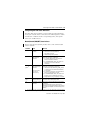
The 1756-DNB can function in the following modes:
Scanner is in this mode when it
Null
Master
contains an empty or disabled scan list (out-of-box default).
serves as a master to one or more slaves but is not
simultaneously serving as a slave to another master.
Slave
serves as a slave to another master.
Dual
serves as both a master to one or more slaves and as a slave to
another master simultaneously.
Change of State
The scanner module can send and receive data on a change of state
basis with slave devices that also have this feature. Data is sent:
• whenever a data change occurs, or
• at a user-configurable heartbeat rate
Publication 1756-IN566B-EN-P - April 2001
6 ControlLogix DeviceNet Scanner Module
Change of state increases system performance by reducing network
traffic, since data is only sent on an as-needed basis. Use RSNetWorx
for DeviceNet software to activate this feature.
Cyclic I/O
The scanner module can send and receive data on a cyclic basis with
slave devices that also have this feature.
Cyclic I/O increases system performance by reducing network traffic,
since data is only sent at a user-configurable rate. Use RSNetWorx for
DeviceNet software to activate this feature.
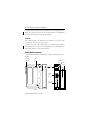
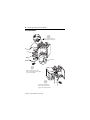
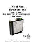
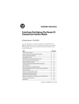
Identify Module Components
Use the following figure to identify the external components of the
module.
Backplane
Connector
Product
Label
Health and
Status Indicators
DeviceNetTM
Front
Panel
Label
MOD/NET I/O
OK
Wiring
Color
Codes
DeviceNet
Connector
Side View
Publication 1756-IN566B-EN-P - April 2001
Door
Front View
ControlLogix DeviceNet Scanner Module 7
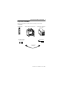
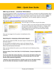
Prepare to Install the Module
Before you install the module, make sure that you have these
components.
1756-DNB module
1756-A4, 1756-A7, or 1756-A10 chassis
DeviceNet open-style or
10-position connector
1756-PA72/75 or 1756-PB72/75
power supply
small screwdriver
DeviceNet truck
or drop cable
Publication 1756-IN566B-EN-P - April 2001
8 ControlLogix DeviceNet Scanner Module
Installing or Removing the Module Under Power
This module is designed to be installed or removed while chassis
power is applied.
WARNING
!
When you insert or remove a module while
backplane power is on, an electrical arc may
occur. An electrical arc can cause personal injury
or property damage by:
• sending an erroneous signal to your system’s
field device causing unintended machine
motion or loss of process control
• causing an explosion in a hazardous
environment
Repeated electrical arcing causes excessive wear
to contacts on both the module and its mating
connector. Worn contacts may create electrical
resistance that can affect module operation.
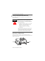
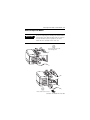
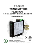
Prepare the Chassis for Module Installation
Before you install the module, you must install and connect a
ControlLogix chassis and power supply. A 4-slot chassis with a power
supply is shown below.
Power
Supply
Publication 1756-IN566B-EN-P - April 2001
1756-A4
Chassis
ControlLogix DeviceNet Scanner Module 9
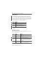
For information on installing these products, refer to the publications
listed in the following table.
Chassis
Type
Series B: 1756-A4, -A7, -A10, -A13
Chassis
Installation
Power
Supply
Power Supply
Installation
Pub. No.
1756-IN080
1756-PA72/B
Pub. No.
1756-5.67
1756-PB72/B
1756-PA75/A
1756-PB75/A
Pub. No.
1756-5.78
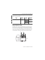
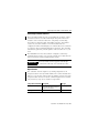
Determine Module Slot Location
This figure shows chassis slot numbering in a 4-slot chassis. Slot 0 is
the first slot and is always located to the right of the power supply.
You can use any size ControlLogix chassis and install the module in
any slot. You can also install multiple 1756-DNB modules in the same
chassis. You can install as many modules as your power supply can
accommodate (i.e., number for which the power supply is rated).
Slot 0
Slot 2
Slot 1
Slot 3
Power Supply
Chassis
Publication 1756-IN566B-EN-P - April 2001
10 ControlLogix DeviceNet Scanner Module
Install the Module
1
Align the circuit board with top
and bottom guides in the chassis.
POWER
Circuit board
2
Slide the module into the chassis.
Make sure the module properly connects
to the chassis backplane.
3
The module is fully installed
when it is flush with the power
supply or other installed modules.
Publication 1756-IN566B-EN-P - April 2001
ControlLogix DeviceNet Scanner Module 11
Remove or Replace the Module
If you are replacing an existing 1756-DNB module
with another 1756-DNB module and you want to
resume identical system operation, you must
install the new module in the same slot.
IMPORTANT
1
Push on upper and lower module
tabs to disengage them.
POWER
POWER
2
Slide the module out of the chassis.
Publication 1756-IN566B-EN-P - April 2001
12 ControlLogix DeviceNet Scanner Module
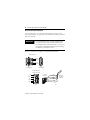
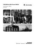
Wire the DeviceNet Connector
Use an open-style 5- or 10-position linear plug to connect to the
DeviceNet network. An open-style 10-position linear plug is provided
with your module.
For detailed DeviceNet connection information,
see the DeviceNet Cable System Planning and
Installation Manual, publication DN-6.7.2. Also see
the Industrial Automation Wiring and Grounding
Guidelines, publication 1770-4.1.
IMPORTANT
Wire the connector according to the following illustrations.
Color chips (dots)
Red dot
White dot
Blue dot
Black dot
5-position plug
10-position plug
Module label shows
wiring color scheme
10-position
linear plug
Red
White
Bare
Blue
D
D
D
D
D
Black
20479-M
Publication 1756-IN566B-EN-P - April 2001
Red
White
Bare
Blue
Black
20474-
DeviceNet
drop line or
trunk cable
ControlLogix DeviceNet Scanner Module 13
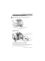
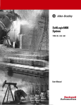
Connect the Module to the DeviceNet Network
Attach the connector to the module’s DeviceNet port as shown
below. Tighten the screws on the connector as needed.
10-position
linear plug
DeviceNet Port Connector
DeviceNet Drop Line or Trunk Connector
Apply Chassis Power
Power supply indicator is green
when power supply is working correctly.
ON
ON
POWER
OFF
POWER
OFF
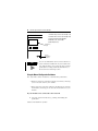
Check the Module Alphanumeric Display on Power-up
Check the module alphanumeric display to determine if the module
is operating. When you apply chassis power, the alphanumeric
display cycles through the following information:
Publication 1756-IN566B-EN-P - April 2001
14 ControlLogix DeviceNet Scanner Module
1. Firmware major revision (01 through 128)
2. Firmware minor revision (01 through 255)
3. Optional Firmware Build Number
4. Baud rate (125, 250, or 500)
5. MAC ID (00 to 63)
DeviceNetTM
Alphanumeric
Display
MOD/NET I/O
OK
Manual
Configuration
Pushbutton
TIP
You can use RSNetWorx for DeviceNet software to
set the baud rate and MAC ID of your module. The
1756-DNB module is also equipped with a manual
pushbutton for setting baud rate and MAC ID, as
described in the following section.
Using the Manual Configuration Pushbutton
The 1756-DNB scanner module has a dual function pushbutton.
• Without a network connection it displays baud rates, allowing
you to select the rate for your module.
• With a network connection it displays the MAC ID or network
node address, allowing you to select the node address for your
module.
If your module is not connected to the network:
1. Select the network baud rate by pushing and holding the
pushbutton.
Publication 1756-IN566B-EN-P - April 2001
ControlLogix DeviceNet Scanner Module 15
The module’s alphanumeric display cycles through the
allowable baud rates (125k 250k, 500k).
2. Release the button when the baud rate you want to select is
shown on the display.
If your module is connected to the network:
1. Select the network node address by pushing in and holding
the pushbutton.
The display starts at the current MAC ID and cycles through all
legitimate the network node addresses (00-63).
2. Release the button when the address number shown on the
display is the number you want to select.
Publication 1756-IN566B-EN-P - April 2001
16 ControlLogix DeviceNet Scanner Module
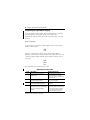
Interpreting the Alphanumeric Display
Your 1756-DNB scanner module displays alphanumeric codes that
provide diagnostic information about your module. The
alphanumeric display flashes the codes at approximately 1 second
intervals.
What is Displayed?
As an example, the display for RUN toggles between the network
address and the mode:
A#01
RUN
If there is a problem, the display shows the network address,
followed by the MAC ID of the problem node, followed by the error
code. The display toggles through these elements until the error is
corrected.
A#01
N#33
E#72
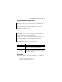
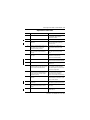
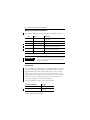
The following table summarizes the codes.
Alphanumeric Status Codes
Code
Description
Recommended Action
70
Scanner failed Duplicate Node
Address check
Change the scanner address to
another available one. The node
address you selected is already in use
on that network.
71
Illegal data in scan list table (node
number alternately flashes).
Reconfigure the scan list table and
remove any illegal data.
72
Slave device stopped communicating
(node number alternately flashes).
Inspect the slave devices and verify
connections.
73
Device’s identity information does not
match electronic key in scan list table
entry (node number alternately
flashes).
Verify that the correct device is at this
node number. Make sure the device at
the scrolling node address matches
the desired electronic key (vendor,
product code, product type, etc.).
Publication 1756-IN566B-EN-P - April 2001
ControlLogix DeviceNet Scanner Module 17
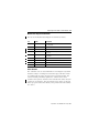
Alphanumeric Status Codes
Code
Description
Recommended Action
74
Data overrun on port detected.
Modify your configuration and check
for invalid data. Check network
communication traffic.
75
No traffic detected on the network.
Check the network configuration.
76
No direct network traffic for scanner
detected.
None. The scanner hears other
network communication, but none
directed to itself.
77
Data size expected by the device does Reconfigure your module for the
not match scan list entry (node
correct transmit and receive data
number alternately flashes).
sizes.
78
Slave device in scan list table does
not exist (node number alternately
flashes).
Add the device to the network, or
delete the scan list entry for that
device.
79
Scanner has failed to transmit a
message.
Make sure that your module is
connected to a valid network.
Check for disconnected cables.
80
Scanner is in IDLE mode.
Put controller in RUN mode. Enable
RUN bit in Module Command Register.
81
Scanner is in FAULT mode.
Check Module Command Register for
FAULT bit set.
82
Error detected in sequence of
Check scan list table entry for slave
fragmented I/O messages from device device to make sure that input and
(node number alternately flashes).
output data lengths are correct. Check
slave device configuration.
83
Slave device is returning error
responses when scanner attempts to
communicate with it (node number
alternately flashes).
Check accuracy of scan list table entry.
Check slave device configuration.
Slave device may be in another
master’s scan list. Reboot slave device.
84
Scanner is initializing the DeviceNet
network.
None. This code clears itself once
scanner attempts to initialize all slave
devices on the network.
85
Data size was incorrect for this device Slave device is transmitting incorrect
at runtime.
length data. Try replacing slave device.
86
Device is producing zero length data
(idle state) while scanner is in Run
Mode.
90
User has disabled communication port Check Module Command Register for
DISABLE bit set.
Check device configuration and slave
node status.
Publication 1756-IN566B-EN-P - April 2001
18 ControlLogix DeviceNet Scanner Module
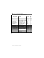
Alphanumeric Status Codes
Code
Description
Recommended Action
91
Bus-off condition detected on comm
port. Scanner is detecting
communication errors.
Check DeviceNet connections and
physical media integrity. Check system
for failed slave devices or other
possible sources of network
interference.
92
No network power detected on
communication port.
Provide network power. Make sure
that module drop cable is providing
network power to module comm. port.
95
Application FLASH update in progress. None. Do not disconnect the module
while application FLASH is in progress.
You will lose any existing data in the
scanner’s memory.
97
Scanner halted by user command.
98
Check Module Command Register for
HALT bit set.
General firmware error.
Replace module.
A#00
to
A#63
Normal operation. The numeric
display matches the scanner’s node
address on the DeviceNet network.
Do nothing.
IDLE
Scanner is in IDLE mode.
Put controller in RUN mode. Enable
RUN bit in Module Command Register.
Network
Disabled
User has disabled communication
port.
Reconfigure your module. check
Module Command Register.
No
Network
Power
No network power detected on
communication port.
Provide network power. Make sure
that scanner drop cable is providing
network power to scanner
communication port.
NoRX
No scan list is active in the module or
no messages have been received by
the scanner.
Enter a scan list. Check DeviceNet
connection on front of module.
NoTX
No direct network traffic for scanner
detected.
None. The scanner hears other
network communication.
Publication 1756-IN566B-EN-P - April 2001
ControlLogix DeviceNet Scanner Module 19
Interpreting the LED Status Indicators
The three LED status indicators on the module provide information
about your network and its connections. The following tables outline
the indicator condition and the corresponding status, and explain
what each condition means.
Module/Network (MOD/NET) Status Indicator
This bi-color (green/red) LED provides device and communication
status as follows:
Condition
Status
Indicates
off
not powered/
not online
Device is not online.
• The device has not completed the
Dup_MAC_ID test yet.
• The device may not be powered.
green
device operational
AND online and
connected
Device is operating in a normal condition and is
online with connections established.
• For a group 2 Only device, this means the
device is allocated to a Master.
• For a UCMM capable device, this means the
device has one or more established
connections.
flashing
green(1)
device operational
AND online and not
connected
or
device online and
device needs
commissioning
The device is operating in a normal condition and is
online with no connections established.
• The device has passed the Dup_MAC_ID test,
is online, but has no established connections
to other nodes.
• For a Group 2 only device, this means that the
device is not allocated to a master.
• For a UCMM capable device, this means that
the device has no established connections.
• Configuration missing, incomplete, or incorrect.
flashing
red(1)
minor fault and/or
connection time-out
Recoverable fault.and/or one or more I/O
connections are in the timed-out state.
red
critical fault or critical
link failure
Device has an unrecoverable fault and may need to
be replaced.
Failed communication device. The device has
detected an error (duplicate MAC ID or bus-off) that
has rendered it incapable of communicating on the
network.
(1)
The flash rate of the LED is approximately 1 flash per second. The LED should be on for approximately
0.5 seconds and off for approximately 0.5 seconds.
Publication 1756-IN566B-EN-P - April 2001
20 ControlLogix DeviceNet Scanner Module
I/O Status Indicator
This bi-color (green/red) LED indicates the status of the 1756-DNB’s
I/O scanning state. The I/O Status LED informs you whether this
device has outputs under control and whether any outputs or inputs
are active (outputs active, inputs producing, etc.) or faulted. The LED
reflects the mod/state of the inputs and outputs, not necessarily the
on/off condition of the I/O points themselves.
Condition
Indicates
off
Scanner is not online. Check network power.
green
Scanner is in RUN mode, outputs are under control,
and inputs are being consumed.
flashing
green(1)
Scanner is in IDLE mode, outputs are not under
control, and inputs are being consumed.
(1)
The flash rate of the LED is approximately 1 flash per second. The LED
should be on for approximately 0.5 seconds and off for approximately 0.5
seconds.
Health (OK) Status Indicator
This bi-color (green/red) LED indicates whether the device has power
and is operating properly.
Condition
Status
Indicates
off
no power
No power applied to device. Apply chassis power.
Verify module is completely inserted into chassis
and backplane.
green
device operational
Device is operating normally. The DNB has at least
one connection to it from a controller.
flashing
green(1)
device in standby
The device is operating correctly; however, no
controller is controlling it. Verify that the DNB
module is properly configured in the controller’s I/O
configuration.
red
unrecoverable fault
or
device self testing
Device has an unrecoverable fault; repair or replace
it, or
Device is in self test during power-up.
(1)
The flash rate of the LED is approximately 1 flash per second. The LED should be on for approximately
0.5 seconds and off for approximately 0.5 seconds.
Publication 1756-IN566B-EN-P - April 2001
ControlLogix DeviceNet Scanner Module 21
ControlLogix Controller Interface
The 1756-DNB module supports several different size input, output,
and status structures over the ControlLogix backplane. These I/O
structures were created to reduce the complexity of connecting
DeviceNet I/O and status data with ladder programs. The module
creates all 3 structures whether or not DeviceNet nodes are
configured or online. The RSLogix 5000 software directs the controller
to connect to these predefined default I/O structures. The controller
automatically performs periodic updates of the structures on a cyclic
basis.
The RSNetWorx for DeviceNet software configures scanlist map
segments that are used to copy specific portions of I/O data between
the I/O structures and DeviceNet network packets.
IMPORTANT
The 1756-DNB scanner supports ControlLogix
connections with only one controller at a time.
Output Structure
The controller controls output I/O by writing output data to an
output structure in the 1756-DNB module. The scanner module then
delivers a copy of these output values to modules on DeviceNet. The
output structure consists of a 32-bit command register and a variable
size 32-bit array of up to 123 words for output data.
Output Structure Element Description
module command register
output_data
Data Type
This 32-bit register consists of
1 x 32-bit register
several bits that affect the module’s
behavior on the network.
123 x 32-bit data array
Publication 1756-IN566B-EN-P - April 2001
22 ControlLogix DeviceNet Scanner Module
Module Command Register Bit Definitions
The bits of the Module Command Register are defined as follows:
Bit
Name
Description
0
Run
1 = run mode
0 = idle mode
1
Fault
1 = fault network
2
DisableNetwork
1 = disable network
3
HaltScanner
1 = halt module
(the DNB module ceases all operation.)
4
Reset
1 = reset module
(put back to 0 to resume operation.)
{Reserved}
unused
5 - 31
IMPORTANT
If the module is halted because the HaltScanner
bit is set, power must be physically recycled to
restart the module.
Input Structure
The controller receives input I/O by reading input data from an input
structure in the 1756-DNB module. The scanner module receives
input data from DeviceNet modules and delivers a copy of these
values to the controller. The input structure consists of one 32-bit
status register and a variable size 32-bit array of up to 124 words for
input data. The 32-bit status register reflects the current state of
several key module-level operational parameters.
The input structure consists of these data elements.
Input Structure Element
Data Type
module status register
1 x 32-bit register
input_data
123 x 32-bit variable size
data array
Publication 1756-IN566B-EN-P - April 2001
ControlLogix DeviceNet Scanner Module 23
Module Status Register Bit Definitions
The bits of the Module Status Register are defined as follows:
Bit
Name
Description
0
Run
1 = in run mode.
0 = in idle mode.
1
Fault
1 = network is faulted.
2
DisableNetwork
1 = network is disabled.
3
DeviceFailure
1 = device failure exists (examine the status structure
for causes).
4
AutoverifyFailure
1 = at least one device has failed to be initialized by
the scanner.
5
CommFailure
1 = communication failure exists.
6
DupNodeFail
1 = failure due to duplicate node address.
7
DnetPowerDetect
1 = DeviceNet power failure.
{Reserved}
unused
8 - 31
Status Structure
The controller receives status information concerning the 1756-DNB
module’s ability to exchange DeviceNet messages with other nodes
by reading from the status structure in the 1756-DNB module. The
scanner module periodically updates the contents of the status
structure and copies its contents to the controller. The status structure
consists of several tables. The bit position of each of the 64 bits that
make up a given status table directly corresponds to the node address
of a device.
Publication 1756-IN566B-EN-P - April 2001
24 ControlLogix DeviceNet Scanner Module
The status structure consists of these data elements:
Status Structure
Element
Description
Data Type
ScanCounter
counter incremented each I/O scan
32-bit
DeviceFailureRegister
device failed bit table; 1 = failed
64-bit
DINTS
10
AutoverifyFailureRegister device I/O size does not match
64-bit
scanner’s internal table; 1 = mismatch
DeviceIdleRegister
device is idle bit table; 1 = idle
64-bit
ActiveNodeRegister
node online bit table; 1 = online
64-bit
StatusDisplay
ASCII representation of DNB
alphanumeric display
4-byte
ScannerDeviceStatus
Scanner device status:
4-byte binary
ScannerAddress
DeviceNet address of DNB module
8-bit binary
ScannerStatus
status of 1756-DNB module
8-bit binary
11
ScrollingDeviceAddress scrolls through DeviceNet nodes once 8-bit binary
per second by address and status
8-bit binary
(0 = no faults).
ScrollingDeviceStatus
ReservedArray
future expansion (20 bytes)
20 x 8-bit
16
DeviceStatus
DeviceNet node status array,
byte per device
64 x 8-bit
24/32
Publication 1756-IN566B-EN-P - April 2001
ControlLogix DeviceNet Scanner Module 25
Hazardous Location Information
The following information applies when operating this equipment in
hazardous locations:
Products marked “CL I, DIV 2, GP A, B, C, D” are suitable for use in
Class I Division 2 Groups A, B, C, D, Hazardous Locations and
nonhazardous locations only. Each product is supplied with markings
on the rating nameplate indicating the hazardous location
temperature code. When combining products within a system, the
most adverse temperature code (lowest “T” number) may be used to
help determine the overall temperature code of the system.
Combinations of equipment in your system are subject to
investigation by the local Authority Having Jurisdiction at the time of
installation.
WARNING
!
EXPLOSION HAZARD
• Do not disconnect equipment unless power
has been removed or the area is known to be
nonhazardous.
• Do not disconnect connections to this
equipment unless power has been removed
or the area is known to be nonhazardous.
Secure any external connections that mate to
this equipment by using screws, sliding
latches, threaded connectors, or other means
provided with this product.
• Substitution of components may impair
suitability for Class I, Division 2.
• If this product contains batteries, they must
only be changed in an area known to be
nonhazardous.
Publication 1756-IN566B-EN-P - April 2001
26 ControlLogix DeviceNet Scanner Module
Informations sur l’utilisation de cet équipement en environnements
dangereux:
Les produits marqués “CL I, DIV 2, GP A, B, C, D” ne conviennent
qu’à une utilisation en environnements de Classe I Division 2
Groupes A, B, C, D dangereux et non dangereux. Chaque produit est
livré avec des marquages sur sa plaque d’identification qui indiquent
le code de température pour les environnements dangereux. Lorsque
plusieurs produits sont combinés dans un système, le code de
température le plus défavorable (code de température le plus faible)
peut être utilisé pour déterminer le code de température global du
système. Les combinaisons d’équipements dans le système sont
sujettes à inspection par les autorités locales qualifiées au moment de
l’installation.
AVERTISSEMENT
!
RISQUE D’EXPLOSION
• Couper le courant ou s’assurer que
l’environnement est classé non dangereux
avant de débrancher l’équipement.
• Couper le courant ou s’assurer que
l’environnement est classé non dangereux
avant de débrancher les connecteurs. Fixer
tous les connecteurs externes reliés à cet
équipement à l’aide de vis, loquets
coulissants, connecteurs filetés ou autres
moyens fournis avec ce produit.
• La substitution de composants peut rendre cet
équipement inadapté à une utilisation en
environnement de Classe 1, Division 2.
• S’assurer que l’environnement est classé non
dangereux avant de changer les piles.
Publication 1756-IN566B-EN-P - April 2001
ControlLogix DeviceNet Scanner Module 27
Specifications
Parameter
Specification
Module Location
any slot in the ControlLogix chassis
Maximum Backplane Current Load
600mA @ 5.0V dc and 3mA @ 24V dc
from ControlLogix chassis backplane
Maximum DeviceNet Current Load
90mA maximum @11-25V dc
30mA typical @ 11-25V dc
Power Dissipation
5.3W maximum
Environmental Conditions
Operational Temperature:
Storage Temperature:
Relative Humidity:
0 to 60°C (32° to 140°F)
-40° to 85°C (-40° to 185°F)
5-95% without condensation
Shock Unpackaged
30g operational
50g non-operational
Vibration Unpackaged
5g from 10-150Hz
Conductors
Category 2(1)
Agency Certification
(when product is marked)
Listed Industrial Control Equipment
Certified Process control Equipment
Certified Class I, Division 2, Group A,B,C,D
Approved class I, Division 2, Group A,B,C,D
Marked for all applicable directives
Marked for all applicable acts
N223
(1)
Refer to the Industrial Automation Wiring and Grounding Guidelines, publication 1770-4.1.
Publication 1756-IN566B-EN-P - April 2001
ControlLogix is a trademark of Rockwell Automation.
DeviceNet is a trademark of Open DeviceNet Vendors Association (ODVA).
RSLogix 5000 and RSNetWorx for DeviceNet are trademarks of Rockwell Software Inc.
Publication 1756-IN566B-EN-P - April 2001
Supersedes Publication 1756-5.66 - May 1998
PN 957536-69
© 2001 Rockwell International Corporation. Printed in USA