1
University of Manchester
School of Computer Science
Project Report 2012
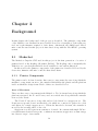
Improving the Makerbot 3D Printer
Author:
Jonathan Heathcote
Supervisor:
Alasdair Rawsthorne
Abstract
Improving the Makerbot 3D Printer
Author: Jonathan Heathcote
Personal 3D printers allow anyone to manufacture complex physical objects on demand
with minimal skill and effort. The Makerbot Cupcake CNC is a low cost, easy to build
3D printer with a wide community of users. Though relatively capable, the machine is
held back by its primitive control electronics and microcontroller.
New electronics based around a more powerful ARM microcontroller were produced along
with new firmware to control the printer. The system was built on the widely used
FreeRTOS and uses the µIP TCP/IP stack allowing a clean, easily extended design to be
implemented.
The new system improved the print quality achievable by the printer thanks to improved
timing accuracy. Additional sensors also allowed the printer to act with increased independence.
Supervisor: Alasdair Rawsthorne
Acknowledgements
Thanks are due to my supervisor, Alasdair Rawsthorne, who has been
both supportive and helpful throughout every stage of the project. Also,
many thanks to Dave Bowden who constantly supplied me with all manner of
tools and components at short notice throughout. Finally, thanks too to my
parents and girlfriend who’ve been kind enough to put up with my ranting
and assist with proof-reading while working on this report.
2
Contents
1 Introduction
1.1 Applications . . . . . .
1.2 Makerbot . . . . . . .
1.3 Project Motivation and
1.4 Report Outline . . . .
.
.
.
.
.
.
.
.
.
.
.
.
.
.
.
.
.
.
.
.
.
.
.
.
.
.
.
.
.
.
.
.
.
.
.
.
.
.
.
.
.
.
.
.
.
.
.
.
.
.
.
.
.
.
.
.
10
10
11
11
13
2 Background
2.1 Makerbot . . . . . . . . . . . . . . . . . . . . . .
2.1.1 Printer Components . . . . . . . . . . . .
2.1.2 Electronics . . . . . . . . . . . . . . . . . .
2.1.3 Microcontrollers . . . . . . . . . . . . . . .
2.1.4 Firmware . . . . . . . . . . . . . . . . . .
2.1.5 G-Code . . . . . . . . . . . . . . . . . . .
2.1.6 Support Software . . . . . . . . . . . . . .
2.2 ARM & Mbed . . . . . . . . . . . . . . . . . . . .
2.2.1 Mbed . . . . . . . . . . . . . . . . . . . .
2.2.2 NXP LPC1768 . . . . . . . . . . . . . . .
2.3 Real-Time Operating Systems . . . . . . . . . . .
2.3.1 Differences With Non-Real-Time Systems
2.3.2 FreeRTOS . . . . . . . . . . . . . . . . . .
.
.
.
.
.
.
.
.
.
.
.
.
.
.
.
.
.
.
.
.
.
.
.
.
.
.
.
.
.
.
.
.
.
.
.
.
.
.
.
.
.
.
.
.
.
.
.
.
.
.
.
.
.
.
.
.
.
.
.
.
.
.
.
.
.
.
.
.
.
.
.
.
.
.
.
.
.
.
.
.
.
.
.
.
.
.
.
.
.
.
.
.
.
.
.
.
.
.
.
.
.
.
.
.
.
.
.
.
.
.
.
.
.
.
.
.
.
.
.
.
.
.
.
.
.
.
.
.
.
.
.
.
.
.
.
.
.
.
.
.
.
.
.
.
.
.
.
.
.
.
.
.
.
.
.
.
.
.
.
.
.
.
.
.
.
.
.
.
.
14
14
14
16
16
16
17
17
17
18
18
18
19
19
.
.
.
.
.
.
.
.
.
.
20
20
21
21
22
22
22
22
22
23
23
4 Implementation
4.1 Electronics . . . . . . . . . . . . . . . . . . . . . . . . . . . . . . . . . . .
4.1.1 Layout & Board . . . . . . . . . . . . . . . . . . . . . . . . . . . .
24
24
26
. . . .
. . . .
Goals
. . . .
.
.
.
.
.
.
.
.
.
.
.
.
3 Design
3.1 Firmware . . . . . . . . . . . . . .
3.1.1 Network Interface . . . . . .
3.1.2 G-code Processing Pipeline .
3.1.3 G-code Interpreter . . . . .
3.1.4 Drivers . . . . . . . . . . . .
3.1.5 Safety . . . . . . . . . . . .
3.2 Electronics & Hardware . . . . . .
3.2.1 Stepper Control . . . . . . .
3.2.2 Heater & DC Motor Control
3.2.3 End-stops . . . . . . . . . .
3
.
.
.
.
.
.
.
.
.
.
.
.
.
.
.
.
.
.
.
.
.
.
.
.
.
.
.
.
.
.
.
.
.
.
.
.
.
.
.
.
.
.
.
.
.
.
.
.
.
.
.
.
.
.
.
.
.
.
.
.
.
.
.
.
.
.
.
.
.
.
.
.
.
.
.
.
.
.
.
.
.
.
.
.
.
.
.
.
.
.
.
.
.
.
.
.
.
.
.
.
.
.
.
.
.
.
.
.
.
.
.
.
.
.
.
.
.
.
.
.
.
.
.
.
.
.
.
.
.
.
.
.
.
.
.
.
.
.
.
.
.
.
.
.
.
.
.
.
.
.
.
.
.
.
.
.
.
.
.
.
.
.
.
.
.
.
.
.
.
.
.
.
.
.
.
.
.
.
.
.
.
.
.
.
.
.
.
.
.
.
.
.
.
.
.
.
.
.
.
.
.
.
.
.
.
.
.
.
.
.
.
.
.
.
.
.
.
.
.
.
.
.
.
.
.
.
.
.
4.2
4.3
4.4
4.5
4.1.2 Heaters & DC Motors .
4.1.3 Thermistors . . . . . . .
4.1.4 Stepper Motors . . . . .
4.1.5 End-stops . . . . . . . .
4.1.6 Power . . . . . . . . . .
4.1.7 Ethernet . . . . . . . . .
Firmware . . . . . . . . . . . .
4.2.1 FreeRTOS on the Mbed
4.2.2 Temperature Control . .
4.2.3 Stepper Control . . . . .
4.2.4 G-Code Interpreter . . .
4.2.5 Printer Controller . . . .
4.2.6 Network Interface . . . .
Utilities . . . . . . . . . . . . .
Safety . . . . . . . . . . . . . .
4.4.1 Heater Indicator LEDs .
4.4.2 Power-on Behaviour . .
4.4.3 Stop Button . . . . . . .
4.4.4 Watchdog Timer . . . .
Methodology & Tools . . . . . .
4.5.1 Methodology . . . . . .
4.5.2 Languages . . . . . . . .
4.5.3 Version Control . . . . .
4.5.4 Debugging . . . . . . . .
5 Testing & Evaluation
5.1 Electronics . . . . . . .
5.1.1 MOSFETs . . .
5.1.2 End-stops . . .
5.1.3 ATX PSU . . .
5.2 FreeRTOS . . . . . . .
5.3 µIP & Networking . .
5.4 Temperature Readings
5.5 PID Control . . . . . .
5.6 Stepper Control . . . .
5.6.1 Timing . . . . .
5.6.2 Stepping . . . .
5.7 End-stops . . . . . . .
5.8 Buffer Utilisation . . .
5.9 System Testing . . . .
5.9.1 Synthetic Tests
5.9.2 Test Objects . .
.
.
.
.
.
.
.
.
.
.
.
.
.
.
.
.
.
.
.
.
.
.
.
.
.
.
.
.
.
.
.
.
.
.
.
.
.
.
.
.
.
.
.
.
.
.
.
.
.
.
.
.
.
.
.
.
.
.
.
.
.
.
.
.
.
.
.
.
.
.
.
.
.
.
.
.
.
.
.
.
.
.
.
.
.
.
.
.
.
.
.
.
.
.
.
.
.
.
.
.
.
.
.
.
.
.
.
.
.
.
.
.
.
.
.
.
.
.
.
.
.
.
.
.
.
.
.
.
.
.
.
.
.
.
.
.
.
.
.
.
.
.
.
.
.
.
.
.
.
.
.
.
.
.
.
.
.
.
.
.
4
.
.
.
.
.
.
.
.
.
.
.
.
.
.
.
.
.
.
.
.
.
.
.
.
.
.
.
.
.
.
.
.
.
.
.
.
.
.
.
.
.
.
.
.
.
.
.
.
.
.
.
.
.
.
.
.
.
.
.
.
.
.
.
.
.
.
.
.
.
.
.
.
.
.
.
.
.
.
.
.
.
.
.
.
.
.
.
.
.
.
.
.
.
.
.
.
.
.
.
.
.
.
.
.
.
.
.
.
.
.
.
.
.
.
.
.
.
.
.
.
.
.
.
.
.
.
.
.
.
.
.
.
.
.
.
.
.
.
.
.
.
.
.
.
.
.
.
.
.
.
.
.
.
.
.
.
.
.
.
.
.
.
.
.
.
.
.
.
.
.
.
.
.
.
.
.
.
.
.
.
.
.
.
.
.
.
.
.
.
.
.
.
.
.
.
.
.
.
.
.
.
.
.
.
.
.
.
.
.
.
.
.
.
.
.
.
.
.
.
.
.
.
.
.
.
.
.
.
.
.
.
.
.
.
.
.
.
.
.
.
.
.
.
.
.
.
.
.
.
.
.
.
.
.
.
.
.
.
.
.
.
.
.
.
.
.
.
.
.
.
.
.
.
.
.
.
.
.
.
.
.
.
.
.
.
.
.
.
.
.
.
.
.
.
.
.
.
.
.
.
.
.
.
.
.
.
.
.
.
.
.
.
.
.
.
.
.
.
.
.
.
.
.
.
.
.
.
.
.
.
.
.
.
.
.
.
.
.
.
.
.
.
.
.
.
.
.
.
.
.
.
.
.
.
.
.
.
.
.
.
.
.
.
.
.
.
.
.
.
.
.
.
.
.
.
.
.
.
.
.
.
.
.
.
.
.
.
.
.
.
.
.
.
.
.
.
.
.
.
.
.
.
.
.
.
.
.
.
.
.
.
.
.
.
.
.
.
.
.
.
.
.
.
.
.
.
.
.
.
.
.
.
.
.
.
.
.
.
.
.
.
.
.
.
.
.
.
.
.
.
.
.
.
.
.
.
.
.
.
.
.
.
.
.
.
.
.
.
.
.
.
.
.
.
.
.
.
.
.
.
.
.
.
.
.
.
.
.
.
.
.
.
.
.
.
.
.
.
.
.
.
.
.
.
.
.
.
.
.
.
.
.
.
.
.
.
.
.
.
.
.
.
.
.
.
.
.
.
.
.
.
.
.
.
.
.
.
.
.
.
.
.
.
.
.
.
.
.
.
.
.
.
.
.
.
.
.
.
.
.
.
.
.
.
.
.
.
.
.
.
.
.
.
.
.
.
.
.
.
.
.
.
.
.
.
.
.
.
.
.
.
.
.
.
.
.
.
.
.
.
.
.
.
.
.
.
.
.
.
.
.
.
.
.
.
.
.
.
.
.
.
.
.
.
.
.
.
.
.
.
.
.
.
.
.
.
.
.
.
.
.
.
.
.
.
.
.
.
.
.
.
.
.
.
.
.
.
.
.
.
.
.
.
.
.
.
.
.
.
.
.
.
.
.
.
.
.
.
.
.
.
.
.
.
.
.
.
.
.
.
.
.
.
.
.
.
.
.
.
.
.
.
.
.
.
.
.
.
.
.
.
.
.
.
.
.
.
.
.
.
.
.
.
.
.
.
.
.
.
.
.
.
.
.
.
.
.
.
.
.
.
.
.
.
.
.
.
.
.
.
.
.
.
.
.
.
.
.
.
.
.
.
.
.
.
.
.
.
.
.
.
.
.
.
.
.
.
.
.
.
.
.
.
.
.
.
.
.
.
.
.
.
.
.
.
.
.
.
.
.
.
.
.
.
.
.
.
.
.
.
.
.
.
.
.
.
.
.
.
.
.
.
.
.
27
28
29
29
30
31
31
31
32
33
36
37
37
39
41
41
41
41
41
42
42
43
43
43
.
.
.
.
.
.
.
.
.
.
.
.
.
.
.
.
44
44
44
45
45
45
45
47
48
49
49
49
50
50
51
51
53
6 Conclusions & Future Work
6.1 Project Goals . . . . . . . . . . . . .
6.1.1 Electronics Replacement . . .
6.1.2 Microcontroller Improvements
6.1.3 End-stops . . . . . . . . . . .
6.2 Future Work . . . . . . . . . . . . . .
6.2.1 Network Interface . . . . . . .
6.2.2 Endstop Support . . . . . . .
6.2.3 G-Code Support . . . . . . .
6.2.4 Firmware Improvements . . .
6.2.5 Mechanical Improvements . .
6.3 Final Conclusions . . . . . . . . . . .
.
.
.
.
.
.
.
.
.
.
.
.
.
.
.
.
.
.
.
.
.
.
.
.
.
.
.
.
.
.
.
.
.
.
.
.
.
.
.
.
.
.
.
.
.
.
.
.
.
.
.
.
.
.
.
.
.
.
.
.
.
.
.
.
.
.
.
.
.
.
.
.
.
.
.
.
.
.
.
.
.
.
.
.
.
.
.
.
.
.
.
.
.
.
.
.
.
.
.
.
.
.
.
.
.
.
.
.
.
.
.
.
.
.
.
.
.
.
.
.
.
.
.
.
.
.
.
.
.
.
.
.
.
.
.
.
.
.
.
.
.
.
.
.
.
.
.
.
.
.
.
.
.
.
.
.
.
.
.
.
.
.
.
.
.
.
.
.
.
.
.
.
.
.
.
.
.
.
.
.
.
.
.
.
.
.
.
.
.
.
.
.
.
.
.
.
.
.
.
.
.
.
.
.
.
.
.
.
.
.
.
.
.
.
.
.
.
.
.
.
References
57
57
57
57
58
58
58
59
59
59
60
60
61
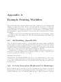
A Example Printing Workflow
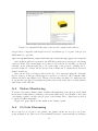
A.1 3D Modelling (OpenSCAD) . . . . . . . . . . .
A.2 G-Code Generation (ReplicatorG & Skeinforge)
A.3 Status Monitoring . . . . . . . . . . . . . . . . .
A.4 G-Code Streaming . . . . . . . . . . . . . . . .
A.5 Printing Process . . . . . . . . . . . . . . . . . .
A.5.1 Warm Up & Self-Clean . . . . . . . . . .
A.5.2 Printing The First Layer . . . . . . . . .
A.5.3 Main Printing Phase . . . . . . . . . . .
A.5.4 Cool-down, Eject and Self-Clean . . . . .
A.6 Final Print . . . . . . . . . . . . . . . . . . . . .
.
.
.
.
.
.
.
.
.
.
64
64
64
65
65
67
67
67
68
69
70
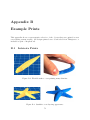
B Example Prints
B.1 Intricate Prints . . . . . . . . . . . . . . . . . . . . . . . . . . . . . . . .
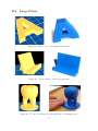
B.2 Large Prints . . . . . . . . . . . . . . . . . . . . . . . . . . . . . . . . . .
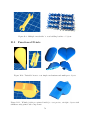
B.3 Functional Prints . . . . . . . . . . . . . . . . . . . . . . . . . . . . . . .
71
71
73
74
C Circuit Diagrams
C.1 Control Electronics .
C.2 End-stop Electronics
C.2.1 Wiring Colour
C.2.2 Schematic . .
.
.
.
.
76
76
79
79
79
.
.
.
.
.
.
.
.
81
81
81
81
81
83
84
86
86
. . . .
. . . .
Codes
. . . .
.
.
.
.
.
.
.
.
.
.
.
.
.
.
.
.
D G-Code Reference
D.1 Language . . . . . . . . . . . . . .
D.1.1 BNF . . . . . . . . . . . . .
D.1.2 Register Types & Behaviour
D.2 Actions . . . . . . . . . . . . . . .
D.2.1 ‘G’ Actions . . . . . . . . .
D.2.2 ‘M’ Actions . . . . . . . . .
D.3 Examples . . . . . . . . . . . . . .
D.3.1 Power On, Heat Up . . . . .
5
.
.
.
.
.
.
.
.
.
.
.
.
.
.
.
.
.
.
.
.
.
.
.
.
.
.
.
.
.
.
.
.
.
.
.
.
.
.
.
.
.
.
.
.
.
.
.
.
.
.
.
.
.
.
.
.
.
.
.
.
.
.
.
.
.
.
.
.
.
.
.
.
.
.
.
.
.
.
.
.
.
.
.
.
.
.
.
.
.
.
.
.
.
.
.
.
.
.
.
.
.
.
.
.
.
.
.
.
.
.
.
.
.
.
.
.
.
.
.
.
.
.
.
.
.
.
.
.
.
.
.
.
.
.
.
.
.
.
.
.
.
.
.
.
.
.
.
.
.
.
.
.
.
.
.
.
.
.
.
.
.
.
.
.
.
.
.
.
.
.
.
.
.
.
.
.
.
.
.
.
.
.
.
.
.
.
.
.
.
.
.
.
.
.
.
.
.
.
.
.
.
.
.
.
.
.
.
.
.
.
.
.
.
.
.
.
.
.
.
.
.
.
.
.
.
.
.
.
.
.
.
.
.
.
.
.
.
.
.
.
.
.
.
.
.
.
.
.
.
.
.
.
.
.
.
.
.
.
.
.
.
.
.
.
.
.
.
.
.
.
.
.
.
.
.
.
.
.
.
.
.
.
.
.
.
.
.
.
.
.
.
.
.
.
.
.
.
.
.
.
.
.
.
.
.
.
.
.
.
.
.
.
.
.
.
.
.
.
.
.
.
.
.
.
.
.
.
.
.
.
.
.
.
.
.
.
.
.
.
.
.
.
.
.
.
.
.
.
.
.
.
.
.
.
.
.
.
.
.
.
.
.
.
.
.
.
.
.
.
.
D.3.2
D.3.3
D.3.4
D.3.5
D.3.6
Power-down . . . . . . .
Skeinforge Print Prefix .
Skeinforge Print Postfix
Home X & Y Axes . . .
Circle . . . . . . . . . .
E Code Documentation
E.1 File Listing . . . . . .
E.2 Firmware . . . . . . .
E.2.1 Dependencies .
E.2.2 Compilation . .
E.2.3 Configuration .
E.3 Utilities . . . . . . . .
E.3.1 Dependencies .
E.3.2 Send . . . . . .
E.3.3 Get . . . . . . .
E.3.4 makebed live.sh
.
.
.
.
.
.
.
.
.
.
.
.
.
.
.
.
.
.
.
.
.
.
.
.
.
.
.
.
.
.
.
.
.
.
.
.
.
.
.
.
.
.
.
.
.
.
.
.
.
.
.
.
.
.
.
.
.
.
.
.
.
.
.
.
.
.
.
.
.
.
.
.
.
.
.
.
.
.
.
.
F Protocol Specifications
F.1 UDP G-code Transmission Protocol
F.1.1 Sender Packets . . . . . . .
F.1.2 Acknowledges . . . . . . . .
F.1.3 Retransmission . . . . . . .
F.1.4 Errors . . . . . . . . . . . .
F.2 Status Monitoring Protocol . . . .
6
.
.
.
.
.
.
.
.
.
.
.
.
.
.
.
.
.
.
.
.
.
.
.
.
.
.
.
.
.
.
.
.
.
.
.
.
.
.
.
.
.
.
.
.
.
.
.
.
.
.
.
.
.
.
.
.
.
.
.
.
.
.
.
.
.
.
.
.
.
.
.
.
.
.
.
.
.
.
.
.
.
.
.
.
.
.
.
.
.
.
.
.
.
.
.
.
.
.
.
.
.
.
.
.
.
.
.
.
.
.
.
.
.
.
.
.
.
.
.
.
.
.
.
.
.
.
.
.
.
.
.
.
.
.
.
.
.
.
.
.
.
.
.
.
.
.
.
.
.
.
.
.
.
.
.
.
.
.
.
.
.
.
.
.
.
.
.
.
.
.
.
.
.
.
.
.
.
.
.
.
.
.
.
.
.
.
.
.
.
.
.
.
.
.
.
.
.
.
.
.
.
.
.
.
.
.
.
.
.
.
.
.
.
.
.
.
.
.
.
.
.
.
.
.
.
.
.
.
.
.
.
.
.
.
.
.
.
.
.
.
.
.
.
.
.
.
.
.
.
.
.
.
.
.
.
.
.
.
.
.
.
.
.
.
.
.
.
.
.
.
.
.
.
.
.
.
.
.
.
.
.
.
.
.
.
.
.
.
.
.
.
.
.
.
.
.
.
.
.
.
.
.
.
.
.
.
.
.
.
.
.
.
.
.
.
.
.
.
.
.
.
.
.
.
.
.
.
.
.
.
.
.
.
.
.
.
.
.
.
.
.
.
.
.
.
.
.
.
.
.
.
.
.
.
.
.
.
.
.
.
.
.
.
.
.
.
.
.
.
.
.
.
.
.
.
.
.
.
.
.
.
.
.
.
.
.
.
.
.
.
.
.
.
.
.
.
.
.
.
.
.
.
.
.
.
.
.
.
.
.
.
.
.
.
.
.
.
.
.
.
.
.
.
.
.
86
86
87
88
89
.
.
.
.
.
.
.
.
.
.
90
90
90
90
90
92
92
92
92
93
93
.
.
.
.
.
.
94
94
94
94
95
95
95
List of Figures
1.1
1.2
1.3
1.4
3D printed ‘Gear Cube’ produced by the printer upgraded in this project
Unmodified Makerbot Cupcake CNC (photo by Rayshobby [Pro12]) . . .
Makerbot key components . . . . . . . . . . . . . . . . . . . . . . . . . .
Slicing a 3D model into layers to be printed . . . . . . . . . . . . . . . .
10
11
12
12
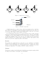
2.1
2.2
2.3
Stepper motor operation . . . . . . . . . . . . . . . . . . . . . . . . . . .
Extruder components . . . . . . . . . . . . . . . . . . . . . . . . . . . . .
Mbed microcontroller . . . . . . . . . . . . . . . . . . . . . . . . . . . . .
15
15
18
3.1
3.2
3.3
High-level diagram of overall system architecture. . . . . . . . . . . . . .
G-code processing pipeline . . . . . . . . . . . . . . . . . . . . . . . . . .
Stepper controller board with connections labelled (photo [Rep12g]) . . .
20
21
23
4.1
4.2
4.3
4.4
24
25
26
4.7
4.8
4.9
4.10
4.11
4.12
4.13
4.14
4.15
4.16
4.17
4.18
4.19
4.20
4.21
Components of the main board . . . . . . . . . . . . . . . . . . . . . . .
Electronics installed with key components labelled . . . . . . . . . . . . .
Types of prototyping board . . . . . . . . . . . . . . . . . . . . . . . . .
Top-level layout of main board (reset button and power connections not
shown) . . . . . . . . . . . . . . . . . . . . . . . . . . . . . . . . . . . . .
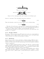
Metal Oxide Semiconductor Field Effect Transistor (MOSFET) . . . . .
IRLU8729PbF Typical Transfer Characteristics (reproduced from ‘Fig 3’,
[Int09]) . . . . . . . . . . . . . . . . . . . . . . . . . . . . . . . . . . . . .
Example MOSFET circuit with pull-down resistor . . . . . . . . . . . . .
Potential divider . . . . . . . . . . . . . . . . . . . . . . . . . . . . . . .
Photo-interrupter with a photo-transistor in a Darlington pair . . . . . .
Photo-interrupter endstop being interrupted by the X-axis . . . . . . . .
X-ray of RJ45 sockets with and without integrated magnetics [Lom12] . .
Successive-approximation analog-to-digital converter . . . . . . . . . . . .
PID heater controller schematic . . . . . . . . . . . . . . . . . . . . . . .
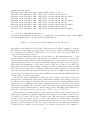
Stepper control signal wave diagram . . . . . . . . . . . . . . . . . . . . .
Nyquist-Shannon sampling theorem example with high-frequency signal .
Example of sampling artefacts . . . . . . . . . . . . . . . . . . . . . . . .
Mbed timer architecture . . . . . . . . . . . . . . . . . . . . . . . . . . .
UDP G-code Sender Datagram Format . . . . . . . . . . . . . . . . . . .
makebed live.sh screen shot . . . . . . . . . . . . . . . . . . . . . . . .
Emergency stop/reset button . . . . . . . . . . . . . . . . . . . . . . . .
Breadboard with a prototype end-stop circuit . . . . . . . . . . . . . . .
5.1
Ping responses being duplicated by the µIP driver . . . . . . . . . . . . .
4.5
4.6
7
26
27
27
28
29
29
30
31
32
33
34
35
35
36
39
40
41
42
46
5.2
5.3
5.4
5.5
5.6
5.7
Exponential back-off by computer when µIP flow-control used . . . . . .
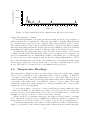
Checking platform temperatures using an infra-red thermometer . . . . .
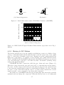
Synthetic 3D printer tests for basic calibration . . . . . . . . . . . . . . .
Bad print of the test in figure 5.4(D) . . . . . . . . . . . . . . . . . . . .
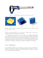
Digital callipers being used to measure test cuboids . . . . . . . . . . . .
Test cuboid model (A) print from Skeinforge G-code before raft removal
(B) and after raft removal (C) . . . . . . . . . . . . . . . . . . . . . . . .
5.8 3D printed vase with detailed corners . . . . . . . . . . . . . . . . . . . .
5.9 3D printed Z-axis handle comparison . . . . . . . . . . . . . . . . . . . .
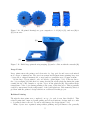
5.10 3D printed herringbone gear comparison . . . . . . . . . . . . . . . . . .
5.11 Failed large print showing warping (A) and a collision with the extruder (B)
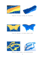
5.12 Folding ‘butterfly comb’, printed without a raft . . . . . . . . . . . . . .
53
54
54
55
55
56
A.1
A.2
A.3
A.4
A.5
A.6
A.7
A.8
A.9
.
.
.
.
.
.
.
.
.
65
66
66
67
68
68
69
69
70
Flexible snake to test printing many thin fins . . . . . . . . . . . . . . . .
Starfish to test layering appearance . . . . . . . . . . . . . . . . . . . . .
Doorstop to test large, smooth gradients . . . . . . . . . . . . . . . . . .
Butterfly to test intricate islands of print . . . . . . . . . . . . . . . . . .
Rabbit outline to test very thin structures . . . . . . . . . . . . . . . . .
Letter ‘A’ to test simple large shapes . . . . . . . . . . . . . . . . . . . .
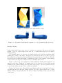
Phone stand to test steep gradients . . . . . . . . . . . . . . . . . . . . .
Tooth to test large models with large overhanging areas . . . . . . . . . .
Multiple ‘metabricks’ to test building batches of objects . . . . . . . . . .
Twistable heart to test simple mechanisms and multi-part objects . . . .
Whistle (with pea printed inside) to test precise, air-tight objects with
simultaneously printed sub-components . . . . . . . . . . . . . . . . . . .
B.12 Tweezers to test flexible designs (frequently used to remove excess extrusion produced during self-cleaning) . . . . . . . . . . . . . . . . . . . . .
71
71
72
72
72
73
73
73
74
74
OpenSCAD showing a cube model compiled and rendered . .
ReplicatorG GUI showing a cube model loaded . . . . . . . .
Skeinforge profile selection dialogue . . . . . . . . . . . . . . .
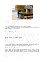
Extruder placed in the homing bracket . . . . . . . . . . . . .
Extruder extruding plastic during a self-clean . . . . . . . . .
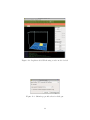
First layer being printed . . . . . . . . . . . . . . . . . . . . .
Fill pattern being printed . . . . . . . . . . . . . . . . . . . .
Finished cuboid being ejected . . . . . . . . . . . . . . . . . .
Strings of plastic left during printing requiring manual removal
.
.
.
.
.
.
.
.
.
.
.
.
.
.
.
.
.
.
.
.
.
.
.
.
.
.
.
.
.
.
.
.
.
.
.
.
.
.
.
.
.
.
.
.
.
B.1
B.2
B.3
B.4
B.5
B.6
B.7
B.8
B.9
B.10
B.11
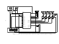
C.1 Main board circuit diagram (direct connections to stepper controllers omitted for clarity) . . . . . . . . . . . . . . . . . . . . . . . . . . . . . . . . .
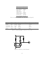
C.2 End-stop circuit schematic . . . . . . . . . . . . . . . . . . . . . . . . . .
8
47
48
52
52
53
74
75
78
80
List of Tables
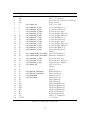
4.1
4.2
20-pin ATX Connector Signals[Int04] . . . . . . . . . . . . . . . . . . . .
Stepper timing constraints . . . . . . . . . . . . . . . . . . . . . . . . . .
30
34
5.1
Generic PID controller constants for a Makerbot [Ind12c] . . . . . . . . .
49
C.1 Mbed pin connections . . . . . . . . . . . . . . . . . . . . . . . . . . . .
C.2 End-stop interface cat-5 wire allocations [Rep12d] . . . . . . . . . . . . .
C.3 Opto-interrupter connection colour codes . . . . . . . . . . . . . . . . . .
77
80
80
D.1 G-code register types and behaviours . . . . . . . . . . . . . . . . . . . .
82
E.1 Key source file listing . . . . . . . . . . . . . . . . . . . . . . . . . . . . .
E.2 Firmware software dependencies . . . . . . . . . . . . . . . . . . . . . . .
E.3 Utility dependencies . . . . . . . . . . . . . . . . . . . . . . . . . . . . .
91
91
92
F.1 Network interface ports . . . . . . . . . . . . . . . . . . . . . . . . . . . .
F.2 Status interface commands and responses . . . . . . . . . . . . . . . . . .
94
96
9
Chapter 1
Introduction
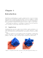
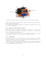
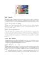
3D printing is a manufacturing process where computer models of objects are automatically reproduced in a physical form [JE12]. Figure 1.1 shows an example of a complex
3D printed object. Various 3D printing technologies exist, some of which have gained a
number of hobbyist-friendly implementations. In this project, a number of refinements to
the popular Makerbot Cupcake CNC 3D printer were made to improve its performance.
In this chapter the applications of 3D printing are examined followed by an introduction to the Makerbot and the improvements made by this project.
1.1
Applications
3D printing technologies allow complex objects, including complete mechanisms, to be
easily manufactured based on digitized designs in one go with a single piece of equipment. Various materials are used including metal, various plastics, resins and even sugar
[Can12].
Rapid prototyping is an obvious application where the flexibility to quickly manufacture a wide range of objects extremely valuable. For example, Boeing are using 3D
printing to reduce the tooling cost and speed up prototyping its aeroplanes [Sta12].
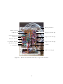
Figure 1.1: 3D printed ‘Gear Cube’ produced by the printer upgraded in this project
10
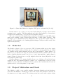
Figure 1.2: Unmodified Makerbot Cupcake CNC (photo by Rayshobby [Pro12])
Because there is no tooling cost associated with changing a design, custom manufacturing is also possible. This has applications both for personalised goods and more
recently in the manufacture of bespoke medical implants [Mar12].
The cost of entry-level 3D printers has recently become much lower with DIY devices
such as the RepRap costing between $300 and $620 to build [She12, Rep12f]. This
has helped grow communities such as Thingiverse where people share their designs for
printable objects with the goal of making physical things as easily accessible as any other
digital media [Ind12d].
1.2
Makerbot
The Makerbot (figure 1.2) is an open source, DIY 3D printer which can produce plastic
objects up to 10cm × 10cm × 13cm in size. It consists of a moving platform onto which
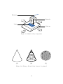
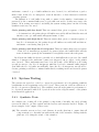
an ‘extruder’ melts plastic filament and deposits a thin strand of plastic (figure 1.3).
Objects are produced by moving the platform underneath the extruder and to form
layers of plastic which are stacked one on top of each other until the complete shape is
formed. Figure 1.4 shows how a cone (A) might be sliced into layers (B) and how each
layer might be printed (C).
Software running on a computer handles the process of slicing a 3D model and generating the list of movements required to print it out. A simple microcontroller on the
Makerbot receives this list of instructions and generates the carefully timed electronic
signals needed to drive the printer’s components.
1.3
Project Motivation and Goals
The Makerbot, while a very capable machine, has many limitations in its hardware,
electronics and firmware. In this project the control electronics and microcontroller are
the primary area for improvement. The existing system has trouble with complex designs
11
Filament
Extruder
Print
Platform
Figure 1.3: Makerbot key components
(A)
(B)
(C)
Figure 1.4: Slicing a 3D model into layers to be printed
12
where dense sequences of instructions exceed the microcontroller’s limited resources and
slow serial interface. The electronics are also a complicated configuration of several
circuit boards using crude mechanical relays. Finally, the printer does not have sensors to
indicate the positions of the platform and extruder requiring the platform to be carefully
positioned before prints. This is a time consuming and error prone task which also means
that the printer can’t detect mechanical errors during printing.
In this project, each of these three complaints are addressed by the following primary
project goals:
Simplify control electronics Produce a single board which contains all required components using only reliable solid-state parts.
Improve performance Upgrade to a more powerful microcontroller and develop new
firmware to exploit the resulting improvements in speed and communications capabilities.
Add sensors for platform and extruder movements End-stop sensors at the end
of each axis of movement will be added to allow the system to position itself.
1.4
Report Outline
This report first discusses the background of the project covering 3D printing and the
technologies selected for the project. In chapter 3 the design of system is proposed followed by details of the implementation in chapter 4. Chapter 5 describes how the system
was tested and evaluates the new system’s performance. Finally, chapter 6 concludes the
report and describes opportunities for future work following on from the project.
13
Chapter 2
Background
In this chapter the background of the project is described. The principle components
of the Makerbot are discussed in more detail followed by a description of the tasks carried out by the firmware required to drive them. Afterwards, the ARM based ‘Mbed’
microcontroller used in this project is introduced along with the ‘FreeRTOS’ operating
system.
2.1
Makerbot
The Makerbot Cupcake CNC used in this project is the first generation of a series of
printers based on the RepRap 3D printer [Ind12a]. The RepRap, and consequently the
Makerbot are open designs which are freely available for use and modification.
In this section, the primary components of the printer are described followed by the
electronics, firmware and microcontroller that drives them.
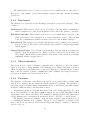
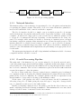
2.1.1
Printer Components
The printer can be broken down into three major components, the axes along which the
machine’s components can move, the extruder which melts the plastic and the platform
itself on which the design forms. Each of these are described below.
Axes of Movement
There are three axes of movement in the Makerbot. Two horizontal axes along which the
platform can travel, the X- and Y-axes, and one vertical axis along which the extruder
is moved, the Z-axis.
The X and Y axes move along rails and are belt driven by a stepper motor. The
Z-axis moves up and down four threaded rods which are connected together via a belt
and driven by a single stepper motor. When the threaded rods turn, the extruder is
moved by the screwing effect of the rods.
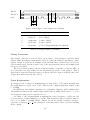
Stepper motors allow precise movements to be made. In contrast with simple DC motors which turn electrical energy into continuous movement, stepper motors turn energy
into discrete ‘steps’ of movement.
14
0°
3.75°
1
7.5°
2
3
11.25°
4
Figure 2.1: Stepper motor operation
Filament
DC Motor
Heater
Nozzle
Extrusion
Figure 2.2: Extruder components
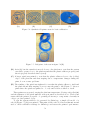
A simple stepper motor consists of four toothed electromagnets and a toothed magnetic central rotor. By turning on each electromagnet in sequence, the teeth of the rotor
are moved to align with the energised electromagnet causing a single step of movement
to be executed (an example is given in figure 2.1) [Inc12].
By controlling these steps, the motor’s rotation and speed can be exactly controlled.
Stepper motors lack active feedback mechanisms and rely solely on the motor successfully
completing every step. This assumption does not hold if the motor is unable to provide
enough torque (turning power) to move its load. As a result, the motors used by the
printer are designed to be powerful enough to reliably provide the torque required so that
sensors are not needed to judge the position of the system.
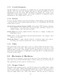
Extruder
The extruder uses a simple DC motor and gearbox to force a filament of acrylonitrile
R
butadiene styrene (ABS) plastic, the material from which Lego
is made, into a heater
and out of a fine nozzle (figure 2.2). A temperature sensor is installed in the heater
allowing the temperature to be carefully controlled to ensure an even flow.
Platform
The platform contains a heated build surface which helps prevent prints warping and this
also improves the adhesion of the print to the build surface.
15
The build surface is also a conveyor belt powered by a small DC motor and gearbox.
It is used to eject printed objects after printing completes allowing continuous printing
operations.
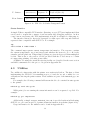
2.1.2
Electronics
The Makerbot is controlled by the RepRap’s generation 3 electronics [Rep12c]. These
consist of:
Motherboard This circuit board hosts an 8-bit microcontroller which communicates
with a computer via a custom serial interface and controls the printer’s operation.
Extruder Controller This circuit board hosts a second small microcontroller along
with electronics for the extruder’s motor and temperature sensor. The extruder
controller communicates with the motherboard via a custom RS485 interface.
Relay Board This circuit board contains a mechanical relay for turning each of the two
heaters on and off. The relay board is driven by the extruder controller using simple
digital signals.
Stepper Motor Driver (×3) Circuit boards which produce the high-power signals required to drive the stepper motors. These boards are connected to the motherboard
via a simple digital interface that abstracts away many of the electrical and timing
difficulties driving a stepper motor.
2.1.3
Microcontrollers
The electronics use a pair of Arduino-compatible microcontrollers to drive the printer.
These devices have a fairly minimal 8-bit instruction set, limited amounts of memory
(4KB of RAM) and a very limited set of options for high-speed communications. A faster
microcontroller capable of faster communication and command processing is needed to
solve the performance problems described in §1.3.
2.1.4
Firmware
The firmware on the microcontrollers is responsible for two main tasks: receiving print
data from a computer and producing the signals required for printing. The signals produced have strict ‘real-time’ timing requirements and so to meet these, specialised timing
hardware within the microcontroller must be used.
3D printers typically receive print data in the form of G-code files [Rep12b]. G-code is
the de facto standard for controlling computer numerical control (CNC) machines such as
3D printers, laser cutters and lathes. The language is human readable and defines stepby-step instructions for machine actions such as ‘move to (X,Y,Z)’ or ‘enable heater’.
The RepRap generation 3 firmware on the motherboard uses a custom serial protocol
to communicate with the host computer. This protocol is designed to be simple for the
microcontroller to use and, as well as various diagnostic features, contains a compressed
version of G-code.
16
2.1.5
G-Code
G-code is assumed to execute on an abstract ‘G-code machine’. The machine consists of
26 numeric registers named ‘A’ to ‘Z’. A G-code instruction consists of a set of register
assignments after which the machine executes a specific action based on the contents of
its registers.
Some registers may be reset to an ‘undefined’ state before each instruction allowing
the machine to identify when a register is written. For example, the ‘G’ and ‘M’ registers
are used to specify what type of action should occur and, if not cleared, it would be
impossible to determine which register contains the action required.
Each register accepts either a floating point or integer value, for example the ‘G’ and
‘M’ registers only accept integer action numbers while ‘X’, ‘Y’ and ‘Z’ are floating point
and accept coordinates.
For example, when the instruction G1 X10 Y-15 Z0.3 F3000 is encountered, the following register values are set:
F: 3000
G: 1
X: 10
Y: −15
Z: 0.3
In this example, the action is ‘move to’ as determined by the ‘G’ register. The ‘X’,
‘Y’ and ‘Z’ registers determine where to move and ‘F’ determines the speed. If this is
followed by M104 S225 then the following registers will be set:
F: 3000
M: 104
S: 225
X: 10
Y: −15
Z: 0.3
Note that the ‘G’ register has been undefined but the others have remained. In
this example, the action is determined based on the ‘M’ register to be ‘set extruder
temperature’ and the ‘S’ register determines the temperature. ‘X’, ‘Y’, ‘Z’ and ‘F’ are
ignored. Finally, if G1 Z0.6 is encountered the following registers are set:
F: 3000
G: 1
S: 225
X: 10
Y: −15
Z: 0.6
Once again the machine determines the action to be ‘move to’ and moves to the
position defined by ‘X’, ‘Y’ and ‘Z’ at the speed in ‘F’, ignoring the ‘S’ register. Because
the values of ‘X’ and ‘Y’ have not been changed, the machine will move only the Z-axis.
2.1.6
Support Software
The G-code used by the printer is generated from 3D models using an open-source tool
called Skeinforge [ske12]. Skeinforge is typically used as part of ReplicatorG, a graphical
user interface for preparing and printing 3D models [rep12a]. ReplicatorG can also handle
the translation of G-code into the compressed format used by the RepRap firmware.
Other less mature tools, such as Slic3r, are available but less frequently used.
2.2
ARM & Mbed
As well as high-performance processors designed for phones, ARM also design the CortexM series of microcontrollers. For this project a Cortex-M3 based ‘Mbed’ microcontroller
was chosen to replace the pair of existing 8-bit microcontrollers [Sem12b]. The reasons
for the suitability of this choice are justified in this section.
17
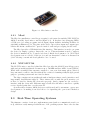
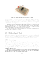
Figure 2.3: Mbed microcontroller
2.2.1
Mbed
The Mbed is a small microcontroller prototyping board centred around the NXP LPC1768,
ARM Cortex-M3 based microcontroller (figure 2.3). It has has four debugging LEDs,
a USB port for loading programs various input/output facilities including facilities for
attaching an Ethernet port. The pins on the device expose these input and output capabilities and fit into standard 0.1” spaced circuit boards and prototyping breadboards.
The Mbed provides a USB flash drive-like interface. This interface is used to program
the device by simply copying a binary file onto it. This mechanism is used to support
the device’s unusual choice of purely web-based official development tools. Web-based
development was not ideal for this project and an alternative solution is discussed in
§4.2.1 allowing conventional development tools to be used.
2.2.2
NXP LPC1768
The LPC1768 microcontroller behind the Mbed provides the ARM Cortex-M3 processor
with various useful peripherals. It runs at up to 100MHz and has 32KB of ram [NXP10].
While still a seemingly tiny amount compared to even a modest smart phone, this is a
large amount for a microcontroller without the overhead of running a fully-fledged general
purpose operating system and associated software.
The chip contains various peripherals such as hardware timers, analog interfaces and,
importantly, fast Ethernet support. These timers will, as with the previous microcontrollers, be vital for driving the electronics properly. Analog inputs are also needed to
interface with the electronics. Ethernet support will allow the microcontroller to quickly
receive detailed print data over the network.
As well as these features, ARM devices are widely used and boast mature, open-source
development tools making it an ideal choice for expanding the open-source Makerbot
design.
2.3
Real-Time Operating Systems
The firmware consists of various complementary parts (such as communication and control), which are easily managed with the use of an operating system. Due to the absolute
18
timing and performance requirements FreeRTOS, a real-time operating system (RTOS),
was selected.
2.3.1
Differences With Non-Real-Time Systems
Real-time operating systems, like other operating systems, provide a scheduler which
allows multiple processes to run as if simultaneously. It also provides facilities for communicating between these processes. Unlike regular operating systems, an RTOS can
provide exact timing guarantees. They are also generally targeted at microcontroller development with tight resource constraints and without the need for extra hardware such
as a memory management unit (MMU).
2.3.2
FreeRTOS
FreeRTOS is a widely used, open-source RTOS designed for use with a range of microcontrollers, including many Cortex-M3 based devices [fre12]. The two key features provided
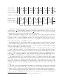
by FreeRTOS are ‘tasks’ and ‘queues’ which are described below.
Tasks
A system built on FreeRTOS can be structured as several tasks executing in parallel.
Tasks are similar to processes or threads on a conventional operating system with each
task having its own set of registers and a stack.
Because the microcontroller can only run one task at once, the FreeRTOS uses preemptive scheduling to approximate this behaviour where the current task is periodically
interrupted by a timer (preempted) and a different task put in its place. If tasks are
switched fast enough, they appear to run simultaneously.
Tasks may be given different priorities and can be suspended until events such as
a timer expiring or a hardware resource becoming available occur. The timing of the
operating system’s actions can be guaranteed allowing real-time systems to be developed.
Queues & Mutexes
To provide synchronisation and communication between tasks, FreeRTOS provides a
queue structure. Queues are defined which allow data to be inserted or removed with a
first-in-first-out (FIFO) access scheme.
These queues can be used safely by multiple tasks simultaneously without race conditions and so are ideal for inter-task communication. Because of this safety, they also
form the basis for standard parallel programming constructions such as semaphores and
mutexes.
When accessing a FreeRTOS queue a task may become blocked, for example, when
adding an item to a queue that is already full. FreeRTOS can provide timing guarantees
on timeouts waiting for these functions to complete. It also allows a task’s priority to be
temporarily raised when resumed after a blocking call, ensuring it is scheduled as soon
as possible, reducing the delay before any new data is processed.
19
Chapter 3
Design
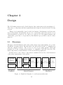
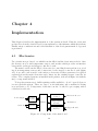
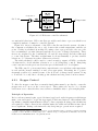
The 3D Printing system can be divided up into three main parts as shown in figure 3.1.
These major components and their requirements and design are described in the following
sections.
This project is principally focused on the development of the firmware and electronics
used by the printer. In particular, the process of generating 3D models and G-code as
well as mechanical operation is out of the scope of the project. The printer hardware and
off-the-shelf, open source tools provided by the Makerbot project will be used for these
purposes.
3.1
Firmware
The microcontroller firmware will consist of three main components running on top of the
FreeRTOS operating system. The first will be the µIP network stack for communication
with the computer software. The second, is a G-code processing pipeline which will
translate G-code into an appropriate sequence of commands to drive the electronics. The
third component is a driver interface for the various Mbed peripherals.
In this section, each of these components is examined followed by a brief discussion
of the safety requirements of the system.
3D Modeling/
G-Code
Generation
Status
Monitoring
Computer
G-Code
Interpreter
Printer
Controller
Network
Interface
I/O
Drivers
Control
Electronics
Printer
Hardware
Status
Monitor
Mbed Firmware
Hardware
Figure 3.1: High-level diagram of overall system architecture.
20
Network
G-Code
Buffer
G-Code
Interpreter
Command
Buffer
Printer
Controller
Hardware
Figure 3.2: G-code processing pipeline
3.1.1
Network Interface
The firmware will provide an interface for streaming G-code to the printer and an interface
for querying the printer’s status. This will be done via a network interface primarily to
increase the bandwidth of the connection with the computer.
The G-code interface should be a simple open port which accepts G-code streams
and feeds them into the pipeline without the need for specialised software on the sending
computer. It will need to support flow control as the rate at which the printer is able
to accept G-code instructions will vary depending on what instructions are being executed. For example, while waiting for heaters to warm up, no instructions are executed
but during complex movements, many instructions are executed in rapid secession. The
interface must also be reliable because a missed, corrupted or out-of-order G-code instruction would cause potentially dangerous results. TCP offers both reliable communication
and flow control mechanisms and is implemented in µIP making it an appropriate choice
for this task1 .
The status querying interface should be kept minimal and human readable. A telnet
compatible interface should be created.
3.1.2
G-code Processing Pipeline
The main task of the firmware is to process incoming G-code from the network and to
control the printer appropriately without stalling. A pipeline architecture (figure 3.2) was
selected where G-code from the network is buffered before being interpreted and converted
into low-level commands. The low-level commands are placed in another buffer and then
executed in sequence to drive the printer.
In order to reduce stalls due to data processing between commands, space is exchanged
for computation time by keeping all command arguments in formats directly used by the
printer in the low-level commands. For example, distances should be represented as an
integral number of steps and not floating point millimetre values.
At the start of the pipeline, the effect of network latency should be minimised by
allocating a large G-code buffer giving the network longer to respond to changes in the
rate of command execution before the buffer drains.
Finally, by assigning a high priority to the printer controller the delay between a command completing and another starting is minimised. This minimises the error introduced
during very short bursts of extremely detailed movements.
1
Some G-code implementations have error checking and retransmission mechanisms built in but these
are poorly specified and designed for use with serial connections.
21
3.1.3
G-code Interpreter
Though existing G-code interpreters are available they are generally tightly integrated
with the control logic they were designed with and not easily used standalone. G-code
implementations also vary widely with 3D printers but generally only a require a very
small subset of the language features. As a result, a small G-code interpreter will be
implemented for the required subset of G-code.
3.1.4
Drivers
In order to interface with the electronics and facilitate accurate timing, various peripherals
on the Mbed will be used requiring supporting driver code. In particular, the following
features will be needed:
General-Purpose Input/Output (GPIO) Allows digital, TTL (Transistor-TransferLevel), signals to be produced and read from the pins on the microcontroller. For
example, stepper control and end-stop signals.
Analog Input Read analog signals from the electronics, for example, readings from
temperature sensors.
Timer Used to produce interrupts at precisely timed intervals to allow stepper control
signals to be generated.
Watch-dog Timer To ensure fail-safe behaviour, a watch-dog timer can be used to
reset and power down the system in the event of software malfunction.
3.1.5
Safety
The system must behave safely in the event of a software failure and should be interruptible by a user at any time. The system must also start up in a safe state so that
unintentionally powering on the machine cannot result in dangerous behaviour. Readings from the system must also be sufficiently accurate that they do not mislead the user
about the system’s safety.
3.2
Electronics & Hardware
New electronics are required to replace the motherboard, relay and extruder boards. As
well as this, electronics and hardware must be added for the proposed end-stop sensors.
The requirements for these parts are described below.
3.2.1
Stepper Control
The printer’s three primary axes are controlled by stepper motors which require complex
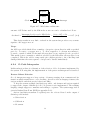
circuitry to drive them. Off-the-shelf RepRap stepper motor drivers (figure 3.3) will be
used as in the existing electronics [Rep12h]. The boards connect to the stepper motor
and power supply and provide a TTL control interface. They also provide a connection
22
Power
Stepper Motor
End-stops
TTL Interface
Figure 3.3: Stepper controller board with connections labelled (photo [Rep12g])
for two end-stop sensors to be attached (the output from which they passively forward
back through the TTL interface).
The enable, direction and step signals from each stepper board must be driven by the
microcontroller’s GPIO pins.
3.2.2
Heater & DC Motor Control
The heaters and motors both require large amounts of current at 12 volts to run. This
far exceeds the output capabilities of the GPIO pins on the Mbed so a circuit will be
needed to switch the power for these devices.
Previously, mechanical relays were used to control the heaters but instead a solid-state
solution should be sought to allow the possibility of varying heater power.
3.2.3
End-stops
By adding end-stop sensors on each axis, the axes can be accurately and consistently
positioned at the start of a print job. Electronics compatible with the interface exposed
by the stepper controller board will be required.
Optical end-stops have been selected as the Makerbot has pre-drilled mounting holes
at the end of each axis for mounting them. Optical end-stops are also non-contact and
so do not disrupt the movement of the axes.
23
Chapter 4
Implementation
This chapter describes the implementation of the system in detail. First the electronics
produced are described and followed by an explanation of the firmware which drives them.
Finally, safety considerations and a brief discussion of the development methodology used
is presented.
4.1
Electronics
Two circuits were produced, one which hosts the Mbed and the electronics needed to drive
the heaters, motors and temperature sensors and another which provides an interface
between the end-stops and stepper controller boards.
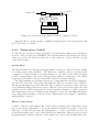
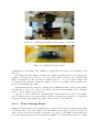
The main board hosts the Mbed, electronics for controlling heaters and motors, reading from temperature sensors and connections for the stepper controller boards (figure
4.1). A second board is used for the end-stop electronics as these parts may be replaced
separately from the main electronics and connect via the existing stepper controller interface. The completed system, as installed in the printer, is shown in figure 4.2 with the
major components labelled.
To keep the system easy to build requiring readily available tools, 0.1” spaced electronics were used throughout. These are easy to work with using only a standard soldering
iron and basic tools. Components of this size can also be used for prototyping with a
solderless breadboard.
Power Supply
Heater & Motor
Control
Power
Control
Temperature
Reading
Mbed
Network
Heaters & Motors
Thermistors
Ethernet
Stepper
Interface
Stepper Boards
Figure 4.1: Components of the main board
24
End-stop Interface
End-stop Board
Stepper Controller (Z)
To End-stops
To Heaters/Motors
Stepper Controller (Y)
Main Board
Ethernet Interface
Programmer Interface
Stepper Controller (X)
Stop/Reset Button
To PSU
To Thermistors
ATX Power Supply
Figure 4.2: Electronics installed with key components labelled
25
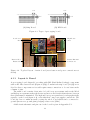
0.1"
0.1"
0.1"
0.1"
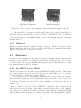
(A) Strip Board
(B) DIP Board
Figure 4.3: Types of prototyping board
Low-Power
Area
High-Power
Area
Passive External
Connections
Reserved For
Future Use
Figure 4.4: Top-level layout of main board (reset button and power connections not
shown)
4.1.1
Layout & Board
A prototyping board designed for working with DIP (Dual In-line Package) components
such as the Mbed was selected (Figure 4.3(B)). Conventional strip board (4.3(A)) is not
ideal for these components as it would require many connections to be cut between the
columns of pins.
The main board contains electronics for both low-power systems such as the Mbed
and high-power systems such as the heater and motors and electrical interference between
these parts must be minimised. The high and lower power parts have been kept physically
separate on the board (figure 4.4), each with their own power supply connections. The
board also has a continuous track covering the whole board which can be connected to
ground (known as a ground plane), helping reduce noise [Sil06].
A full circuit schematic and pin-out for the board is given in Appendix C.1.
26
Drain
Gate
Gate
Source
Source
Drain
(A) Physical Appearence
(B) Symbol
Figure 4.5: Metal Oxide Semiconductor Field Effect Transistor (MOSFET)
Drain-to-Source Current (A)
1000
100
10
1
Drain-to-Source
Voltage = 15V
0.1
1
2
3
4
5
6
7
8
Gate-to-Source Voltage (V)
Figure 4.6: IRLU8729PbF Typical Transfer Characteristics (reproduced from ‘Fig 3’,
[Int09])
4.1.2
Heaters & DC Motors
The heaters and DC motors in the extruder and platform operate at a higher voltage
and are considerably higher-current than the microcontroller can provide on its output
pins. To control these a transistor can be used. Transistors act like a switch which allows
high-power components to be switched on and off using only a small current from the
Mbed. An IRLU8729PbF MOSFET (Metal Oxide Field Effect Transistor) was selected
as it can switch large loads up to 58A with very little on-resistance (reducing energy
wastage through heat) [Int09].
A MOSFET has three connections called the gate, drain and source (Figure 4.5).
When the voltage between the gate and source is 0V, no current flows from the drain to
the source. As the voltage between the gate and drain are increased, the current allowed
to flow increases rapidly when it passes a certain threshold (Figure 4.6). By connecting
the gate to a pin on the Mbed and the source to ground, a large current from a device
such as a heater or motor attached to the drain can be switched.
The behaviour of a MOSFET when the gate is left floating (disconnected) is generally
undefined and can damage the component. When the Mbed powers on, its output pins
27
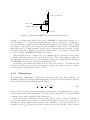
+12V
Load (e.g. Heater)
Mbed Pin
Pull-Down Resistor
Ground
Figure 4.7: Example MOSFET circuit with pull-down resistor
default to a floating state which could cause a MOSFET to unexpectedly switch on or
become damaged. To prevent this happening the gate is connected to ground via a
resistor. When the output pin is floating the gate is pulled to 0V by the resistor. When
the output of the pin is not floating, the gate is pulled to that voltage overriding the
pull-down resistor. A high resistance value is used so that the Mbed can easily override
the pull-down resistor. Figure 4.7 shows the circuit used to control the two heaters and
two motors using a MOSFET and pull-down resistor.
When driving motors, a ‘flyback diode’ is usually used to prevent a voltage spike
occurring when the power is removed from the motor. This voltage spike is caused by
the magnetic field in the motor’s coils collapsing. This is not included in the circuit as
the MOSFETs used already contain an appropriate diode.
It should be noted that this circuit does not allow the motors to be driven in both
directions as this is not needed by the printer. If this was required, a more complex
circuit (such as an H bridge) would be needed.
4.1.3
Thermistors
To measure the temperature of the heaters, thermistors are used. The resistance of a
thermistor changes non-linearly with temperature and can be modelled using an equation
derived from the Steinhart-Hart Equation [SH68]:
1
1
R
1
=
+ ln
T
T0 β
R0
(4.1)
Where T and R are the current temperature and resistance of the thermistor, T0 and R0
are the temperature and resistance at a reference temperature and β is a characteristic
constant for the device available in the data-sheet.
Using the Analog-to-Digital converter in the Mbed, voltages, but not resistances,
can be read directly. As a result, a potential divider (figure 4.8) is used to produce a
measurable voltage which is proportional to the resistance to measure it indirectly. A
reference voltage Vref is placed across two resistors, R1 and R2 , and the voltage between
28
V
R1
R2
Vref
Figure 4.8: Potential divider
Photo-transistor
Infra-Red LED
Figure 4.9: Photo-interrupter with a photo-transistor in a Darlington pair
them at V is measured. The relationship between these variables is
R2
V = Vref
R1 + R2
(4.2)
Thus, if the thermistor is placed as R2 , the resistance can be calculated using
R1
R2 = Vref
(4.3)
V − Vref
The value of R1 was chosen to evenly spread the voltages from the expected range of
thermistor resistances over the full range of 0 to Vref volts. This maximises the utilisation
of the analog to digital converter available over the temperature ranges used.
Using (4.1) and (4.3) with a potential divider circuit will allow the temperature of the
thermistor to be measured.
4.1.4
Stepper Motors
The stepper controllers chosen accept TTL signals and connect via a ten-pin insulation
displacement connector (IDC). An IDC socket was placed on the board and the pins
connected directly to the Mbed and ground plane as required.
4.1.5
End-stops
Optical end-stops consist of a photo-interrupter containing an infra-red LED and a phototransistor arranged across a gap (Figure 4.9). Photons from the LED activate the phototransistor allowing current to flow but, when the gap is blocked, the transistor is switched
off and no current flows.
Due to problems sourcing the interface boards for the end-stops, a circuit was built
which is compatible with the stepper-controller interface. +5V and ground are provided
and a TTL logic signal is expected by the interface. To ease debugging, an indicator LED
was also added which is lit when the end-stop is unobstructed.
The LED in the photo-interrupter is driven via a current-limiting resistor and the
signal output and indicator LED are connected through the photo-transistor. A pulldown resistor is used to pull the signal to ground when the photo-transistor is powered
off.
29
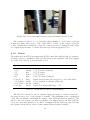
Figure 4.10: Photo-interrupter endstop being interrupted by the X-axis
The circuitry is placed on a board with cables running to each end-stop (shown
mounted in figure 4.10) and to each of the CAT-5 sockets on the stepper controller
boards. Strain-relief is included so that the connections are not damaged if the cables
are caught in the machine. A circuit diagram is provided in appendix C.2.2.
4.1.6
Power
The printer uses an ATX power supply unit (PSU) commonly found in desktop computers.
A 20-pin connector containing both power and various control signals for the power supply
(see table 4.1) is used to power the main board.
Signal
Colour
Notes
Ground
+3.3V
+5V
+12V
-12V
Black
Orange
Red
Yellow
Blue
±5% Tolerance (Unused)
±5% Tolerance
±5% Tolerance
±10% Tolerance (Unused)
Power Good
Gray
+5V Standby Purple
+3.3V Sense Brown
Power On
Green
Signal asserted when all voltages are correct and stable
Power available at all times (Max 2A)
Unused
Active-Low signal pulled up to +5V
Table 4.1: 20-pin ATX Connector Signals[Int04]
The Mbed is connected to the 5V standby supply allowing it to remain connected to
the network and power on the system on demand. The maximum power consumption
of the Mbed is 200mA, well within the ratings of the ATX specification [Sem12b]. The
Mbed’s on-board regulator provides a regulated 3.3V supply used by the Mbed and the
low-power electronics attached to it. The 3.3V supply from the PSU is not used because
the regulator in the Mbed offers a cleaner supply which is always available.
30
(A) Without Magnetics
(B) With Magnetics
Figure 4.11: X-ray of RJ45 sockets with and without integrated magnetics [Lom12]
To allow the PSU to be turned on by the Mbed, the power on signal is attached to a
GPIO pin. Because the Mbed is a 3.3V logic device a MOSFET is used to connect the
5V Power On signal to ground (thus turning on the Power Supply) using the 3.3V signal
from the Mbed.
4.1.7
Ethernet
Ethernet requires relatively complex circuitry to drive it. With the exception of the
Ethernet magnetics, this is provided on-board the Mbed. A jack containing the magnetics
(figure 4.11) was used to complete the system.
4.2
Firmware
In this section the firmware for the Mbed is described, starting with the infrastructure
required for development on FreeRTOS on the Mbed and then moving on to the major components of the system. Finally the safety precautions taken and the tools and
development practices used are outlined.
4.2.1
FreeRTOS on the Mbed
The Mbed is designed for use with a web-based IDE and compiler [Sem12a]. This system
is not appropriate for use in the project as the process of uploading code to be compiled
is laborious and the compilation options restricted.
The CodeSourcery G++ None-EABI toolchain includes a GCC ARM cross-compiler,
linker and LibC compiled for various ARM based microcontrollers. It was selected over
closed-source alternatives because it has a large community of users and produces good
quality code.
An unofficial port of FreeRTOS for the Mbed is available designed for the CodeSourcery toolchain. It provides a base FreeRTOS configuration with a demonstration
µIP based web server as well as other simple operating system demos. Also included
are headers for the ARM Cortex Microcontroller Software Interface Standard (CMSIS)
which defines a common interface for ARM Cortex microcontrollers [ARM12]. Finally,
headers defining macros and pointers for all control registers in the Mbed are included.
31
Analog-In
Hold
+
Comparator
-
Digital-to-Analog
...
Register
Control Logic
Figure 4.12: Successive-approximation analog-to-digital converter
Appendix E.2.2 contains specific compilation instructions for the final system with
the CodeSourcery toolchain.
4.2.2
Temperature Control
To drive the two heaters an active-feedback loop is used where input from a thermistor
is used to drive a heater via a MOSFET. The following subsections describe how analog
values are read by the Mbed and the theory and operation of the feedback loop that
controls the heaters.
Analog Input
The Mbed includes a 12-bit successive-approximation analog-to-digital converter (ADC)
for reading analog values [NXP10]. The ADC uses a digital-to-analog converter and a
comparator to binary search for an approximation to the analog value while the input
is held constant (figure 4.12). Once an appropriate number of iterations of the binary
search have been carried out, the value in the register is returned [Max01].
The ADC sampling process takes at least 5µs or approximately 500 CPU cycles therefore the CPU can carry out another task while the ADC process takes place [NXP10].
Though an interrupt is provided when the ADC completes (as well as a direct memory
access (DMA) facility), this was not used. Instead, a slow-poll is used where the task
reading from the ADC is suspended for a time typically adequate for ADC operation.
The temperature sensors are sampled at an extremely low rate (around 2Hz) and latency
is not important as changes occur very slowly. This system is very simple to implement
with negligible overhead.
Heater Control Loop
A naı̈ve controller could simply turn on the heaters whenever the temperature drops
below some target temperature or ‘set point’ and then off when it was met or exceeded.
This type of controller can cause the temperature to overshoot and fall below the set
point as the heating and cooling of the system is not immediate. Instead a proportionalintegral-derivative (PID) controller is used which can control heaters which takes into
32
Comparator
Set Point
+
Heater
-
Temperature
Figure 4.13: PID heater controller schematic
account such behaviours. PID controllers are widely used where a process which is not
completely understood must be controlled [Ben93].
Figure 4.13 shows a schematic of the PID controller used in the system. At time t
the comparator calculates the error, e(t), between the actual temperature and the set
point. A value is calculated from this error using a factor proportional to the error, the
error accumulated over time (integral) and the error’s rate of change (derivative). These
factors are weighted by the constants Kp , Ki and Kd respectively and the result used
to control the heater. The three weights must be chosen manually to produce sensible
behaviour. §5.5 discusses how these values were selected.
The value calculated could be used to control an analog output or PWM1 or a threshold value used to decide whether a heater is on or off (‘bang-bang’ control). Bang-bang
control was used as the previous electronics proved this method to be adequate.
The PID control loop is executed in its own task twice a second when each temperature
is read and the heaters switched on and off as appropriate. Executing the loop more
frequently would not be useful because of the slow rate of change in the system. Doing
so would also be costly due to floating point calculations being carried out in software.
4.2.3
Stepper Control
To drive the stepper controllers, accurately timed pulses must be produced to cause the
stepper motors to move at the correct speed. These pulses also need to be coherent
between motors so that the three axes can move simultaneously to plot straight paths.
Principle of Operation
Before each movement begins, a periodic timer is set based on the frequency at which steps
must occur and is used to toggle the step signal. This is used instead of Bresenham’s line
algorithm to simplify implementation [Bre65]. Since expensive floating point calculations
are required for value conversion into machine units, the additional calculation introduced
is not significant. During each timer tick only cheap integer operations are required.
1
Pulse width modulation (PWM) is a method of approximating analog outputs by rapidly switching
a signal on and off with a varying duty-cycle. This is cheap to implement in hardware and avoids
inefficiencies in MOSFETs when only partially driven.
33
Enable
Direction
Forward
Backward
Step
Figure 4.14: Stepper control signal wave diagram
Period
Meaning
Timing Constraint
tsh
tsl
Step high
Step low
≥ 1µs [All09]
≥ 1µs [All09]
ts
th
Setup time
Hold time
≥ 200ns [All09]
≥ 200ns [All09]
tt
Step time
≥ 757µs (Experimentally determined)
Table 4.2: Stepper timing constraints
Timing Constraints
The stepper controller boards are based on an Allegro A3982 stepper controller which
defines additional timing requirements. Table 4.2 gives the timing constraints for these
signals. Figure 4.14 shows an example waveform with three forward steps followed by
four backward steps. On the positive edge of the step signal the direction is sampled and
the motor is stepped.
The motors in the printer add an additional timing constraint, tt , due the limit on
how often they can step defined by the mechanical properties of the printer. This is
important because the faster the stepper is driven, the less torque is available and so the
stepper may miss steps and fail to move.
Timer Requirements
If a stepper is set to run at its maximum speed, steps will be 757µs apart meaning that
the signal must be toggled every 379µs. Therefore the output signals may change at up
to 1.32kHz.
FreeRTOS provides timing guarantees for scheduling arbitrary delays within tasks.
Unfortunately, this uses the system timer which ticks at 1kHz which is far too low for
the frequencies such as those discussed above.
According to the Nyquist-Shannon sampling theorem a frequency of f Hz can only
be generated by a timer running at > 2f Hz. This means the timer resolution must be
above 2 × 1.32kHz = 2.64kHz [Sha49]. Figure 4.15 shows ‘aliasing’ caused by trying to
reproduce a signal at 23 (> 12 ) the frequency of the timer where whole cycles are missing
in the output.
34
Timer Clock
Desired Signal
Generated Signal
Figure 4.15: Nyquist-Shannon sampling theorem example with high-frequency signal
Sample Clock
Desired Signal
Generated Signal
Figure 4.16: Example of sampling artefacts
The effect of sampling artefacts can cause further inaccuracies. Figure 4.16 shows
a signal below 12 of the sampling frequency displaying such artefacts. In the worst case
when sampling at f Hz, a signal change may be f1 s late. Therefore, increasing the sampling
frequency decreases the error introduced by such artefacts.
High print quality depends on smooth, even steps, as a result, the timer resolution
must be not only above 2.64kHz due to the Nyquist-Shannon sampling theorem but also
be high enough to reduce sampling artefacts to an acceptable level. If errors due to
artefacts are to be reduced in the worst case to, for example, one-hundredth of the step
period then a frequency of 264kHz is needed.
Increasing the speed of the system timer to such a frequency would make the overhead
of the scheduler unacceptable and so the FreeRTOS timer cannot be used. Instead a
hardware timer which interrupts the microcontroller causing a light weight interrupt
service routine (ISR) to run will be needed.
Because the Mbed only provides a limited number of hardware timers, just one is used
to control all three steppers. As each stepper may not be in phase, the time between
signals being produced for each stepper can become very small, even when the step period
is large. This is another example of a sampling artefact where the resulting errors are
at worst f1 s for a timer running at f Hz. Because the timer is already sufficiently fast to
make such errors insignificant, no extra precision is required when sharing a timer.
The timers provided on board the Mbed consist of a register comparator and counter
which is incremented by the system clock after being passed through a clock divider (figure
4.17). The timer was configured such that when the counter matches the value in the
register, the counter is reset and the CPU is interrupted. The timer was configured to run
at 1MHz which exceeds the 264kHz requirement calculated above with some additional
margin.
The ISR for the timer interrupt determines for each stepper, whether its step signal
should be toggled and calculates how long until another interrupt is required. The timer
compare register is updated, the ISR returns and normal program execution resumes.
GCC generates approximately 100 instructions for the ISR taking an estimated 250
cycles to execute2 . Assuming the CPU executes one instruction per cycle at 100MHz the
2
Estimate based on informal analysis of the generated assembly code
35
Register
Counter
Clock
Reset
Interrupt
Figure 4.17: Mbed timer architecture
amount of CPU time used by the ISR in the worst case can be calculated as follows:
Overhead =
(1.32 × 10³ ) × 250
Interrupts Per Seccond × ISR Cycles
=
= 0.33% (4.4)
Cycles Per Seccond
100 × 106
This design results in very little overhead in the system but provides very accurate
signals to the stepper motors.
Usage
An API is provided which allows a number of steps in a given direction with a specified
period to be sent to a stepper motor. To allow sequences of coherent movements to
be made, a method which blocks until all steps have been completed is also provided.
This method uses a semaphore which is released by the ISR when all steps have been
completed. This is also used to temporarily give a higher priority to the controlling task
during which time the next sequence of steps can be started immediately.
4.2.4
G-Code Interpreter
In this subsection there is a discussion of the selection of G-code features implemented by
the system. Following this, the implementation of the parser and interpreter is described.
Feature Subset Selection
G-code interpreters support a large variety of features ranging from comments and instructions which return data to error checking. As well as various language features, the
actions available and their precise behaviours differ.
To keep the system as simple (and fast) as possible, only features and actions required
to support the output of Skeinforge’s G-code generator were implemented. The resulting
language simply supports comments and writing to registers. The syntax supported is
given in Backus-Naur Form (BNF) in appendix D.1.1.
Actions (and their treatment of registers) were also selected based on the output of
Skeinforge and include:
• Unit selection
• Calibration
• Movement
36
• Motor control
• Power control
• Temperature control
• Delays
A complete description of the actions supported is given in appendix D.2.
Parsing
The G-code subset supported is very simple and so a small parser was implemented by
hand rather than using a standard parser generator such as GNU Bison. Such tools
also generate code that is not optimised for running on a microcontroller in a real-time
environment and would have been time consuming to learn.
A simple state machine was built which parses and executes the G-code setting and
reading registers as described in §2.1.5. When unexpected characters or register values are
encountered a flag is set and the parser continues from the next character or instruction.
Once each instruction is parsed and the register values set, the values are converted
into machine units. For example, movements are converted into relative movements
measured in stepper motor steps and speeds converted into step periods measured in
timer ticks. These low-level commands are then added to the command buffer to be
executed by the printer controller.
4.2.5
Printer Controller
The printer controller uses a FreeRTOS queue in a high priority task to buffer low-level
commands from the G-code interpreter. The controller consists of a simple loop which
executes each command requiring minimal processing. As a result, this task spends most
of its time blocked waiting for actions to complete but responds quickly when required.
4.2.6
Network Interface
The network interface consists of two services built on the µIP stack: a G-code transmission interface and a status monitoring interface. µIP provides a simple API for sending
and receiving data over TCP and UDP within applications built within its protosocket
and protothread frameworks [Dun06].
Protothreads are extremely lightweight threads using cooperative multitasking implemented in pure C. These threads do not preserve registers or variables during blocking
phases of execution and use minimal system resources. Protosockets are a simplified
UNIX-style socket interface built on protothreads. These libraries are designed with extremely low-power microcontrollers in mind. As a result, only a minimal application is
implemented within the µIP framework which passes data from the network immediately
to the other parts of the system.
The G-code was initially implemented using TCP but a bug in µIP’s flow control
implementation meant an alternative implementation was required and built on UDP.
The two protocols are outlined below along with an additional TCP interface used for
reporting the system’s status.
37
TCP G-code Interface
The TCP G-code interface consists of an open port listening for connections. Once
connected a client simply sends the G-code to the printer and disconnects when finished.
Telnet or net-cat (nc) can be used to send G-code files to the printer, for example
nc 192.168.3.100 1818 -q 0 < model.gcode
Where model.gcode is the file to send and 193.168.3.100 is the IP of the printer.
As the G-code subset supported does not support return values, nothing is returned
by the printer.
UDP G-code Interface
Unfortunately, as discussed in §5.3, the TCP implementation in µIP is incorrect. Due
to time constraints this was not fixed during the project. Instead a UDP based protocol
was implemented.
UDP provides a facility for sending datagrams containing a small amount of data to a
remote host. These datagrams are not guaranteed to arrive or to arrive in the order they
are sent. They do include a checksum and so if a datagram arrives it can be safely be
assumed to be intact. Finally no flow-control mechanism is provided (excess packets are
silently dropped). They are, however, lightweight and a good base for building custom
protocols.
UDP alone cannot be used to send data to the printer and simple protocol has been
built on top which provides a communications channel which is
• Reliable
• Unidirectional
• Order-guaranteed
• Flow-controlled
Figure 4.18 shows the format of datagrams sent between the printer and sender.
Datagrams are sent to the printer which contain a sequence number and a payload whose
length can be calculated based on the datagram’s size (contained in the UDP header). The
sender then waits for a response from the printer containing the same sequence number
and a window size. The printer will only respond if a datagram with an appropriate
sequence number is received discarding out-of-order datagrams. If a response with a
matching sequence number is not received by the sender within a short timeout, the
datagram is retransmitted. This mechanism facilitates reliable, in-order transmission.
The window size returned by the printer is used for flow control and is the amount of
space in the G-code buffer or the maximum datagram size (whichever is smallest). The
sender may send up to this amount of data to the printer in its next datagram ensuring
the printer is always sent as much data is it can deal with. If the G-code buffer becomes
full then the window size will become zero the sender must poll the printer until the
window size becomes non-zero.
§5.3 discusses the performance and practical implications of this protocol and the full
specification is given in Appendix F.1.
38
To Printer:
(UDP Header)
Sequence No.
Payload (G-code)
From Printer:
(UDP Header)
Sequence No.
Window Size
Figure 4.18: UDP G-code Sender Datagram Format
Status Interface
A simple Telnet-compatible TCP interface (listening on port 2777) was implemented that
can be used to request the contents of various status and debugging variables. As flow
control was not necessary, the TCP implementation in µIP is adequate for this purpose.
The interface listens for keywords separated by white space and responds with tab
separated data compatible with GNU Plot. For example:
tmp
22523 22500 0 11800 12000 1
The command tmp requests current temperature information. The response contains
the current temperature, set point (target) and whether the heater is on or off for the
extruder and the platform. Temperature readings are given in degrees Celsius multiplied
by 100. This is due to the version of LibC provided with the CodeSourcery tool chain
not supporting printing of floating point values.
A utilities for using the status monitoring facility are described in the next section
and full documentation for the protocol is given in Appendix F.2.
4.3
Utilities
Two utilities for interacting with the printer were written in Python. The first, a client
implementing the UDP G-code transmission protocol and, the second, a utility for conveniently monitoring the printer status. These utilities are part of the makebed.py command.
For example, the following command will stream the G-code contained in cube.gcode
to the printer:
makebed.py send cube.gcode
While print jobs are running the status information can be requested or polled. For
example:
makebed.py get temperature
Additionally, a simple wrapper, makebed_live.sh, is provided written in Bash using
GNU Plot to plot various pieces of printer status information in real-time (figure 4.19).
Usage information for the utilities can be found in Appendix E.3.
39
Figure 4.19: makebed live.sh screen shot
40
Figure 4.20: Emergency stop/reset button
4.4
Safety
Because the system contains heaters and moving parts, safety was a major consideration
when implementing the system. This section outlines the key features used to ensure
operation is as safe as possible including human-interaction features and fail-safe design.
4.4.1
Heater Indicator LEDs
The two heaters each use an indicator LED on the microcontroller to indicate when the
heaters are powered on. This enables an operator to easily and safely check the state of
the heaters during operation.
4.4.2
Power-on Behaviour
On power-on, the PSU is not turned on and so the heaters and motors do not receive
power. The only way to start the heaters is to open a new connection to the printer and
send the required PSU and heater instructions. This design means that if the printer is
powered on unintentionally it will not do anything unsafe. It also means that resetting
the printer has the effect of putting it into a safe state where an explicit action is required
to restart it.
4.4.3
Stop Button
The electronics connect the Mbed’s reset pin to a larger and easier to press red button
(figure 4.20). Because of the safe power-on behaviour and indifference to software failures
this button can always put the system into a safe state.
4.4.4
Watchdog Timer
The most safety critical software process is that of the heater controller. If this routine
fails for any reason the heaters may become stuck powered on. As over-heating is not as
obvious to the operator as for example, a jammed axis, this is a particularly dangerous
fault.
To catch such faults the Mbed includes a hardware watchdog timer (WDT). The
WDT contains timer which, upon timing out, resets the system. The WDT must be ‘fed’
41
Figure 4.21: Breadboard with a prototype end-stop circuit
(reset) periodically to prevent it resetting the system. To feed the WDT specific values
must be loaded in the correct order into a control register. This mechanism can catch
bugs which cause the routine to jump to a random location, block for an excessive period
or otherwise become corrupted.
The heater controller loop executes at 2Hz and the WDT is fed at the end of each
iteration of the control loop. The WDT is set with a timeout of two seconds meaning
that it should never come close to a timeout except in the event of a control loop has
failure or the system resources have somehow become saturated.
After the WDT has reset the system it enters a safe state where the heaters do not
have power and are allowed to cool safely.
4.5
Methodology & Tools
In this section the methodologies used for the implementation of the system are discussed
followed by the choice of languages and development tools and why they were selected.
Finally the methods used to debug the firmware running on the Mbed are described.
4.5.1
Methodology
Development followed an iterative, bottom-up process where components were built,
tested and then integrated into the system as a whole.
Prototyping was used heavily in the development of the electronics. The major parts
of the circuit were initially prototyped on a solderless breadboard and powered by a
bench power supply (figure 4.21). In these prototypes, different components could easily
be swapped in and out of the design and measurements easily taken with the system
running at different voltages.
The UDP protocol was also initially prototyped using a high level language (Python)
allowing quick development and testing. Some parts of the prototype were subsequently
modified and used as part of the off-printer client software.
42
4.5.2
Languages
The firmware was written entirely in C. As well as a mature compiler and manufacturerprovided header files, C strikes a good balance between the availability of sensible abstractions and providing low-level access to the underlying hardware. Thanks to a policy of
manual, static memory management no garbage collection or dynamic memory allocation
was required which helps make system performance more deterministic.
The off-printer utilities are written primarily in Python and include a wrapper shell
script written in Bash. These languages provide very high levels of abstraction simplifying
and accelerating development. The performance costs incurred by using such languages
are not relevant on a modern PC for the simple tasks required and so represent a good
fit for the project.
4.5.3
Version Control
To track changes and keep snapshots of the project’s code, Git was used for version
control [git12]. Git provides facilities for quickly comparing versions of code. It also
allows experimental copies or branches of the code base to be created and independently
modified. Useful changes can be made in their own isolated branches and easily be merged
back into the main version of the system. Changes can also be quickly reverted. These
features allowed new ideas to be created and tested without fear of irreversibly altering
the system.
4.5.4
Debugging
Microcontrollers are typically debugged using a JTAG (Joint Test Action Group) interface
which allows the microcontroller to be paused, stepped and examined during program
execution. Unfortunately the Mbed does not expose this interface and so all debugging
must be carried out through the input/output facilities provided.
The port of FreeRTOS used included a demonstration web server which was modified
during the first iteration of firmware development to allow program variables to be exposed through this interface. Eventually the demonstration code was removed and the
status interface described in §4.2.6 was put in its place providing equivalent facilities.
Both interfaces allowed internal variables to be polled, examined and graphed on a PC.
As well as the firmware itself, its interactions with the network also required debugging. To do this Wireshark, a network analyser was used. This allows the individual
packets sent and received by a computer to be monitored, filtered and examined. It
also includes protocol specific features such as protocol checking and protocol-specific
statistics.
43
Chapter 5
Testing & Evaluation
As the system was built, the individual parts were unit-tested extensively before integration into the rest of the system. Integration tests were then performed followed finally
by a series of full system tests. This strategy meant testing was a continuous process
throughout the implementation and identified bugs early.
In this chapter the tests carried out during development are described along with an
evaluation of the results. Each section describes the tests a major component of the system was subjected to concluding with an evaluation of the system’s overall performance.
5.1
Electronics
The major components of the electronics were prototyped and tested on a breadboard
with the use of a multimeter. The higher power components, such as the heaters and
motors, were initially disconnected or tested with low-power test loads until the circuit
was deemed to be correct. Once connected, these components were then tested under
operational loads with careful supervision to ensure that they functioned correctly and
that the current flowing through each part of the circuit was as expected. The tested
circuit designs were then soldered together on circuit boards where the connections were
first tested for continuity and checked for short circuits before performing integration
tests on the system.
Overall the electronics performed well and no problems caused by electrical noise
generated when switching high-power loads were observed. The parts of the system which
were found to exhibit unexpected behaviour are outlined in the following subsections.
5.1.1
MOSFETs
The MOSFETs were able to switch on the heaters and bring the system from room
temperature to operating temperature within 10 minutes, matching the performance of
the previous system as expected.
After an extended period of being powered on, the MOSFETs became hot running at
around 50◦ C. The data sheet for the IRLU8729PbF MOSFETs states that the operating
temperature range is from −55◦ C to 175◦ C and so this temperature is safely within
operational limits.
44
5.1.2
End-stops
Printed plastic paddles were originally planned as the triggers for use with the end-stops.
Unfortunately, acrylonitrile butadiene styrene (ABS) plastic used by the Makerbot is
transparent to the infra-red wavelengths used by the opto-interrupters and so this material
is unsuitable. The design was changed to instead use wooden craft ‘lollipop sticks’ which
fit into pre-cut slots in the Makerbot and easily trigger the opto-interrupters.
5.1.3
ATX PSU
Some ATX PSUs require a certain load on all provided voltages in order to power up
properly [Rep12e]. While a large load is drawn on the 12V line by the heaters and motors,
the 5V line only powers the Mbed which draws little power. The result of this is that
the 12V line attached to the heaters only provided 9V and so could not warm up to the
required temperature.
A resistor can be added to the 5V line to draw extra current and fully power up
the PSU [Rep12e]. Due to time constraints an alternative PSU was used which did not
feature this behaviour rather than modifying the circuit. With the new PSU, all voltages
met their specified requirements.
5.2
FreeRTOS
The availability of the FreeRTOS port made it extremely easy to integrate into the
project. FreeRTOS itself provided the right balance of features and performance for the
project. The operating system did not place restrictions on the use of low-level system
registers and simply provided preemptive multitasking and some atomic operations as
required.
The operating system was initially tested for timing accuracy using a frequency probe
attached to an I/O pin toggled by a simple demonstration program to ensure the system
was behaving as expected. This test yielded a mismatch from the expected frequency
which was found to be an incorrect definition of the system clock speed in a FreeRTOS
header file. Once fixed the system ran as expected running the included demo and test
programs as defined. No further issues were found during the course of the project.
5.3
µIP & Networking
Various tests were conducted on the µIP stack during the project, concentrating on
performance and correctness of the features used. This section discusses these tests and
concludes with an evaluation of µIP’s suitability for the project.
Wireshark was used to monitor the packets sent between the Mbed and computer
where it became apparent that every packet from the Mbed was being duplicated. After
ruling out network problems as the cause, the bug was traced down to the Ethernet driver
provided by the demo. The driver duplicated every packet sent to the network (including
IMCP Ping Requests, figure 5.1). As well as wasting bandwidth, if a TCP packet acknowledgement (ACK) from the Mbed was to be delayed in the network, retransmission
45
$ ping 192.168.3.100
PING 192.168.3.100 (192.168.3.100) 56(84) bytes of data.
64 bytes from 192.168.3.100: icmp_req=1 ttl=64 time=0.364 ms
64 bytes from 192.168.3.100: icmp_req=1 ttl=64 time=0.385 ms (DUP!)
64 bytes from 192.168.3.100: icmp_req=2 ttl=64 time=0.175 ms
64 bytes from 192.168.3.100: icmp_req=2 ttl=64 time=0.195 ms (DUP!)
64 bytes from 192.168.3.100: icmp_req=3 ttl=64 time=0.195 ms
64 bytes from 192.168.3.100: icmp_req=3 ttl=64 time=0.212 ms (DUP!)
64 bytes from 192.168.3.100: icmp_req=4 ttl=64 time=0.179 ms
64 bytes from 192.168.3.100: icmp_req=4 ttl=64 time=0.195 ms (DUP!)
^C
--- 192.168.3.100 ping statistics --4 packets transmitted, 4 received, +4 duplicates, 0% packet loss, time 3000ms
rtt min/avg/max/mdev = 0.175/0.237/0.385/0.081 ms
Figure 5.1: Ping responses being duplicated by the µIP driver
will result in four duplicate ACK packets. This causes the sending computer to retransmit and incorrectly adjust its expectations of the network connection when the packets
are eventually received [Sch12]. This behaviour is one factor that can prevent TCP flow
control from functioning correctly.
The packet duplication behaviour is often added to µIP implementations to work
around problems caused by µIP only allowing one packet to be sent at a time [Mai].
Modern systems (such as Windows and Linux) will allow several packets to arrive before
acknowledging them all at once, saving bandwidth reducing the effect of network latency.
This delays the transmission of the next packet by µIP as it waits for the ACK. By
duplicating each packet, the receiving computer is forced to immediately send an ACK
as, from receiver’s perspective, a duplicate packet may indicate that the original packet
was delayed in the network and the sender did not receive an ACK in time in this case
because the receiver had never sent it. As a result the receiver sends the ACK immediately
allowing µIP to send the next packet.
Though this wastes bandwidth it reduces the wait between each packet being sent
and in practice dramatically increases the bandwidth available when sending data from
the Mbed to the computer. Disabling this work-around means sending multiple-packet
bursts of data to a computer is more time consuming but removes a barrier to flow control
being used successfully. The only data sent from the Mbed are status responses which
are small enough (around 30 bytes) to fit in a single packet. Disabling packet duplication,
in favour of removing a barrier to proper flow control, is a good trade off.
Unfortunately, problems with flow control persisted with no improvement after disabling packet duplication. With the duplicate packets removed, the traffic became clearer.
To enable flow control, TCP sends a window size with each packet representing the
amount of data the receiver is able to receive. µIP reports a constant window size until
the method uip_stop() is called when the window size is set to zero and any further
packets received are discarded. The zero window message is resent until uip_restart()
is called and the old window size is restored. A packet is then sent to the computer to
46
Transferred (B/s)
20000
10000
0
120
140
160
180
200
220
Time (s)
Figure 5.2: Exponential back-off by computer when µIP flow-control used
request data transfer to continue.
To test this mechanism, a program was written which produced a long sequence of
small movement G-code instructions. This causes the buffer to initially fill up and then
be constantly kept topped up by the computer while being restrained by flow control.
The actual behaviour of the connection (shown in figure 5.2) shows the buffer is initially
filled (the first spike) but then the sender waits an exponentially growing period until it
starts filling the buffer again regardless of when the window size is made non-zero.
By inspecting the packets sent and received, the window size is always obeyed by the
computer but the packet announcing the window size becoming non-zero appears to be
ignored as transmission is not immediately resumed. Wireshark’s protocol checker did
not report any errors and comparison with the known-working implementation of TCP
flow control in Linux did not reveal any obvious differences. Unfortunately further study
did not yield a diagnosis for the problem. Due to the time constraints imposed by the
project TCP had to be dropped for G-code transmission in the project.
5.4
Temperature Readings
The temperature readings depended on correct values being read from the analog inputs
and on correct calculation of the temperature based on these readings. Consistency
of readings is important, reading temperatures close to the actual value, however, is
relatively unimportant. This is because the temperature is fairly uneven within the heated
components of the printer and so it is difficult to define a ‘correct’ reading. The actual
temperature values used during printing are calibrated manually and so the absolute
temperature in ◦ C is not significant.
To test analog input, a selection of resistors with known values within the range
of values the thermistor could exhibit were tested. As well as breadboard testing, the
test was repeated on the final circuit board as the screw terminal used to connect the
thermistors could also be used to connect a test resistor directly.
When converted to a resistance using (4.3), the values read were found to be within
±2% of the resistor value as read by a multimeter (a difference which is accounted for by
the fact that a second resistor with a ±5% tolerance is used in the potential divider).
To test that temperatures were being correctly calculated, an infra-red thermometer
(figure 5.3) was used to take reference temperature readings from the extruder and plat47
Figure 5.3: Checking platform temperatures using an infra-red thermometer
form. The heaters were turned on and readings were taken every minute as the extruder
and platform heated up and then every five minutes for half an hour as it cooled down.
The tests were repeated multiple times alongside other experiments, each time with similar results, to ensure consistency. These values were then compared against the value
calculated using (4.1).
The radius of the area measured by the thermometer becomes larger as it is moved
further away from the target. Because the temperature across the platform and extruder
vary greatly depending on location, the thermometer was placed close to the centre of
the extruder nozzle and the centre of the build platform where the thermistors reside.
The temperatures recorded for the extruder were within ±1◦ C below 100◦ C but rose
to around +8 ± 1◦ C around 220◦ C (normal operating temperature).
The platform temperatures were initially incorrect by ±10◦ C or more. This was
caused by a simple connection error. Once the problem was corrected, readings followed
a similar pattern to the extruder (up to the 125◦ C the platform is designed to operate
at).
The results above represent adequate performance for the task of maintaining a desired
temperature and also show that the temperatures read are close to their real values such
that an operator can safely tell from a temperature reading that the device is unsafe
to touch. The error at high temperatures may be a result of not being able to use the
thermometer to measure the internal parts of the extruder where it is hottest.
5.5
PID Control
The PID controller has three constants (Kp , Ki and Kd ) which must be manually tuned
to yield sensible system performance. An optimal system has oscillations in temperature
that are as small as possible.
PID controller tuning is a non-trivial problem for which automated solutions are either
highly specialised or unavailable. Heuristics exist such as The Ziegler-Nichols method for
selecting good values which work in many cases and require human interpretation [ZN42].
48
Constant
Extruder Value
Platform Value
Kp
Ki
Kd
5.143
0.0612
108.0
7.0
0.342
36.0
Table 5.1: Generic PID controller constants for a Makerbot [Ind12c]
The Makerbot wiki suggests values (given in table 5.1) which yield adequate performance on many printers [Ind12c]. After selecting these values the printer’s performance
was monitored both while idle and during printing and the size of the oscillations were
measured. Performance was similar in both states (with the exception of a temperature
jump in platform temperature at the start of printing caused by molten plastic being extruded on top of the thermistor). Oscillations were ±2◦ C for the extruder and platform.
Due to time constraints, further improvements in tuning could not be achieved. Though
this is greater than the ±1◦ C recommended, print quality was not adversely affected.
5.6
Stepper Control
The amount of plastic deposited at a given point during a print is dependent on the
rate at which the plastic is extruded and also the rate at which the platform moves.
The accuracy of the timing (combined with the mechanical properties of the machine)
determines the platform’s rate of movement and thus the print quality.
The stepper control system consists of code for producing accurately timed steps and
code for coherently moving the stepper motors. These two parts were tested separately
as described in the following subsections.
5.6.1
Timing
To ensure timing accuracy, the three stepper signals were driven at a combination of
frequencies with a frequency probe attached to the step pin. These tests were generated
initially using a program on the microcontroller (so that the system was not under any
load) and then using G-code sent over the network interface while other requests were
being made (to place the system under reasonable load).
The frequencies measured were exact to within the accuracy of the probe (four significant figures) for all tests.
5.6.2
Stepping
To test that steps happened coherently, with sequences of steps correctly spaced apart,
the system was connected to the printer and circles were plotted. The circles are made up
of short, continuous line segments where the relationship between the movements on each
axis varies. Once again, the test was initially conducted using a test program running on
the Mbed and then by G-code sent over the network. The number of segments the circle
was divided into was increased from 30 to 3, 000 and the speed set to 330mm/minute and
3300mm/minute to test slow and fast movements.
49
The performance of the system was measured by visual inspection of the movement
and circles plotted by attaching a pen to the extruder. The time taken the plot the
circles was also measured using a timer on the Mbed to see if the processing overhead
between each segment caused significant drift. Above around 100 segments the circles
drawn appeared smooth and at low and high speeds the overhead after 20 circles had
been plotted at each speed and resolution was less than the 1ms resolution of the timer.
Finally, to ensure that steps were not missed, the system was moved to a known point
between tests and this did not drift after all tests had completed.
5.7
End-stops
The endstops were tested under various lighting conditions to observe the effect of external
lighting on the opto-interrupters. The following lightings conditions were tested:
• Ambient strip lighting
• Ambient halogen lighting
• Ambient incandescent lighting
• Ambient natural light
• Direct halogen lighting
• Direct incandescent lighting
• Darkened room
Testing consisted of blocking each opto-interrupter by moving the printer axes so that
the end-stop is triggered and observing the digital value read by the Mbed and the state
of the debugging LED. Under all but the direct lighting conditions the correct value was
read and the debugging LEDs were either completely off or completely on. Under direct
lighting, especially incandescent lighting, the state read by the Mbed for some end-stops
became stuck due to external light shining into the opto-interrupters. In these cases the
debugging LEDs did not become completely ‘off’ indicating that the opto-interrupter was
being only partially triggered.
Though these results suggest that the end-stops cannot be used under direct lighting
from halogen or incandescent bulbs, the system was found to perform well outside these
conditions. Although not tested due to unfavourable weather conditions, direct natural
light may also have caused similar problems. While these restrictions are unfortunate,
they are not unreasonable and still allow the system to be used in practice.
5.8
Buffer Utilisation
To ensure that the printer pipeline did not stall during print jobs, the G-code and lowlevel command buffers were monitored during the execution of various test jobs. If buffer
50
underruns occurred or poor buffer utilisation was observed, it could indicate a performance issue in the G-code interpreter, network interface or their interaction with the
operating system.
The utilisation of each buffer along with a counter for the number of underruns experienced by the command-buffer were logged while various G-code files were sent to the
printer. Most testing was carried out during the system testing phase but the following
synthetic tests were also used.
Circle plotting with low detail This test ensured that, given a sequence of slow Gcode instructions, the printer keeps all buffers reasonably full and that the network
interface can cope with small, infrequent bursts of data.
Circle plotting with high detail This test ensures that, given a constant sequence of
fast G-code instructions, the printer keeps all buffers reasonably full and that no
underruns occur during busy periods.
Circle plotting with high detail and pauses This test ensures that given a sequence
of fast G-code instructions separated by pauses (where the buffers filled and the
network interface paused) the transmission can quickly restart after the pause.
In all tests the buffer levels were generally above half full in the worst case. In a small
number of instances the underrun counter was triggered but no effect on the printer
was observed. These underruns may have been the result of FreeRTOS not allocating
enough resources to the G-code interpreter until the low-level command buffer emptied
(but while the G-code buffer was still full). Once the G-code interpreter was allowed to
execute, printing would have continued immediately resulting in the unobservable pauses
observed.
5.9
System Testing
The system was tested as a whole to assess its performance in both printing synthetic
benchmarks as well as printing real-world objects. These tests also aided in calibration of
the G-code generator (Skeinforge). The synthetic tests allow the printer’s performance to
be objectively measured while real objects show the real-world performance of the printer
in its intended application.
5.9.1
Synthetic Tests
As a simple test of using all of the printer’s components coherently, the circle plotting
test was modified to produce spirals and the heaters and extruder enabled. Figure 5.4
shows samples of the output of these tests:
(A) The extruder was moved at a safe distance from the platform to ensure that all
components move coherently but without the risk of the extruder colliding with the
platform or blocking the nozzle of the extruder.
51
(A)
(B)
(C)
(D)
Figure 5.4: Synthetic 3D printer tests for basic calibration
Figure 5.5: Bad print of the test in figure 5.4(D)
(B) As in (A) but the extruder is moved closer to the platform to test that the system
can safely operate close to the platform and that the plastic adheres properly (and
then is properly detached when ejected).
(C) A larger spiral was printed to test that the plastic adheres closer to the (colder)
edges of the platform and that warping due to temperature changes during the
print, does not cause problems.
(D) The winding of the spiral was tightened to test that the plastic adheres to itself and
the platform and that warping does not cause the print to fail. Figure 5.5 shows a
print where the spiral was printed too loosely and it did not adhere to itself.
These prints were repeated, varying the platform temperature, Z-axis position (height)
and the tightness of the spiral until the tests performed as described above. These tests
ensure that the printer is capable of operating all its major components coherently in
order to produce printed object.
To test the system with G-code generated by Skeinforge, a simple 3D model of a
cuboid (Figure 5.7 (A)) was printed. This print yields a cuboid of known dimensions and
used to check calibration settings for Skeinforge and assess the printer’s performance.
52
Figure 5.6: Digital callipers being used to measure test cuboids
(A)
(B)
(C)
Figure 5.7: Test cuboid model (A) print from Skeinforge G-code before raft removal (B)
and after raft removal (C)
The cuboid was initially printed on top of a thick ‘raft’ of plastic (used to ensure an even
printing surface) and then separated using a chisel.
The dimensions of the cuboids were checked using a pair of digital callipers (figure
5.6) to ensure that the printed object is of the correct size. The Makerbot wiki claims
that 0.1mm resolution is possible on a correctly tuned machine and this requirement was
met by most of the printed cuboids [Ind12b]. In a small number of cases, the Z-axis of
the printer did not move the required amount due to the mechanism jamming, a known
problem with the Makerbot design [Jet12]. As a result, these prints were of the incorrect
height but were otherwise correct and the problems not attributed to the firmware.
5.9.2
Test Objects
To test the printer’s ability to produce useful objects, various objects were printed including objects with moving parts or near the print size limits of the printer. These tests
check the system’s ability to deal with large and complex loads. A selection of printed
test objects is provided in Appendix B.
53
Figure 5.8: 3D printed vase with detailed corners
(A)
(B)
Figure 5.9: 3D printed Z-axis handle comparison of old (A) and new (B) electronics
Detailed Prints
Prints with detailed areas were used to test that the system could process the larger
density of G-code at the required rate and also to ensure that steps were not missed
during printing.
For example, figure 5.8 shows a vase which yields very short line segments while
printing the corners of the shape. The previous electronics would not be able to process
this design fast enough and would skip instructions causing steps to be missed. With the
new electronics no buffer underruns or printing problems occurred during a run featuring
a large version (shown) and a smaller version containing finer detail.
Figure 5.9 shows an object which has a small cylindrical handle printed with the old
and new electronics. With the old system, the G-code was not processed fast enough
resulting in the printer stalling and depositing extra plastic. The new system was able
to process the same amount of G-code without stalling.
Figure 5.10 shows a pair of herringbone gears printed with the old and new electronics.
(A) and (B) show how the new system is able to produce rounder circles due to better
timing accuracy. (C) and (D) show the effect of improved timing accuracy on the teeth
of the gears.
54
(A)
(B)
(C)
(D)
Figure 5.10: 3D printed herringbone gear comparison of old (A) & (C), and new (B) &
(D) electronics
(B)
(A)
Figure 5.11: Failed large print showing warping (A) and a collision with the extruder (B)
Large Prints
Large prints stress the printer and electronics for long periods and can reveal missed
motor steps or instructions. The previous system had frequent issues printing large test
objects due to skipped instructions or steps and is a particular area for improvement.
Of the large objects printed, only one failed to print (figure 5.11). This was due to
the object warping (A) and then becoming detached from the platform during the print
causing the tip of the extruder to rip the object off the platform (B). Unevenness in the
temperature of the object during printing is the cause of this distortion. This is partially
caused by unevenness in the temperature of the build platform. Unfortunately, this is a
problem with the printer’s design which is not addressed in this project.
Raftless Printing
Though the first prints were completed on top of a raft, it was later disabled. This
reduced print time, improved print quality and allowed intricate designs such as combs
to be printed where removal of a raft would damage the design (figure 5.12).
Many objects were reprinted using raftless printing and performance was generally
55
Figure 5.12: Folding ‘butterfly comb’, printed without a raft
similar with the exception of larger designs. These experienced greater warping without
the support of the raft and thus were more prone to failure due to the extruder hitting
the object.
56
Chapter 6
Conclusions & Future Work
In this chapter, the outcomes of the project are compared against the initial goals and
future work is suggested based on lessons learnt and the limitations the project.
6.1
Project Goals
The three project goals have each been addressed within the project and in this section
the degree to which they have been met is discussed.
6.1.1
Electronics Replacement
The new electronics functionally replace all the features of the old electronics and have
proved reliable in testing. With a single board the system is also a lot simpler than the
previous three boards (removing the need for a custom communications protocol and
extra microcontroller). Though not quite as polished as a printed circuit board (PCB),
it offers the possibility of future expansion.
The solid state MOSFETs, used for heater control, have performed well with the silent
operation notable over the previous system. They also allow the possibility of variable
power controls for the motors and heaters with only software changes.
The only notable issue remaining is its compatibility with certain ATX PSUs. Despite
the simplicity of the fix, time was not available to implement and test the change. Future
work should aim to address this issue.
6.1.2
Microcontroller Improvements
The choice of using the Mbed microcontroller proved overall to be a good decision. It
provided all the hardware required in a small, easily integrated package. The device was
also fast enough to host the printer software providing a major improvement over the old
system. Unfortunately, the lack of exposed debugging facilities significantly hindered development in some areas. For example, with JTAG debugging facilities available, adding
a new networking stack may have been possible within the project time scale.
The firmware written for the Mbed proved to be an improvement over the previous
system making more detailed prints possible due to improved system performance and
57
communications. It is also far more modular in design making expansion and experimentation feasible. The print quality achieved by the printer is now largely consistent
with the constraints of the hardware itself rather than inadequacies of the firmware or
microcontroller.
FreeRTOS proved a good choice of operating system as it provided a reliable multiprocess environment. It also didn’t place any restrictions on development allowing
straightforward code for interacting with the low-level features of the Mbed.
µIP, though the best option within the constraints of the project due to its simplicity,
wasn’t especially well suited to the task. The flow control problem greatly diminished
the utility of the stack by forcing the development of a custom protocol. As well as this,
the API it enforces (requiring protothreads and protosockets) is likely to make future
expansion of the network interface difficult due to its heavy restrictions in the name of
unneeded performance savings. Future changes to overcome these problems are discussed
in §6.2.1.
The stepper and heater control systems developed, though relatively naı̈ve, proved
performant and improved on the old system. Possible future improvements are described
in §6.2.4.
Overall, the improvements made to the microcontroller and firmware were successful
and have had a positive effect on the performance and future expandability of the printer.
6.1.3
End-stops
Though susceptible to glitches under direct lighting, the end-stops developed functioned
correctly and allowed automatic calibration of the axis positions as required. They also
obey the standard interface used by other Makerbot end-stops meaning future modifications may make use of standard designs.
The need to build a control circuit rather than using pre-made PCBs resulted in another circuit board on the printer reducing some of the simplicity gained from simplifying
the main electronics. The CAT-5 cables used to connect the board to the rest of the electronics are also bulky, especially considering that only a single signal wire is used within
each 8-core cable.
Due to time limitations, the end-stops were only used for positioning. Though not
used to their full capability, the end-stops provide a valuable improvement to the printer’s
operation. Other uses for the sensors and a fix for the ambient lighting issues are described
in §6.2.2.
6.2
Future Work
There are many possible avenues of future work which would either strongly complement
the project or build directly on the system. The most interesting of these possibilities
are presented below.
6.2.1
Network Interface
The interface used to interact with the printer is an important part of the system as it is
both user-facing and performance critical. Unfortunately, while adequately performant,
58
the interface built falls short in other areas and these issues are deserving of further work.
G-code Interface
No job control, security or multiple-user support is provided by the G-code interface
of the printer. Each of these shortcomings restricts the printer to networks of trusted
users who are able to collaborate to manually schedule print jobs. Future work might
build upon conventional printer interfaces, for example integrating with the central Unix
printing system (CUPS), to provide a more polished user experience.
Network Stack
Due to the limitations and bugs in µIP an alternative stack such as lwIP could be used
[Dun12]. This would provide a higher level, FreeRTOS-integrated network interface and,
with its better tested flow control features, would enable TCP to be used for G-code
transmission. This improved interface could also allow changes to the network interface
to be significantly cleaner to implement.
Web Interface
The Mbed is powerful enough to generate and host dynamic web pages as demonstrated
by the FreeRTOS web server demo. A web application for control and monitoring of
the printer via a web browser could make the printer significantly easier to use by not
requiring specialist software.
6.2.2
Endstop Support
To eliminate problems caused by lighting, a more advanced system could be implemented.
The infra-red LEDs in the opto-interrupters could be rewired such that they are pulsed,
the photo-transistor’s signal is then checked by the microcontroller for the presence of
these pulses. External light sources are unlikely to contain matching pulses and so the
system can be sure of the origin of the light passing into the photo-transistor.
As well as this, the end-stops could be used for safety to detect when the axes have
moved outside their operating area unexpectedly. This could help prevent damage to the
printer and ensure safer operation when G-code with unreachable coordinates are used
or mechanical failures occur.
6.2.3
G-Code Support
The subset of G-code supported by the printer is limited to that produced by Skeinforge.
To allow other tools to be used for G-code generation and also to allow more features of
the printer to be exposed, the G-code support could be extended.
6.2.4
Firmware Improvements
Two major improvements could be made to the firmware to better account for the mechanical properties of the printer. These are outlined below.
59
Complex stepper control systems take into account the properties of stepper motors
and do not step at a constant rate. Instead, the speed is increased and decreased gradually making use of the increased torque available at low speeds during acceleration and
deceleration. Such behaviours unfortunately also require more precise control of the extruder as the amount of plastic required throughout each line segment would vary with
the speed of movement.
The heaters could potentially respond more appropriately if variable amounts of power
could be supplied (rather than just ‘on’ and ‘off’). This requires PWM support to be
added and changes made to the PID controller. PID controllers for variable power systems
often require complex additions to function correctly and require careful set up.
6.2.5
Mechanical Improvements
As well as the aspects focused on in this project, many improvements could be made
by modifying the printer’s mechanical components. This work is the focus of many
hobbyists and organisations with improvements in further generations of the Makerbot
design building on these ideas. Porting promising ideas from other printers could provide
valuable improvements in performance complementing the improved control of the printer
achieved in this project.
6.3
Final Conclusions
The limitations of the network interface are probably the most significant but, with some
modest restrictions, are not fatal. Future work in this area could address these limitations
and explore possibilities for network printing with 3D printers.
Overall, the project has been a success with the performance and extensibility of
the printer being improved. As shown in appendix A, the printer is usable and follows
essentially the same usage pattern as other 3D printers.
60
References
[All09]
Allegro MicroSystems Inc. A3982 Datasheet, 11/23/09 edition, 2009.
[ARM12] ARM Ltd. Cortex Microcontroller Software Interface Standard (CMSIS), 3.01
edition, March 2012.
[Ben93]
Stuart Bennett. A history of control engineering, 1930-1955. IET, 1993. p. p.
48, ISBN 978-0-86341-299-8.
[Bre65]
Jack E. Bresenham. Algorithm for computer control of a digital plotter. IBM
Systems Journal, 4(1):2530, January 1965.
[Can12]
CandyFab. Candyfab wiki. http://wiki.candyfab.org/, 2012. Accessed 14
April 2012.
[CW12]
Marius Kintel Clifford Wolf. Openscad. http://www.openscad.org/, 2012.
Accessed 19 April 2012.
[Dun06]
Adam Dunkels. The uIP 1.0 Reference Manual. Swedish Institute of Computer
Science, Mon Jun 12 11:56:02 2006 edition, June 2006.
[Dun12]
Adam Dunkels. lwip. http://www.sics.se/~adam/lwip/, 2012. Accessed 17
April 2012.
[fre12]
FreeRTOS. http://www.freertos.org/, 2012. Accessed 24 April 2012.
[git12]
Git. http://git-scm.com, 2012. Accessed 24 April 2012.
[Inc12]
AMS Inc. Stepper motor system basics. http://www.stepcontrol.com/
stepping101.html, 2012. Accessed 24 April 2012.
[Ind12a] Makerbot Industries. Cupcake cnc. Makerbot Wiki http://wiki.makerbot.
com/cupcake, 2012. Used under GNU Free Documentation License 1.3. Accessed 24 April 2012.
[Ind12b] Makerbot Industries. Faq - frequently asked questions. Makerbot Wiki http://
wiki.makerbot.com/faq-frequently-asked-questions, 2012. Used under
GNU Free Documentation License 1.3. Accessed 13 April 2012.
[Ind12c] Makerbot Industries. Pid controller tuning. Makerbot Wiki http://wiki.
makerbot.com/pid-controller-tuning, 2012. Used under GNU Free Documentation License 1.3. Accessed 11 April 2012.
61
[Ind12d] Makerbot Industries. Thingiverse. http://www.thingiverse.com/, 2012. Accessed 14 April 2012.
[Int04]
Intel. ATX Specification, version 2.2 edition, 2004.
[Int09]
International Rectifier. IRLU8729PbF Datasheet, 11/23/09 edition, 2009.
[JE12]
Stuart Nathan Jon Excell.
The rise of additive manufacturing.
The Engineer http://www.theengineer.co.uk/in-depth/the-big-story/
the-rise-of-additive-manufacturing/1002560.article, 2012. Accessed
13 April 2012.
[Jet12]
Jetguy. Re: Z-axis skipping/jamming. Posted to the Makerbot Forums http:
//wiki.makerbot.com/forum/t-349029, 2012. Accessed 21 April 2012.
[Lom12] Pete Lomas. Rj45 magnetics x-rays. Raspberry Pi Blog http://www.
raspberrypi.org/archives/781, 2012. Accessed 21 April 2012.
[Mai]
Richard Barry (FreeRTOS Maintainer). re: [uip-users] tcp duplicate packets.
Posted to the ‘uip-users’ mailing list on sics.se. Wed, 09 Jun 2010 05:40:49
+0100.
[Mar12]
Paul Marks.
3d printer provides woman with a brand new jaw.
New Scientist http://www.newscientist.com/blogs/onepercent/2012/02/
3d-printer-provides-woman-with.html, 2012. Accessed 14 April 2012.
[Max01] Maxim. Understanding SAR ADCs: Their Architecture and Comparison with
Other ADCs. http://www.maxim-ic.com/app-notes/index.mvp/id/1080,
2001. Accessed 4 April 2012.
[NXP10] NXP Semiconductors. LPC17xx User manual (UM10360), rev. 2 19 august
2010 edition, 2010.
[Pro12]
Ray’s
Hobby
Projects.
First-time
experience
with
the
makerbot.
http://rayshobby.blogspot.co.uk/2011/01/
first-time-experience-with-makerbot.html, 2012.
Used under Attribution - ShareAlike - Creative Commons 3.0 license. Accessed 17 April
2012.
[rep12a] ReplicatorG. http://replicat.org/, 2012. Accessed 19 April 2012.
[Rep12b] RepRap. G-code. RepRap Wiki http://reprap.org/wiki/G-code, 2012.
Used under GNU Free Documentation License 1.2. Accessed 24 April 2012.
[Rep12c] RepRap. Generation 3 electronics. RepRap Wiki http://reprap.org/wiki/
Generation_3_Electronics, 2012. Used under GNU Free Documentation
License 1.2. Accessed 24 April 2012.
[Rep12d] RepRap.
Optoendstop 2.1.
RepRap Wiki http://reprap.org/wiki/
OptoEndstop_2.1, 2012. Used under GNU Free Documentation License 1.2.
Accessed 20 April 2012.
62
[Rep12e] RepRap. PC power supply. RepRap Wiki http://reprap.org/wiki/
PCPowerSupply, 2012. Used under GNU Free Documentation License 1.2.
Accessed 9 April 2012.
[Rep12f] RepRap. Reprap wiki. http://reprap.org/wiki/, 2012. Used under GNU
Free Documentation License 1.2. Accessed 14 April 2012.
[Rep12g] RepRap. Stepper controller board photo. RepRap Wiki http://reprap.org/
wiki/File:Cache-3218206144_6461b3e2c0.jpg, 2012. Used under GNU
Free Documentation License 1.2. Accessed 29 March 2012.
[Rep12h] RepRap. Stepper motor driver 2.3. RepRap Wiki http://reprap.org/wiki/
Stepper_Motor_Driver_2.3, 2012. Used under GNU Free Documentation
License 1.2. Accessed 21 April 2012.
[Sch12]
OSI School. Duplicate ACK. http://www.osischool.com/protocol/tcp/
duplicate-ack, 2012. Accessed 11 April 2012.
[Sem12a] NXP Semiconductors.
Mbed compiler.
http://mbed.org/handbook/
mbed-Compiler, 2012. Accessed 4 April 2012.
[Sem12b] NXP Semiconductors. Mbed NXP LPC1768 Technical Reference. http://
mbed.org/handbook/mbed-NXP-LPC1768, 2012. Accessed 29 March 2012.
[SH68]
John S. Steinhart and Stanley R. Hart. Calibration curves for thermistors.
Deep Sea Research and Oceanographic Abstracts, 15(4):497 – 503, 1968.
[Sha49]
C. E. Shannon. Communication in the presence of noise. Proc. Institute of
Radio Engineers, 37(1):10–21, January 1949.
[She12]
Lilli Manolis Sherman.
3d printers lead growth of rapid prototyping.
Plastics Technology http://www.ptonline.com/articles/
3d-printers-lead-growth-of-rapid-prototyping, 2012. Accessed 14 April
2012.
[Sil06]
Silicon Labs. C8051Fxxx Printed Circuit Board Design Notes, preliminary rev.
0.1 11/06 edition, 2006.
[ske12]
Skeinforge wiki.
http://fabmetheus.crsndoo.com/wiki/index.php/
Skeinforge, 2012. Accessed 24 April 2012.
[Sta12]
Tracy
Staedter.
Phantom
ray
drone
completes
first
flight.
Discovery
News
http://news.discovery.com/tech/
phantom-ray-drone-completes-first-flight-110504.html, 2012.
Accessed 13 April 2012.
[ZN42]
J.G Ziegler and N. B. Nichols. Optimum settings for automatic controllers.
Transactions of the ASME (64), pages 759–768, 1942.
63
Appendix A
Example Printing Workflow
The following appendix contains a walk-through of the complete process of designing and
printing an object from scratch. The process begins with the production of a 3D model
of the design. The next step is to convert the model into G-code instructions and send
them to the printer. A description is then given of the key phases of the printing process.
Once the print is complete, the printed object is ready after a small amount of cleaning
if required.
A simple cuboid is used as an example throughout as the process of designing complex
3D models is not the focus of this report. The cube will measure 20mm wide, 20mm deep
and 10mm tall.
A.1
3D Modelling (OpenSCAD)
There are many programs available for 3D modelling but in this example OpenSCAD
is used. Other tools may be used provided that they can export models in the widely
used Standard Tessellation Language (STL) file format which is accepted by the G-Code
generation software shown in this example. Alternatively, ready-made models in STL
format can be downloaded from websites such as Thingiverse [Ind12d].
OpenSCAD is a constructive-solid-geometry modelling tool that takes descriptions of
3D models as text and outputs them as STL files [CW12]. In order to define the cube
model we specified, the following code is used:
cube(size=[20,20,10]);
Typing this into the OpenSCAD GUI allows you to see a rendered version of the object
by choosing ‘Compile and Render’ from the ‘Design’ menu (figure A.1). The object can
be exported to an STL file ready for G-code generation by choosing ‘Export as STL’ from
the same menu.
A.2
G-Code Generation (ReplicatorG & Skeinforge)
Once an STL file has been produced, G-code for printing the model must be generated.
ReplicatorG provides a more user-friendly front-end to the Skeinforge G-code generator
[rep12a]. Skeinforge relies on a calibrated printer profile to guide its decisions. A profile
64
Figure A.1: OpenSCAD showing a cube model compiled and rendered
was produced compatible with ReplicatorG 27 and Skeinforge 35 as part of the project
which must be copied into
replicatorg-0027/skein_engines/skeinforge-35/skeinforge_application/prefs
Once ReplicatorG has been started, the STL file from the previous step is loaded using
‘Open’ from the ‘File’ menu (figure A.2). Once loaded, the model should be positioned
centrally on the platform using the tools on the right of the preview. Clicking ‘Move’
provides features to ‘Center’ the model and ‘Put on Platform’ to ensure the model is not
printed in mid-air.
Once the model is correctly positioned, the G-code is generated using the ‘Generate
GCode’ button. A dialogue will prompt for a profile to be selected, ‘SF35-cupcake-ABPraftless’ should be used (figure A.3). This process can take some time for complex models.
A .gcode file is produced containing the printer data in the same directory and with the
same name as the STL file.
A.3
Status Monitoring
To monitor the printer during a print, a utility called makebed_live.sh is provided which
shows heater temperatures, extruder position and buffer usage. It is helpful to have this
open during a print to monitor the progress of the heating and cooling stages as well as
to check for buffer underruns.
Figure 4.19 (page 40) shows the utility in use during a print.
A.4
G-Code Streaming
Before any G-code is sent to the printer, the printer should me moved to its ‘home’
position (figure A.4). This can be done manually by hand or automatically by sending a
65
Figure A.2: ReplicatorG GUI showing a cube model loaded
Figure A.3: Skeinforge profile selection dialogue
66
Figure A.4: Extruder placed in the homing bracket
G-code file to the printer containing automatic homing instructions1 .
The makebed.py utility is used to stream a G-code file to the printer:
makebed.py send cube.gcode
This command will block until all print data is sent to the printer.
Complete documentation and safety advice for using makebed.py to send files to the
printer is provided in appendix E.3.2.
A.5
Printing Process
The G-code generated by Skeinforge profile created in this project goes through several
phases during a print. Each of these is described in the following subsections.
A.5.1
Warm Up & Self-Clean
The printer first enables the platform and extruder heaters setting the temperatures to
120◦ C and 225◦ C respectively. Next, it moves the extruder to the heating position, to
the left of the platform and in front of the rubber cleaning peg. The printer then stays
in this position until both heaters are up to temperature (taking around 10 minutes).
Some plastic may ooze from the extruder during heating leaving an unknown quantity
of plastic in the extruder’s heating chamber. Before printing, the extruder is refilled with
plastic and any excess wiped off against the cleaning peg (figure A.5).
A.5.2
Printing The First Layer
Once everything has heated up and the extruder is free of excess plastic, a rectangle
is drawn on the platform which surrounds the area the object will be printed in. This
allows the operator to check that the print will fit on the platform and to allow manual
1
See appendix D.3.5 for an example of such an automatic homing G-code file.
67
Figure A.5: Extruder extruding plastic during a self-clean
Figure A.6: First layer being printed
adjustments to the height of the extruder to ensure that it is at the correct distance from
the bed.
It is critical that the distance between the extruder and platform is correct during the
printing of the first layer. If it is too far, the plastic will not adhere to the platform and
will not accurately produce the shape required. If it is too close, the plastic printed will
not fit under the extruder causing the printed object to get caught on the extruder as it
moves around during the print.
Adjustments should be made by turning the adjustment handle on the Z-axis during
the printing of the border. The border will be discarded after printing and so mistakes
can be corrected while it is produced.
Once the border is drawn, the extruder prints out the first layer of the object (figure
A.6). This is done at a slower speed than other layers allowing more plastic to be deposited
producing thicker lines helping the print adhere better to the platform.
A.5.3
Main Printing Phase
During this phase, the model is printed layer by layer. Each layer is usually printed first
by drawing three solid outer ‘shells’ and then filling in the centre. Layers near the top
and bottom of the model are filled completely to produce a solid finish. Layers inside the
model are filled with a hexagonal ‘fill pattern’ (figure A.7). The fill pattern is not visible
68
Figure A.7: Fill pattern being printed
Figure A.8: Finished cuboid being ejected
when the object is completed. It is used as it significantly reduces the time and plastic
required to fill objects while still retaining strength.
The cube takes about 8 minutes to print.
A.5.4
Cool-down, Eject and Self-Clean
Once the print completes, the platform is cooled down to allow the object to solidify
completely. This takes around 2 minutes.
When the object has cooled, the platform conveyor is activated and the object is
peeled off the platform and deposited in front of the printer (figure A.8).
As plastic oozes out of the extruder after the print completes it must once again be
cleaned using the same process as the start of the print.
Finally, the printer returns to the home position and the heaters and power supply
turn off. If another print job is started at this point, the extruder will still be hot but
the platform, having cooled slightly, will need to be partly reheated before the print can
begin. Many prints can be run successively in this way with no human intervention unless
a print fails.
69
Figure A.9: Strings of plastic left during printing requiring manual removal
A.6
Final Print
Once the printer ejects the object it will still be hot and may still be slightly soft in some
places. Care should be taken when handling the object until it has fully cooled.
The border printed at the start can be snapped off and the process is complete. For
more complex models, strings of plastic left during printing (figure A.9) may also need
to be removed using a knife.
70
Appendix B
Example Prints
This appendix shows a representative selection of the objects that were printed as test
cases during system testing. All designs printed were downloaded from Thingiverse or
included as part of ReplicatorG.
B.1
Intricate Prints
Figure B.1: Flexible snake to test printing many thin fins
Figure B.2: Starfish to test layering appearance
71
Figure B.3: Doorstop to test large, smooth gradients
Figure B.4: Butterfly to test intricate islands of print
Figure B.5: Rabbit outline to test very thin structures
72
B.2
Large Prints
Figure B.6: Letter ‘A’ to test simple large shapes
Figure B.7: Phone stand to test steep gradients
Figure B.8: Tooth to test large models with large overhanging areas
73
Figure B.9: Multiple ‘metabricks’ to test building batches of objects
B.3
Functional Prints
Figure B.10: Twistable heart to test simple mechanisms and multi-part objects
Figure B.11: Whistle (with pea printed inside) to test precise, air-tight objects with
simultaneously printed sub-components
74
Figure B.12: Tweezers to test flexible designs (frequently used to remove excess extrusion
produced during self-cleaning)
75
Appendix C
Circuit Diagrams
This appendix contains the documentation required for the circuits produced within the
project.
C.1
Control Electronics
The pinout for the Mbed (table C.1) and schematic (C.1) for the main board produced
in the project are given below. The connections to stepper motors have been omitted for
clarity (but the associated Mbed pins labelled).
76
Pin
Name
Definition
Connection
1
2
3
4
5
6
7
8
9
10
11
12
13
14
15
16
17
18
19
20
GND
VIN
VB
nR
5
6
7
8
9
10
11
12
13
14
15
16
17
18
19
20
PSU Ground
PSU +5V Standby
Real-time Clock Battery (Unused)
Reset switch
PIN_POWER_OK
PSU Power OK
PIN_ENDSTOP_0_MIN
X-axis Min End-stop
PIN_ENDSTOP_0_MAX
X-axis Max End-stop
PIN_STEPPER_0_STEP
X-axis Stepper Step
PIN_STEPPER_0_DIR
X-axis Stepper Direction
PIN_STEPPER_0_NEN
X-axis Stepper nEnable
PIN_ENDSTOP_1_MIN
Y-axis Min End-stop
PIN_ENDSTOP_1_MAX
Y-axis Max End-stop
PIN_STEPPER_1_STEP
Y-axis Stepper Step
PIN_STEPPER_1_DIR
Y-axis Stepper Direction
PIN_STEPPER_1_NEN
Y-axis Stepper nEnable
PIN_ENDSTOP_2_MIN
Z-axis Min End-stop
PIN_ENDSTOP_2_MAX
Z-axis Max End-stop
Unused
PIN_THERMISTOR_PLATFORM Platform Thermistor
PIN_THERMISTOR_EXTRUDER Extruder Thermistor
21
22
23
24
25
26
27
28
29
30
31
32
33
34
35
36
37
38
39
40
21
22
23
24
25
26
27
28
29
30
D+
D−
TD+
TD−
RD+
RD−
IF+
IF−
VU
VOUT
PIN_STEPPER_2_STEP
PIN_STEPPER_2_DIR
PIN_STEPPER_2_NEN
PIN_POWER_EN
Z-axis Stepper Step
Z-axis Stepper Direction
Z-axis Stepper nEnable
PSU Power On
Unused
Unused
Extruder Heater
Platform Heater
Extruder Motor
Platform Motor
USB (Unused)
USB (Unused)
MagJack (Ethernet)
MagJack (Ethernet)
MagJack (Ethernet)
MagJack (Ethernet)
Reserved (Unused)
Reserved (Unused)
USB +5V (Unused)
+3.3V Out
PIN_HEATER_EXTRUDER
PIN_HEATER_PLATFORM
PIN_EXTRUDER
PIN_PLATFORM
Table C.1: Mbed pin connections
77
2
2
1
Extruder Heater
2
1
2
1
Platform Heater
IF− 38
1
VU 39
3 VB
Extruder Motor
VOUT 40
2 VIN
2
MagJack
1
2
3
4
5
6
7
8
mbed
1 GND
1
10uF
Platform Motor
4.4K
RJ45
10uF
1
Platform Thermistor
2
1
Extruder Thermistor
4.4K
RD− 36
6 X_Endstop_Min
RD+ 35
7 X_Endstop_Max
TD− 34
8 X_Stepper_Step
TD+ 33
9 X_Stepper_Dir
10 X_Stepper_NEN
78
11 Y_Endstop_Min
Power OK
+5V Standby
D
G
S
D
G
S
D
G
S
S
8.2K
8.2K
gnd
8.2K
8.2K
D+ 31
Platform Motor 30
Extruder Motor 29
13 Y_Stepper_Step
Platform Heater 28
14 Y_Stepper_Dir
Extruder Heater 27
26
16 Z_Endstop_Min
25
17 Z_Endstop_Max
Power On 24
18
D
G
D− 32
12 Y_Endstop_Max
15 Y_Stepper_NEN
+12V
IF+ 37
5 Power OK
D
G
Z_Stepper_NEN 23
19 Platform Thermistor
Z_Stepper_Dir 22
20 Extruder Thermistor
Z_Stepper_Step 21
8.2K
S
gnd
11
ATX PSU Connector
15
12
16
1
5
17
13
6
18
2
7
19
14
8
20
3
9
4
10
PS_ON
2
4 nR
gnd
Figure C.1: Main board circuit diagram (direct connections to stepper controllers omitted for clarity)
10uF
2
0.1uF
reset
1
+12v
C.2
End-stop Electronics
The schematics and wiring colour codes for the end-stop electronics are given in this
section.
C.2.1
Wiring Colour Codes
The colour codes for the connections from the end-stop board are given in table C.2 and
the connections to the opto-interrupters are given in table C.3.
C.2.2
Schematic
The endstops are interfaced via the circuit in figure C.2. This circuit is duplicated once
for each end-stop on the end-stop board.
79
Colour
Connection
Green Solid
Signal
Green Striped
Unused
Blue Solid
+5V
Blue Striped
+5V
Orange Solid
Unused
Orange Striped Unused
Brown Solid
Ground
Brown Striped Ground
Table C.2: End-stop interface cat-5 wire allocations [Rep12d]
End-stop
LED +
LED − Photo-transistor Collector
Photo-transistor Emitter
X-axis
Red
Brown
Orange
Yellow
Y-axis min
Y-axis max
Red
Green
Brown
Blue
White
Orange
Black
Yellow
Z-axis
Green
Blue
Purple
Gray
Table C.3: Opto-interrupter connection colour codes
+5V
1.2K
1.5K
560
signal
opto−interrupter
Figure C.2: End-stop circuit schematic
80
Appendix D
G-Code Reference
The subset of G-code interpreted by the system is described in the following sections.
D.1
Language
The G-code machine is implemented as in §2.1.5. The following subsections specify the
syntax and registers of the language.
D.1.1
BNF
<instruction> ::= <reg-write> <new-line>
<reg-write> ::= <reg-name> <number> <white-space>* <reg-write> | <comment> | ""
<reg-name> ::= [A-Z]
<comment>
<line-comment>
<line-comment-start>
<block-comment>
D.1.2
::=
::=
::=
::=
<line-comment> | <block-comment>
<line-comment-start> <non-newline>* <new-line>
";" | "/"
"(" <non-close-bracket>* ")"
Register Types & Behaviour
Table D.1 shows the type and reset behaviour of each of the G-code registers.
D.2
Actions
Each instruction should write a value to the ‘G’ or ‘M’ register. Depending on the value
written, the printer will carry out a different action. These actions are specified below.
81
Register
A
B
C
D
E
F
G
H
I
J
K
L
M
N
O
P
Q
R
S
T
U
V
W
X
Y
Z
Type
Reset at instruction start
Integer
Float
Float
Float
Float
Float
Integer
Float
Float
Float
Float
Float
Integer
Float
Float
Integer
Float
Float
Float
Integer
Float
Float
Float
Float
Float
Float
No
No
No
No
No
No
Yes
No
No
No
No
No
Yes
No
No
No
No
No
No
No
No
No
No
No
No
No
Table D.1: G-code register types and behaviours
82
D.2.1
‘G’ Actions
G0 & G1 : Move extruder to coordinate
G1 moves the extruder through a straight line in 3D space from the current position to
the position given in the arguments.
G0 is included for compatibility reasons and does the same thing as G1.
Argument
X
Y
Z
F
Description
Unit
X-coordinate
Y-coordinate
Z-coordinate
Feed rate (speed) of movement
Current
Current
Current
Current
unit
unit
unit
unit per minute
G4 : Sleep
Pause the printer for a specified period.
Argument
P
Description
Unit
Period
Milliseconds
G20 & G21 : Set unit
Set the unit used to specify movements to inches or millimetres respectively.
Argument
Description
Unit
No arguments
G90 & G91 : Set absolute/relative positioning
Sets whether positions are specified absolutely or relative to the current position. Relative
positioning is not supported by the system.
Argument
Description
Unit
No arguments
G92 : Set origin
Set the current position without moving the extruder. Used to set the initial position of
the extruder to the origin or some known homing location. If this instruction is not used,
the current position is undefined and moving the extruder may have unexpected effects.
83
Argument
Description
Unit
X
Y
Z
X-coordinate
Y-coordinate
Z-coordinate
Current unit
Current unit
Current unit
D.2.2
‘M’ Actions
M-2 : Home axes
Custom extension to the standard G-code actions.
Slowly move the specified axes until hitting the endstop. The current position in the
X, Y and Z registers is then set to the locations of the end-stops (essentially calibrating
the printer’s position).
Argument
A
Description
Unit
Axis Selection
Bit mask. Bit 1: X, Bit 2: Y, Bit 3:
Z.
M-1 & M0 : Turn the PSU on/off
Turns the PSU on and off respectively. Note that if the PSU is not powered on, many
actions may block indefinitely.
This action blocks until mains power is available if the microcontroller is being powered
via USB.
M-1 is a custom extension to the standard G-code actions.
Argument
Description
Unit
No arguments
M6 : Wait for heaters
Block until both heaters have reached their target temperature. Contrary to the standard, this command will not block waiting for the heaters to cool down to a new target
temperature.
Argument
Description
Unit
No arguments
M17 & M18 : Power stepper motors on/off
Enable or disable power to all stepper motor drivers. The steppers are automatically
powered on when moved.
84
Argument
Description
Unit
No arguments
M101, M102 & M103 : Extruder motor forward/backward/off
Set the extruder motor moving forward, backward or not at all respectively. M102 is not
supported by the system and will raise an error and stop the motor.
The extruder should not be turned on unless it has heated up enough to melt the
incoming filament.
Argument
Description
Unit
No arguments
M104 : Set extruder temperature
Set the target temperature of the extruder. This action does not block. To wait for
heating to complete use M6.
Argument
S
Description
Unit
Target temperature
◦
C
M106 & M107 : Platform conveyor on/off
Turn the platform conveyor belt on or off respectively.
Argument
Description
Unit
No arguments
M108 : Set extruder speed
Set the speed at which the extruder motor turns. Not supported by the system.
Argument
Description
Unit
No arguments
M109 : Set platform temperature
Set the target temperature of the platform. This action does not block. To wait for
heating to complete use M6.
Argument
S
Description
Unit
Target temperature
◦
85
C
D.3
Examples
The following examples of G-code files show how it can be used for various useful tasks.
D.3.1
Power On, Heat Up
Heats the system up to a temperature suitable for printing. Can be used to prepare the
printer before starting a print.
(Turn on the PSU)
M-1
(Set the target temperature for the extruder to 225*c)
M104 S225
(Set the target temperature for the platform to 120*c)
M109 S120
D.3.2
Power-down
Powers down all components and then the PSU. When the PSU is turned back on, the
heaters and motors will still remain off.
(Turn off extruder)
M104 S0 (Heater: set target to 0*c)
M103
(Motor)
(Turn off platform)
M109 S0 (Heater: set target to 0*c)
M107
(Conveyor)
(Turn off stepper motors)
M18
(Power off PSU)
M0
D.3.3
Skeinforge Print Prefix
Prefix added to all print jobs to heat up and prepare the printer before a print job.
(power on)
M-1
G21 (set units to mm)
G90 (set positioning to absolute)
86
(Start in parking position)
G92 X-60 Y-45 Z10
(Raise up to avoid the loop)
G1 Z12 F100
(Move to squirt position)
G1 X-55 Y-10 F1000
G1 Z7 F100
(Heat up)
M104 S225
M109 S120
M6
(Extrude a bit and stop)
M101
G4 P5000
M103
G4 P6000
(Wipe)
G1 Y10 F2000
(Go to origin)
(M101)
(G1 X0 Y0 Z0 F2400.0)
D.3.4
Skeinforge Print Postfix
Postfix added to all print jobs to cool down and eject the object after printing.
G1 X0 Y40 F3300.0 (move platform to ejection position)
(cool down platform)
M104 S225
M109 S80
M103 (Extruder off)
G04 P100000 (wait t/1000 seconds)
M106 (conveyor on)
G04 P10000 (wait t/1000 seconds)
M107 (conveyor off)
(start wipe)
(Move to squirt position)
G1 X-55 Y-10 F1000
G1 Z7 F100
87
(Heat up extruder)
M104 S225
M6
(Extrude a bit and stop)
M101
G4 P5000
M103
G4 P6000
(Wipe)
G1 Y10 F2000
(Go to starting position)
G1 Z12 F100
G1 X-60 Y-45 F3300
G1 Z10 F100
(Turn off heaters)
M104 S0 (set extruder temperature)
M109 S0 (set heated-build-platform temperature)
(power off)
M0
D.3.5
Home X & Y Axes
Home the X & Y axes using the end stops. Assumes that the Z-axis is initially placed at
the correct height to fit in the homing bracket.
(Power on)
M-1
(Use mm)
G21
(Set the Z axis as we’re not homing that)
G92 X0 Y0 Z10
(Lift the head out of its hole)
G1 Z15 F100
(Home x[1] and y[2] at the same time[1+2 = 3])
M-2 A3
88
(Move to the calibration ring)
G1 X-56 Y-44 Z15 F3300
G1 Z10 F100
(Power off)
M0
D.3.6
Circle
Plots a circle segmented into lines using the X and Y axes. Assumes the extruder is
hovering safely above the centre of the platform before moving.
(Power on)
M-1
(Use mm)
G21
(Assume we’re starting in the middle)
G92 X0 Y0 Z0
(Move to the edge of the circle)
G1 X40.000000 Y0.000000 F330.000000
(Plot the circle)
G1 X32.360680 Y23.511410 F330.000000
G1 X12.360680 Y38.042261 F330.000000
G1 X-12.360680 Y38.042261 F330.000000
G1 X-32.360680 Y23.511410 F330.000000
G1 X-40.000000 Y0.000000 F330.000000
G1 X-32.360680 Y-23.511410 F330.000000
G1 X-12.360680 Y-38.042261 F330.000000
G1 X12.360680 Y-38.042261 F330.000000
G1 X32.360680 Y-23.511410 F330.000000
(Move to the center of the circle
G1 X0 Y0 F330.000000
(Power off)
M0
89
Appendix E
Code Documentation
This appendix contains the documentation required to configure and build the microcontroller firmware. It also contains the required documentation for using the communication
utilities.
E.1
File Listing
Table E.1 describes the purpose of each of the key project files.
E.2
Firmware
This section describes the compilation and configuration process for the Mbed firmware.
E.2.1
Dependencies
The tools/libraries required to build the firmware are listed in table E.2.
E.2.2
Compilation
The following steps can be used to build the Mbed firmware:
1. Make sure the dependencies mentioned above are installed
2. Ensure that arm-none-eabi-gcc is in your path
3. In the Makefile, set RTOS_SOURCE_DIR to the Source directory of your FreeRTOS
distribution.
4. In the Makefile, set the path of the Mbed mount point on your computer in the
install: all make rule.
5. Run make to build the firmware
6. make install will build as above and also copy the firmware to the Mbed. Reset
the Mbed to start the newly installed firmware.
90
Filename
Description
core_cm3.h
cr_startup_lpc17.c
FreeRTOSConfig.h
freertos_hooks.{c,h}
LPC17xx.h
main.c
MakebedConfig.h
makedefs
Makefile
mbed_boot.{c,h}
rtosdemo_rdb1768_Debug.ld
system_LPC17xx.h
ARM CMSIS header for Cortex-M3
Defines interrupt-handler functions
System & networking parameters
FreeRTOS callback handlers
NXP CMSIS header for LPC17xx series
Initialises system starts all tasks
Configuration for 3D printing firmware
Definitions used by the Makefile
Makefile which builds the project
Functions to boot up chip peripherals
Linker script
ARM CMSIS header for Cortex-M3
analog/analog_in.{c,h}
Analog input driver
float_parsing/strtod.{c,h}
Implementation of strtod
GPIO/gpio.{c,h}
General purpose input/output driver
makerbot/makerbot.{c,h}
Print manager/scheduler
network/emac.h
network/EthDev*.h
network/network.{c,h}
network/network_uip_state.h
network/network_debug.{c,h}
network/network_gcode.{c,h}
FreeRTOS EMAC driver
Ethernet driver
Network interface µIP ‘application’
State struct for µIP ‘application’
Debugging/Status interface
G-code transmission interface
pid/pid.{c,h}
PID controller
stepper/stepper.{c,h}
Stepper motor driver
thermistor/thermistor.{c,h}
Thermistor library
util/makebed.py
util/makebed_live.sh
util/gsend.py
util/debug.py
util/gcode/*.gcode
Communication utility
Live printer status monitor
G-code UDP library
Status interface library
Example G-code files
watchdog/watchdog.{c,h}
Watchdog timer driver
Table E.1: Key source file listing
Package
Version
CodeSourcery G++ Lite 2011.03-42
FreeRTOS
7.0.2
GNU Make
3.81
Table E.2: Firmware software dependencies
91
Package
Version
Python
2.6
Bash
4.1
GNUPlot 4.4 patchlevel 0
Table E.3: Utility dependencies
E.2.3
Configuration
All printer-related parameters can be found fully documented in MakebedConfig.h.
To set the system’s IP, net-mask and MAC addresses, the definitions configIP_ADDR0-3,
configIP_ADDR0-3 and configMAC_ADDR0-5 can be set as the contents of the dot-file
FreeRTOSConfig.h. DHCP is not supported.
E.3
Utilities
Utilities are provided for interacting with the printer over the network. Their dependencies and use are described below. They should be executed from the util directory.
The utilities require that the printer’s IP address is specified in ~/.makebedrc.
E.3.1
Dependencies
The utilities depend on the programs mentioned in table E.3.
E.3.2
Send
Files can be sent to the printer using the command
makebed.py send
which accepts G-code on its standard input or from a file specified as an argument. The
program will block until the entire file has been received by the printer.
If the printer is suffering buffer underruns, the rate at which the utility polls the
printer can be increased with the -p option which takes a number of seconds (defaulting
to 0.1) to wait between poll requests. This should not need changing for most prints and
can result in a large amount of network traffic being generated if set very low.
Safety
If the program is terminated while sending a G-code file, the printer will keep running
after executing the last intact G-code instruction received. During a typical print, this
could leave the printer stationary and extruding plastic. It can also potentially result in
damage or unsafe behaviour. As a precaution, it is recommended that the printer is reset
using the reset button if the utility is stopped prematurely.
92
E.3.3
Get
The command
makebed.py get
allows printer status information to be fetched. The command expects a list of categories
for which status should be fetched and returns a tab-delimited data file containing those
values and exits.
The -p option causes the printer to be repeatedly polled for status information until
the utility is terminated.
The output of this utility is compatible with GNU Plot.
E.3.4
makebed live.sh
To provide a live view of the printer’s status during a print, a shell script has been
provided which plots live data from the printer’s status interface. It is a simple wrapper
for the makebed.sh get command. A screen shot is shown in figure 4.19 on page 40.
93
Appendix F
Protocol Specifications
The printer provides two network interfaces for which the protocols are described in the
following sections.
The port numbers used by these services are shown in table F.1.
F.1
UDP G-code Transmission Protocol
This interface is required to reliably send data to the printer and provide flow control
such that the printer doesn’t receive data it can’t handle. A discussion of the protocol’s
general design and requirements can be found in §4.2.6
F.1.1
Sender Packets
Packets sent to the printer consist of an unsigned 32-bit integer sequence number followed
by bytes of payload data up to the window size advertised by the receiver.
Initially the sequence number is 0 and the window size is assumed to be zero. This
means that the first datagram consists of the sequence number alone.
F.1.2
Acknowledges
The receiver is required to acknowledge each datagram received and accepted and advertise its current window size. Packets consist of a copy of the 32-bit sequence number
followed by an unsigned 32-bit integer window size. Datagrams are only accepted when
• Their sequence numbers are sequential
• An empty first packet with sequence number zero has been received
• The data contained fits into the system buffer (i.e. obeys the window size)
Port
Service
1818
2777
G-code interface (UDP & TCP)
Status interface (TCP)
Table F.1: Network interface ports
94
F.1.3
Retransmission
If the sender does not receive an acknowledgement with a matching sequence number
within a certain period it will repeatedly resend the request.
If a zero-window size is reported, the sender must poll the printer until the window
re-opens by issuing new empty packets with increasing sequence numbers.
Exponential back-off is not used in an effort to reduce the latency between the window
opening and sending the next piece of data. Shorter timeouts result in more traffic and
less delay in restarting transmission after a zero window. Longer timeouts result in less
wasted traffic but, if too long, can result in buffer underruns before more data is sent
after a zero window.
F.1.4
Errors
If the printer receives some unexpected data (for example if the printer is reset and
receives a datagram from the middle of a transmission before it was reset), an acknowledgement with sequence number 0 and a zero-window is returned indicating a terminal
error.
F.2
Status Monitoring Protocol
To monitor the printer’s status, newline-terminated commands are sent to the printer
over a TCP connection. Responses consist of a series of integers separated by spaces and
terminated with a newline. Table F.2 lists the commands and their responses.
The ‘Integer ×100’ format is used for decimal values as printing floating point values
are not supported by the standard libraries used. The floating point value is multiplied
by 100 and truncated to an integer.
95
Command
Response
Unit
Format
tmp
Extruder temperature
Extruder set point
Extruder heater on
Platform temperature
Platform set point
Platform heater on
◦
Integer ×100
Integer ×100
Boolean
Integer ×100
Integer ×100
Boolean
◦
◦
◦
C
C
C
C
gcd
G-code instructions interpreted
Last interpreter error number
Integer
Integer
buf
G-code buffer utilisation
G-code buffer size
Command buffer utilisation
Command buffer size
Command buffer overrun count this print
pow
PSU Power On
pos
X-axis Position
Y-axis Position
Z-axis Position
Millimetres Integer ×100
Millimetres Integer ×100
Millimetres Integer ×100
dbg
Debug Register
Undefined
Bytes
Bytes
Commands
Commands
Integer
Integer
Integer
Integer
Integer
Boolean
Table F.2: Status interface commands and responses
96
Undefined