1
SIMPLEX 4100 EWIS
INSTALLATION MANUAL
EMERGENCY WARNING
and INTERCOMMUNICATION
SYSTEM (EWIS)
Type 4100
INSTALLATION MANUAL
VOLUME 2 of 3
Document No.: 4100-M011
March 1998
Issue 1.0
Page ii
SIMPLEX 4100 EWIS
INSTALLATION MANUAL
GLOSSARY OF STANDARD TERMS
The following abbreviations are used throughout this manual:
ACF
Ancillary Control Facility
AZF
Alarm Zone Facility
CPU
Central Processing Unit
E²PROM
Electrically Erasable Programmable Read Only Memory
EPROMErasable Programmable Read Only Memory
FIP
Fire Indicating Panel
IC
Integrated Circuit
LCD
Liquid Crystal Display
LED
Light Emitting Diode
MCU
MicroController Unit
N.O.
Normally Open Relay contact
N.C.
Normally closed Relay contact
PCB
Printed Circuit Board
PSU
Power Supply Unit
RAM
Random Access Memory
ROM
Read Only Memory
MANUFACTURERS DETAILS
APPROVALS: AUSTRALIAN STANDARD AS2220.1 (1989)
SSL CERTIFICATE OF COMPLIANCE NUMBER xxx
The 4100 Evacuation Panel is manufactured by:
Simplex International Time Equipment Pty Ltd
140 Old Pittwater Road
Brookvale N.S.W 2100 Australia
ACN: 008 435 443
Phone: (02)-9466-2333
Fax: (02) 9939 2623
Notice: The contents of this document are subject to change without notice.
Document No.: 4100-M011
March 1998
Issue 1.0
SIMPLEX 4100 EWIS
INSTALLATION MANUAL
Page iii
AMENDMENTS TO 4100 INSTALLATION MANUAL
ISSUE
SECTION/PAGES
AMENDED
DATE
AMENDED
1.0
New Manual
March 1998
COMMENTS
ECN No.
Original - File:
ewisins
RELATED DOCUMENTATION
This manual is part of a three volume set relating to the 4100 EWIS Option. The
following lists the documentation relating to the 4100 EWIS Option.
Volume 1
4100 EWIS - Operator Manual.
This manual describes the operating procedures for a typical 4100
EWIS Option. 4100 EWIS Operator Manual
Part No/Document No: 4100-M010
Volume 2
4100 EWIS - Installation Manual.
This manual describes the procedures for installing and commissioning
typical 4100 EWIS Option. 4100 EWIS Installation Manual
Part No/Document No: 4100-M011
Volume 3
4100 EWIS - Technical Manual.
This manual contains technical descriptions of the various components
of typical 4100 EWIS Panel. 4100 EWIS Technical Manual
Part No/Document No: 4100-M012
STANDARDS ASSOCIATION OF AUSTRALIA
This manual makes reference to the following Australian Standards:
AS2220
Emergency warning and intercommunications systems in buildings.
Part 1 and 2 (1989)
AS1670
Automatic Fire Detection and Alarm Systems System Design, Installation and Commissioning
TABLE OF CONTENTS
AMENDMENTS TO 4100 INSTALLATION MANUAL ...........................................................III
RELATED DOCUMENTATION...................................................................................................... III
Document No.: 4100-M011
March 1998
Issue 1.0
Page iv
SIMPLEX 4100 EWIS
INSTALLATION MANUAL
STANDARDS ASSOCIATION OF AUSTRALIA ............................................................................ III
1. INTRODUCTION .................................................................................................................1
1.1 UNPACKING INVENTORY AND INSPECTION ....................................................................... 1
1.2 ANTI STATIC PRECAUTIONS ................................................................................................. 2
1.3 WORKING ON THE SYSTEM .................................................................................................. 2
2. INSTALLATION PROCEDURE...........................................................................................3
2.1 CABINET INSTALLATION ........................................................................................................ 3
2.1.1 Surface Mount .................................................................................................................. 3
2.1.2 Recess Mount................................................................................................................... 3
2.2 CARD INSTALLATION ............................................................................................................. 3
2.3 INSTALL AND TAG ALL SYSTEM WIRING........................................................................... 13
2.4 INSTALL THE PERIPHERAL DEVICES AND E.O.L. RESISTORS....................................... 13
2.5 BAY DOOR OPTION............................................................................................................... 14
2.6 CHECK AND TERMINATE ALL ZONES ................................................................................ 16
2.7 COMPLETE INSTALLATION PROCEDURE.......................................................................... 18
2.8 INSTALLATION CHECKLIST FOR SIMPLEX TECHNICAL REPRESENTATIVE................. 19
2.8.1 Visual Inspection............................................................................................................. 20
2.8.2 Install Printed Circuit Boards .......................................................................................... 20
3. FIELD TERMINATIONS ....................................................................................................27
3.1 SPEAKER LINE TERMINATIONS .......................................................................................... 27
3.2 EMERGENCY ALARM INITIATING DEVICES TERMINATIONS .......................................... 31
3.3 FIRE INDICATOR PANEL EWIS TRIP TERMINATIONS....................................................... 34
3.4 VISUAL ALARM DEVICE LINE TERMINATIONS .................................................................. 37
3.5 WIP LINE TERMINATIONS .................................................................................................... 39
3.6 P.A. MICROPHONE TERMINATIONS .................................................................................. 42
3.7 BACKGROUND MUSIC TERMINATIONS ............................................................................ 45
3.8 NETWORK WIP PHONE TERMINATION .............................................................................. 46
3.8.1 Network WIP Phone Termination – Master Node .......................................................... 48
3.8.2 Network WIP Phone Termination – Slave Node ............................................................ 49
3.9 SECP TERMINATION............................................................................................................. 50
4 PROGRAMMERS REPORT ...............................................................................................51
4.1 GENERAL INFORMATION..................................................................................................... 51
4.2 CARD SUMMARY BY LOCATION ......................................................................................... 52
4.3 SYSTEM POINT SUMMARY .................................................................................................. 53
4.3.1 Zone Name ..................................................................................................................... 53
4.3.2 Address........................................................................................................................... 53
4.3.3 Custom Label.................................................................................................................. 53
4.3.4 Point Type....................................................................................................................... 53
4.4 SYSTEM OPTION SUMMARY ............................................................................................... 55
4.5 UNIT DETAIL REPORT .......................................................................................................... 56
4.6 ANNUNCIATOR REPORT...................................................................................................... 57
4.7 DIGITAL PSEUDO POINT SUMMARY................................................................................... 58
4.8 ANALOG PSEUDO POINT SUMMARY ................................................................................. 58
4.10 POINT LIST DETAIL ............................................................................................................. 61
4.11 OPTIONS DETAIL REPORT ................................................................................................ 62
4.12 NETWORK INTERFACE REPORT ...................................................................................... 63
4.13 CUSTOM CONTROL EQUATION LISTING ......................................................................... 64
5. PLACING SYSTEM INTO OPERATION ...........................................................................65
5.1 POWER UP PROCEDURES .................................................................................................. 65
6. OUTPUT LEVEL ADJU-STMENTS...................................................................................67
6.1 SPEAKER VOLUME ADJUSTMENT...................................................................................... 67
6.2 PA VOLUME ADJUSTMENT .................................................................................................. 68
6.3 SPEECH MICROPHONE LEVEL ADJUSTMENT .................................................................. 69
Document No.: 4100-M011
March 1998
Issue 1.0
SIMPLEX 4100 EWIS
INSTALLATION MANUAL
Page v
6.4 BACKGROUND MUSIC ADJUSTMENT ................................................................................ 70
7 COMMISSIONING THE SYSTEM ......................................................................................71
7.1 COMMISSIONING CHECK LIST ............................................................................................ 71
7.2 BATTERY/BATTERY CHARGER DETAILS........................................................................... 73
7.3 SYSTEM TEST PROCEDURES............................................................................................. 74
7.4 LAMP TEST ............................................................................................................................ 74
7.5 REMOUNTING RETAINER .................................................................................................... 74
8. APPENDIX A – TROUBLE SHOOTING PROCEDURE...................................................75
8.1 GENERAL TROUBLESHOOTING INFORMATION ............................................................... 75
8.2 TROUBLESHOOTING CHART............................................................................................... 75
8.3 GENERAL SYSTEM FAULTS ................................................................................................ 78
9. APPENDIX B - EWIS 4100 FAULT MESSAGES..............................................................81
9.1 CARD TROUBLES.................................................................................................................. 81
9.2 BATTERY TROUBLES ........................................................................................................... 82
9.3 EARTH GROUNDS................................................................................................................. 82
9.4 ANNUNCIATOR TROUBLES ................................................................................................. 83
9.5 4100 LCD DISPLAY FAULT MESSAGES TABLE.................................................................. 84
10. APPENDIX C LIST OF INSTALLED EQUIPMENT........................................................88
Document No.: 4100-M011
March 1998
Issue 1.0
Page vi
SIMPLEX 4100 EWIS
INSTALLATION MANUAL
TABLE OF FIGURES
Figure 1 System Hardware Envelope Label ............................................................... 2
Figure 2 System Card Box Label................................................................................ 4
Figure 3 Installing the System Cards.......................................................................... 6
Figure 4 Card Address Label and Address Switch ..................................................... 6
Figure 5 Location of Address Switch SW1 on a Typical 4100 Daughter Card............ 7
Figure 6 Installing the Retainer Panel ........................................................................ 9
Figure 7 Mounting the door on the Back Box ........................................................... 13
Figure 8 Location of DIP Switches on Typical Device ............................................. 14
Figure 9 Device Address Label ................................................................................ 14
Figure 10 Removing the Option Bay Door................................................................ 15
Figure 11 Custom Terminal Wiring Identifiers .......................................................... 22
Figure 12 Amplifier Card Terminations for Speakers................................................ 27
Figure 13 Monitor Card Terminations for Manual Call Points................................... 31
Figure 14 Monitor Card Terminations for FIP trips ................................................... 34
Figure 15 Signal Card Terminations for Visual Alarms Devices ............................... 37
Figure 16 Signal Card Terminations for WIPs .......................................................... 39
Figure 17 Pre Amplifier Board Terminations for PA.................................................. 42
Figure 18 Pre Amplifier Board Terminations for BGM .............................................. 45
Figure 19 Master WIP Phone Network ..................................................................... 47
Figure 20 WIP Network Master Node Phone Terminations...................................... 48
Figure 21 WIP Network Slave Node Phone Terminations........................................ 49
Figure 22 Amplifier Card Adjustments for Speaker Adjustments.............................. 67
Figure 23 Amplifier Card Adjustments for PA Adjustments ...................................... 68
Figure 24 Speech Adjustment .................................................................................. 69
Figure 25 BGM Adjustment ...................................................................................... 70
Figure 26 Voltage Chart ........................................................................................... 77
LIST OF TABLES
Table 1 Acceptable Zone and Signal Circuit Meter Readings .................................. 17
Table 2 Printed Circuit Board Addresses ................................................................. 23
Table 3 All Expansion Cards .................................................................................... 24
Table 4 24 Point Graphic I/O Card Pluggable Resistors .......................................... 25
Table 5 GENERAL INFORMATION REPORT ......................................................... 51
Table 6 CARD SUMMARY BY LOCATION REPORT .............................................. 52
Table 7 SYSTEM POINT SUMMARY REPORT....................................................... 54
Table 8 SYSTEM OPTIONS SUMMARY ................................................................. 55
Table 9 UNIT DETAIL REPORT............................................................................... 56
Table 10 LOCAL ANNUNCIATOR REPORT............................................................ 57
Table 11 DIGITAL PSEUDO POINT SUMMARY ..................................................... 58
Table 12 ANALOG PSEUDO POINT SUMMARY .................................................... 59
Table 13 POINT LIST SUMMARY............................................................................ 60
Table 14 POINT LIST DETAIL ................................................................................. 61
Table 15 OPTIONS DETAIL REPORT..................................................................... 62
Table 16 NETWORK INTERFACE REPORT ........................................................... 63
Table 17 CUSTOM CONTROL EQUATION LISTING.............................................. 64
Document No.: 4100-M011
March 1998
Issue 1.0
SIMPLEX 4100 EWIS
INSTALLATION MANUAL
Page vii
PANEL DETAILS
panel sticker
4100 Panel supplied by
Installation location
Contract/Job Number
As installed EWIS System
drawing number
Panel Installation date
Panel Commissioned date
Maintenance Company
Telephone
Service Contact
Document No.: 4100-M011
March 1998
Issue 1.0
Page viii
SIMPLEX 4100 EWIS
INSTALLATION MANUAL
This page intentionally left blank
Document No.: 4100-M011
March 1998
Issue 1.0
SIMPLEX 4100 EWIS
INSTALLATION MANUAL
Page 1
1. INTRODUCTION
This manual provides information for the personnel engaged in the installing,
commissioning and maintenance of the 4100 EWIS and is to be used in conjunction
with the 4100 Operators Manual.
It is assumed that users of this manual are:
a) Familiar with the operation of the 4100 EWIS Panel.
b) Trained to install and service microprocessor based EWIS and fire alarm
equipment.
NOTES:
A. Indexes for the 4100 Field Wiring Diagram are found on the first page of
the document.
B. All wiring must be in accordance with local codes.
C. A page entitled “GENERAL WIRING PRECAUTIONS” is included in the
4100 Field Wiring Diagram.
If possible, proceed through the installation process in the sequence that follows.
1.1 UNPACKING INVENTORY AND INSPECTION
Carefully check packing prior to unpacking goods for any external transit damage.
Unpack the goods and check the goods both externally and internally for any loose
or damaged components or any problems which may effect the appearance,
installation or operation of the goods.
Ensure all wiring harnesses are secure, all plugs are correctly fitted into their
sockets, each circuit board is secure, and that all fixings and earth studs are tight.
If a plug-in type circuit board or ribbon connector becomes dislodged in transit,
replace it in is socket and ensure that it is correctly mated.
If any damage has occurred you are to contact Simplex.
* * * IMPORTANT * * *
The contractor IS NOT responsible for inventorying or installing daughter cards, or for interconnecting
panel components.
• All cartons that contain daughter cards are to be opened, inventoried, and
installed by Simplex personnel.
Document No.: 4100-M011
March 1998
Issue 1.0
Page 2
SIMPLEX 4100 EWIS
INSTALLATION MANUAL
• In addition to the envelope that contained this publication and the material listed
in the Packaging Information section of the Factory Documentation, supplied
material includes an envelope labelled System Hardware, as shown in Figure 1.
SYSTEM
HARDWARE
OPEN CAREFULLY
SIMPLEX TIME RECORDER CO.
GARDNER, MA 01441 U.S.A.
570210-A
Figure 1 System Hardware Envelope Label
1.2 ANTI STATIC PRECAUTIONS
To prevent damage to panel components please ensure prior to touching or handling
any of the wiring or printed circuit boards within the EWIS that you are correctly
earthed. The recommended method for personnel earthing is to use an anti static
wrist strap and a flexible lead. Fit the wrist strap to yourself and attach the flexible
lead to the cabinet earth bolt located inside the top of the cabinet.
Printed circuit boards removed from the EWIS should be immediately placed in the
anti static bags provided.
1.3 WORKING ON THE SYSTEM
To prevent damage to panel components please ensure prior to unplugging any
connector, connecting or disconnecting any wiring, removing or replacing any
module or board, that both the mains and batteries have been isolated. Batteries can
be isolated by unplugging the battery interconnection harness.
Document No.: 4100-M011
March 1998
Issue 1.0
SIMPLEX 4100 EWIS
INSTALLATION MANUAL
Page 3
2. INSTALLATION PROCEDURE
2.1 CABINET INSTALLATION
The 4100 EWIS system cabinet should be mounted such that all indicators and
controls are not less than 750 mm and not more than 1850 mm from the floor level.
2.1.1 Surface Mount
For surface mount, 4 bolts secure the Back Box cabinet or screws through predrilled
12 mm holes on the rear of the cabinet.
2.1.2 Recess Mount
For a recess mounting of the Back Box cabinet allow a cut out equal to the size of
the cabinet plus 10mm all round clearance.
2.2 CARD INSTALLATION
The following instructions provide a systematic method for installing system printed
circuit boards (or cards) in a 4100 EWIS system if these are not already installed.
STEP #
ACTION
U
1.
Open each system card box and remove the system cards from the
container.
U
2.
Install the master control card.
U
3.
Install the RS-232/2120 Communications Card or the RS-485 Network
Interface Card.
U
4.
Install the daughter cards.
U
5.
Verify all cabling and wiring harness connections. Refer to Simplex field
wiring Diagram (Part No. 841-731).
U
6.
Verify all system wiring is terminated at specified terminal locations as
specified by Simplex Field Wiring Diagram (Part No. 841-731)
U
7.
Perform a complete system test of all installed devices.
U
8.
Install and secure the retainer panel on the back box.
U
9.
Mount the door on the back box.
Document No.: 4100-M011
March 1998
Issue 1.0
Page 4
U
10.
SIMPLEX 4100 EWIS
INSTALLATION MANUAL
Close and lock the panel door.
All system electronics shipments include a small cardboard box (or boxes) containing
the system cards. Each box is marked as shown in Figure 2
-CAUTIONINSTALLER
THIS PACKAGE CONTAINS
CRITICAL COMPONETS
FOR INSTALLATION INTO ,
AND OERATION OF,
THIS UNIT
Figure 2 System Card Box Label
Install the system cards in the system electronic bays after installation of the back
box and completion of the system field wiring.
To install the system cards, perform the following procedure:1. Make sure that the system ground wire is attached to the green lug screw in
the back box.
2. Inventory the contents of the system card box(es) on a flat surface.
•
•
Open the system card box(es) and remove the cards.
Refer to the factory documentation that accompanies the shipment.
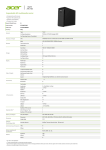
3. Carefully install the Master Controller Card in the left hand slot on the Master
Motherboard, located in the CPU bay (See Figure 3.)
4. 4100 Panels: Carefully install the RS-232/2120 Communication Card
(if Supplied) in the right hand slot on the Master Motherboard (See Figure 3).
5. 4120 Network Panels: Carefully install the RS-485 Network Interface Card in the
right hand slot on the Master Motherboard (See Figure 3).
Document No.: 4100-M011
March 1998
Issue 1.0
SIMPLEX 4100 EWIS
INSTALLATION MANUAL
Document No.: 4100-M011
Page 5
March 1998
Issue 1.0
Page 6
SIMPLEX 4100 EWIS
INSTALLATION MANUAL
Figure 3 Installing the System Cards
6. Carefully install each daughter Card into its proper slot on its motherboard (See
Figure 3.), making certain that the preset configuration of the daughter card
address switch, SW1, matches the daughter card address label (located next to
the daughter card’s motherboard).
•
The relationship between Address Switch SW1 and the card address label is
shown in Figure 4.
Figure 4 Card Address Label and Address Switch
•
The location of Address Switch SW1 on a typical daughter card is shown in
Figure 5.
Document No.: 4100-M011
March 1998
Issue 1.0
SIMPLEX 4100 EWIS
INSTALLATION MANUAL
Page 7
Figure 5 Location of Address Switch SW1 on a Typical 4100 Daughter Card
7. Make certain that all cables and wiring harness are connected in original locations
as shipped from the factory.
•
Refer to Simplex Field Wiring Diagram (Part No. 841-731).
Document No.: 4100-M011
March 1998
Issue 1.0
Page 8
SIMPLEX 4100 EWIS
INSTALLATION MANUAL
8. Make certain that all system wiring is terminated at specified terminal locations as
specified in the Simplex Field Wiring Diagram (Part No. 841-731).
9. Perform a complete system test of all installed devices.
10. Install the retainer panel on the back box with the retainer clips at the top of the
back box (See Figure 6).
Document No.: 4100-M011
March 1998
Issue 1.0
SIMPLEX 4100 EWIS
INSTALLATION MANUAL
Page 9
Figure 6 Installing the Retainer Panel
Document No.: 4100-M011
March 1998
Issue 1.0
Page 10
SIMPLEX 4100 EWIS
INSTALLATION MANUAL
11. Secure the retainer panel using the retainer panel holding screws provided.
12. Remove the panel door from the door box.
Document No.: 4100-M011
March 1998
Issue 1.0
SIMPLEX 4100 EWIS
INSTALLATION MANUAL
Page 11
13. Mount the door on the back box using the following procedure (See Figure 7).
a) Lift and place the front door assembly bottom pin into back box hinge hole.
b) Lift and slide top bolt pin up and across to lower bolt pin.
c) Move front door assembly into place.
d) Lift top bolt pin up into locating hole, and slide bolt pin across to drop bolt pin
into holding plate.
e) The door is now mounted onto the back box.
Document No.: 4100-M011
March 1998
Issue 1.0
Page 12
Document No.: 4100-M011
SIMPLEX 4100 EWIS
INSTALLATION MANUAL
March 1998
Issue 1.0
SIMPLEX 4100 EWIS
INSTALLATION MANUAL
Page 13
Figure 7 Mounting the door on the Back Box
14. Close and lock the panel door.
2.3
INSTALL AND TAG ALL SYSTEM WIRING.
• See the SYSTEM POINT SUMMARY Report (Table 7) and the appropriate
page in the 4100 Field Wiring Diagram (841-731).
2.4
INSTALL THE PERIPHERAL DEVICES AND E.O.L. RESISTORS.
• See Section 3 Field Terminations for details of terminating peripheral
devices.
• See the Point Type column in the SYSTEM POINT SUMMARY Report for
device type.
NOTES:
A. The 748-200 System Hardware envelope contains the required
resistors.
• 3.3K (monitor zone) resistors are colour coded orange, orange, red
(and have a gold tolerance band); 10K (Notification appliance [signal]
circuit) resistors are colour coded brown, black, orange (and also have
a gold tolerance band).
• Resistors other than those described above will be used by the
Simplex Technical Representative (T.R.) during installation checkout.
B. Wire peripherals in accordance with the appropriate 4100 Field Wiring
Diagram (841-731).
C. Use a small screwdriver or ball point pen to set device address switches.
D. After setting the device address, mark the device’s address label
(Figure 9) to agree with the address switches.
Document No.: 4100-M011
March 1998
Issue 1.0
Page 14
Figure 8 Location of DIP Switches
on Typical Device
2.5
SIMPLEX 4100 EWIS
INSTALLATION MANUAL
Figure 9 Device Address Label
BAY DOOR OPTION.
See Figure 10
a. (If applicable) Mark the top of the ribbon cable. Then pull the cable
straight out of its connector.
b. Remove the hair-pin cotter pins (item 1) from the upper clevis pins
(item 2). Then push the clevis pins inward and lower the door.
c. Free the lower end of the retainer cable (item 3) by removing the screw
and washer (items 4 and 5).
d. Remove the hair-pin cotter pins (item 6) from the lower clevis pins
(item 7). Then push the clevis pins inward and remove the door.
e. Store the door and its hardware in a safe, clean and dry place until all
wires are terminated in the 4100 panel.
Document No.: 4100-M011
March 1998
Issue 1.0
SIMPLEX 4100 EWIS
INSTALLATION MANUAL
Page 15
Figure 10 Removing the Option Bay Door
Document No.: 4100-M011
March 1998
Issue 1.0
Page 16
2.6
SIMPLEX 4100 EWIS
INSTALLATION MANUAL
CHECK AND TERMINATE ALL ZONES
NOTES:
A.
Use the CARD SUMMARY BY LOCATION Report (Table 6) to determine the
location of the motherboard on which each specific circuit terminates.
• A stick-on “ADDRESS” label on each motherboard identifies that board’s
number.
B.
The above report is found within the computer printout portion of the Factory
Documentation.
C.
Use the terminal identifiers to find specific terminals.
• See Figure 11(Custom Terminal Wiring Identifiers) for typical custom
terminal wiring identifiers.
D.
Check each circuit for voltages, shorts or opens as follows:
1.
With the meter set on 300VAC, read the voltage across the circuit.
• Meter must read 0 volts.
2.
With the meter set on 60VDC, read the voltage across the circuit
again (this time in both directions).
• Meter must read 0 volts.
3.
With the meter set on OHMS x 10 and its (+) and (–) leads connected to
the circuit’s (+) and (–) wires respectively, check resistance.
• Readings must compare favourably with those shown in Table 1.
• If reading indicates an open in a circuit that includes a smoke detector,
make sure the detector head(s) are properly mounted and seated.
– Circuits always read “open” (infinity) if detector power is absent and
separately-powered devices (four-wire smoke detectors) are involved.
E.
Connect the wires to their terminals.
Document No.: 4100-M011
March 1998
Issue 1.0
SIMPLEX 4100 EWIS
INSTALLATION MANUAL
Page 17
Circuit Type
Meter Reading
Style B
(formerly Class B) Initiating Device (Zone) Circuit
From zone + to zone – (each zone)
3.3K ohms
From zone + to ground
Infinity
From zone – to ground
Infinity
Style D
(formerly Class A) Initiating Device (Zone) Circuit
From zone + to zone – (each zone)
Infinity
From zone + to ground
Infinity
From zone – to ground
Infinity
From zone + OUT to + IN
Less than 50 ohms
From zone – OUT to – IN
Less than 50 ohms
Style Y
(formerly Class B) Notification Appliance Circuit (each signal circuit)
From + to ground
Infinity
From – to ground
Infinity
Resistance across circuit
In one direction
10K ohms
In opposite direction
Less than 200 ohms
Style Z
(formerly Class A) Notification Appliance Circuit (each signal circuit)
From + to ground
Infinity
From – to ground
Infinity
From + OUT to + IN
Less than 50 ohms
From – OUT to – IN
Less than 50 ohms
Resistance across circuit
In one direction
Infinity
In opposite direction
Less than 200 ohms
Shielding
Shield to ground
Shield to –
Shield to +
Infinity
Infinity
Infinity
Table 1 Acceptable Zone and Signal Circuit Meter Readings
Document No.: 4100-M011
March 1998
Issue 1.0
Page 18
SIMPLEX 4100 EWIS
INSTALLATION MANUAL
2.7
COMPLETE INSTALLATION PROCEDURE
A.
Check and terminate all remaining circuits (AC Power, AUX, FB etc.).
B.
Dress the panel wiring
• Use the tie wraps in the system hardware envelope to neatly dress the panel
wiring.
C.
Install the option bay door.
D.
Call your local Simplex Branch Office (listed in the Yellow Pages) to install the
printed circuit boards and test the system.
ONLY SIMPLEX REPRESENTATIVES ARE AUTHORISED TO APPLY
AC OR BATTERY POWER TO THE 4100 EWIS SYSTEM.
Document No.: 4100-M011
March 1998
Issue 1.0
SIMPLEX 4100 EWIS
INSTALLATION MANUAL
2.8
Page 19
INSTALLATION CHECKLIST FOR SIMPLEX TECHNICAL REPRESENTATIVE
Step
Procedure
Page
U
1.
Use the Packing List in the “Layout” pages to verify
delivery/availability of all required system hardware. This
includes the printed circuit boards.
1
U
2.
Unlock, then open the panel door. Remove the retainer by
removing the top and bottom screws, then squeeze and
pull the two black plastic tabs located on the upper part of
the retainer. Lift the retainer from the back box.
3
U
3.
Visually inspect the 4100 system. Verify that all wiring is
connected to the panel, to include the unified ground.
3
U
4.
Use a volt/ohmmeter to check system wiring.
This
includes all wiring to the panel, local and remote
annunciators, etc. Check the AC power input to the power
supply. Repair required circuits prior to powering up the
system.
3
U
5.
Check jumpers, switches, capacitors and resistors on all
system printed circuit boards. Match the address label on
the motherboard to the address label on the daughter
board, then install each daughter board.
3
U
6.
Install all wiring harnesses and cables (except battery).
This includes auxiliary relay and signal cables.
9
U
7.
Apply power to the system.
60
• If the system is trouble-free, perform “System Test
Procedures”.
68
• If the system displays abnormal conditions, perform
troubleshooting procedures.
70
Document No.: 4100-M011
March 1998
Issue 1.0
Page 20
SIMPLEX 4100 EWIS
INSTALLATION MANUAL
2.8.1 Visual Inspection
A visual inspection of the panel should be performed prior to installation of printed
circuit boards, as they obstruct the view of panel terminations when installed.
Visually inspect for the following:
(a)
Neat terminations within the panel.
(b)
System wiring is complete and unused circuits are terminated.
(c)
Terminations are tight.
(d)
Ribbon cables from CPU board are properly installed (both ends).
(e)
Battery cable is connected to the battery test facility P9 of the power master
supply or P1 of an expansion power supply.
(f)
Green ground screw is connected to a unified building ground.
(h)
Inspect local and remote annunciators connections.
(i)
Verify that system is clean and free from wire clippings.
(j)
Switches are in the proper position (toggle switches are down).
(k)
Verify that the configuration chip, and revision shown in the main menu, match
the Programmer’s Report then check the following:
(i)
(ii)
(iii)
(iv)
File name
Order number
Revision number
Date
(8 digits - example: 809005A)
(X digits - example: XXXXXX)
(3 digits - example: 006)
(9 digits - example: 07-JUL-88)
2.8.2 Install Printed Circuit Boards
There are several types of motherboards and printed circuit boards for the 4100
system. Each printed circuit board must be plugged into its proper motherboard for
power and communications with the CPU.
Each 4100 printed circuit board has an 8 bit DIP switch (SW1) which is used to set
its address and communication baud rate. Verify each address and baud rate prior
to installation of each board. The system may contain up to 119 printed circuit cards
(each has its own address). The CPU board is always address 0. Each printed
circuit board address is a binary address which corresponds with a Custom Terminal
Wiring Identifier (white label) on its motherboard, daughterboard and the
Programmer’s Report.
Match the address label on the motherboard to the address label on the
daughterboard, then install each daughterboard. Table 3 (page 26) shows a binary
switch setting table which may be used to determine binary address and baud rate.
Document No.: 4100-M011
March 1998
Issue 1.0
SIMPLEX 4100 EWIS
INSTALLATION MANUAL
Page 21
Dip switch positions 2 through 8 are used for addressing, while dip switch position 1
is used for baud rates selection.
Check switch settings, jumpers and resistors on each printed circuit board prior to
installation.
Use the Custom Terminal Wiring Identifiers (same address on motherboard and
daughterboard), Layout pages and the Programmer’s Report to determine proper
address and placement for each printed circuit board. The dip switch on each board
has been set to its correct binary address at the factory. This binary address
corresponds with a Custom Terminal Wiring Identifier (label) on each motherboard.
Match the address on the daughter card with the address label on the motherboard,
then insert the card. See Figure 6 (Card Detail Report) for card address example
and Figure 18 for an example of a Custom Terminal Wiring Identifier (address 5 for
card #5 is shown).
Install the printed circuit boards from left to right, and from top to bottom.
Document No.: 4100-M011
March 1998
Issue 1.0
Page 22
SIMPLEX 4100 EWIS
INSTALLATION MANUAL
Figure 11 Custom Terminal Wiring Identifiers
Document No.: 4100-M011
March 1998
Issue 1.0
SIMPLEX 4100 EWIS
INSTALLATION MANUAL
Page 23
1
2
MSB
3
4
5
6
7
8
LSB
Side View of Dip Switch
ON
SW-1
OFF
SW1-2
SW1-3
SW1-4
SW1-5
SW1-6
SW1-7
CPU MODULE IS ALWAYS ADDRESS 0
U
S
E
D
F
O
R
B
A
U
D
R
A
T
E
ON
ON
ON
ON
ON
ON
ON
ON
ON
ON
ON
ON
ON
ON
ON
ON
ON
ON
ON
ON
ON
ON
ON
ON
ON
ON
ON
ON
ON
ON
ON
ON
ON
ON
ON
ON
ON
ON
ON
ON
ON
ON
ON
ON
ON
ON
ON
ON
ON
ON
ON
OFF
OFF
OFF
ON
ON
ON
ON
ON
ON
ON
OFF
OFF
OFF
OFF
OFF
OFF
OFF
OFF
ON
ON
ON
ON
ON
ON
OFF
OFF
OFF
OFF
ON
ON
ON
ON
OFF
OFF
OFF
OFF
ON
ON
ON
ON
OFF
OFF
ON
ON
OFF
OFF
ON
ON
OFF
OFF
ON
ON
OFF
OFF
ON
ON
OFF
SW1-8
CPU
= ADDRESS 0
OFF
ON
OFF
ON
OFF
ON
OFF
ON
OFF
ON
ON
ON
OFF
ON
OFF
ON
OFF
ON
=
=
=
=
=
=
=
=
=
=
=
=
=
=
=
=
=
=
OFF
= ADDRESS 119
ADDRESS 1
ADDRESS 2
ADDRESS 3
ADDRESS 4
ADDRESS 5
ADDRESS 6
ADDRESS 7
ADDRESS 8
ADDRESS 9
ADDRESS 10
ADDRESS 11
ADDRESS 12
ADDRESS 13
ADDRESS 14
ADDRESS 15
ADDRESS 16
ADDRESS 17
ADDRESS 18
CONTINUES TO A BINARY 119
ON
OFF
OFF
OFF
ON
OFF
OFF
Table 2 Printed Circuit Board Addresses
Document No.: 4100-M011
March 1998
Issue 1.0
Page 24
SIMPLEX 4100 EWIS
INSTALLATION MANUAL
DIP SWITCH SW1
ADDRESS AND BAUD RATE SELECT
SWITCH POSITION
#1
#2
BRS
MSB
#3
#4
#5
#6
#7
#8
LSB
BRS = BAUD RATE SELECT
0-9600 baud (INTERNAL/REMOTE)
ON = 0
OFF = 1
Table 3 All Expansion Cards
Document No.: 4100-M011
March 1998
Issue 1.0
SIMPLEX 4100 EWIS
INSTALLATION MANUAL
Page 25
PLUGGABLE RESISTOR SETTINGS
DRIVE #
RESISTOR #
1
2
3
4
5
6
7
8
9
10
11
12
13
14
15
16
17
18
19
20
21
22
23
24
20
21
22
23
24
25
26
27
28
29
30
31
32
33
34
35
36
37
38
39
40
41
42
43
INPUT
2K
2K
2K
2K
2K
2K
2K
2K
2K
2K
2K
2K
2K
2K
2K
2K
2K
2K
2K
2K
2K
2K
2K
2K
.5W
.5W
.5W
.5W
.5W
.5W
.5W
.5W
.5W
.5W
.5W
.5W
.5W
.5W
.5W
.5W
.5W
.5W
.5W
.5W
.5W
.5W
.5W
.5W
For Input Contact Monitors
OUTPUT
20 OHM
20 OHM
20 OHM
20 OHM
20 OHM
20 OHM
20 OHM
20 OHM
20 OHM
20 OHM
20 OHM
20 OHM
20 OHM
20 OHM
20 OHM
20 OHM
20 OHM
20 OHM
20 OHM
20 OHM
20 OHM
20 OHM
20 OHM
20 OHM
1W
1W
1W
1W
1W
1W
1W
1W
1W
1W
1W
1W
1W
1W
1W
1W
1W
1W
1W
1W
1W
1W
1W
1W
For Relays LED/Lamps
Table 4 24 Point Graphic I/O Card Pluggable Resistors
NOTE: Systems are shipped from the factory with 3.3K OHM resistors. Use 3.3K
OHM resistors for contact monitors and 20 OHM resistors for RELAY or
LED/lamp outputs.
Document No.: 4100-M011
March 1998
Issue 1.0
Page 26
SIMPLEX 4100 EWIS
INSTALLATION MANUAL
This page intentionally left blank
Document No.: 4100-M011
March 1998
Issue 1.0
SIMPLEX 4100 EWIS
INSTALLATION MANUAL
Page 27
3. FIELD TERMINATIONS
This section describes procedures to successfully install and terminate all field
equipment that is to be terminated to the 4100 EWIS System.
3.1
SPEAKER LINE TERMINATIONS
8225
or
8250
Amplifier
Card
100V
IN
100V
OUT
10k End of Line
at last speaker in
Figure 12 Amplifier Card Terminations for Speakers
Document No.: 4100-M011
March 1998
Issue 1.0
Page 28
SIMPLEX 4100 EWIS
INSTALLATION MANUAL
Speaker lines are terminated in the 8225 or 8250 Amplifier card.
Only one Zone can be terminated on each Amplifier card, speakers can be wired in
parallel, and terminated with a 10k End of Line Resistor.
The terminating connections are located at the bottom of the front panel on the
amplifier card (See
Figure 12).
Speakers are terminated across the 100v output line as shown in
Document No.: 4100-M011
March 1998
Issue 1.0
SIMPLEX 4100 EWIS
INSTALLATION MANUAL
Page 29
Figure 12.
Wiring to the speaker lines is supervised via a 10k end of line resistor placed across
the last speaker in each zone.
The capacitor fly lead is connected to the transformer primary winding. Select either
0.5 W, 1 W, 2 W, or 5 W terminal for the required power output for the speaker.
Document No.: 4100-M011
March 1998
Issue 1.0
Page 30
Document No.: 4100-M011
SIMPLEX 4100 EWIS
INSTALLATION MANUAL
March 1998
Issue 1.0
SIMPLEX 4100 EWIS
INSTALLATION MANUAL
3.2
Page 31
EMERGENCY ALARM INITIATING DEVICES TERMINATIONS
3k3
EOLR
Other Manual
Call Point Zones
ZN1 ZN2 ZN3 ZN4
5002
Monitor Card
ZN5 ZN6 ZN7 ZN8
Other Manual
Call Point Zones
Figure 13 Monitor Card Terminations for Manual Call Points
Document No.: 4100-M011
March 1998
Issue 1.0
Page 32
SIMPLEX 4100 EWIS
INSTALLATION MANUAL
Manual Call Points are terminated in the 4100-5002 monitor card.
There are 8 zones per card and are labelled ZN1 to ZN8 (See
Figure 13).
Document No.: 4100-M011
March 1998
Issue 1.0
SIMPLEX 4100 EWIS
INSTALLATION MANUAL
Page 33
One Zone can terminate many Manual Call Points, but they must be wired in parallel,
and terminated with a 3k3 End of Line Resistor across the last manual call point.
The terminating connections are located at the Top and Bottom of the motherboard.
Document No.: 4100-M011
March 1998
Issue 1.0
Page 34
3.3
SIMPLEX 4100 EWIS
INSTALLATION MANUAL
FIRE INDICATOR PANEL EWIS TRIP TERMINATIONS
3k3
EOLR
Other FIP TRIPs
Fire Indicator
Panel Trip
ZN1 ZN2 ZN3 ZN4
5002
Monitor Card
ZN5 ZN6 ZN7 ZN8
Other FIP TRIPs
Figure 14 Monitor Card Terminations for FIP trips
Document No.: 4100-M011
March 1998
Issue 1.0
SIMPLEX 4100 EWIS
INSTALLATION MANUAL
Page 35
The Fire Indicator Panel Trip can be terminated in the 4100-5002-monitor card.
There are 8 Input zones per card and are labelled ZN1 to ZN8 (See
Figure 14).
Each input zone monitors a set of Normally Open Contacts located in the Fire
Indicator Panel and is terminated with a 3K3 End Of Line Resistor.
Document No.: 4100-M011
March 1998
Issue 1.0
Page 36
SIMPLEX 4100 EWIS
INSTALLATION MANUAL
One of the monitor card terminations can be used.
The terminating connections are located at the Top and Bottom of the motherboard.
Document No.: 4100-M011
March 1998
Issue 1.0
SIMPLEX 4100 EWIS
INSTALLATION MANUAL
3.4
Page 37
VISUAL ALARM DEVICE LINE TERMINATIONS
{
10k
Additional
EOLR
One
Evacuation
Zone
Visual
Alarm
Devices
EVAC
Visual Alarm Device
10k
EOLR
ALERT
Visual Alarm Device
NOTE: Only one
connection per port
SIG3 SIG4
DO
NO
USE
SIG5 SHLD
4322
Signal Card
SIG6 SIG7 SIG8
SHLD
DO
NO
USE
Additional
Visual Alarm Devices
Figure 15 Signal Card Terminations for Visual Alarms Devices
Document No.: 4100-M011
March 1998
Issue 1.0
Page 38
SIMPLEX 4100 EWIS
INSTALLATION MANUAL
Visual Alarm Devices are terminated in the 4100-4322-signal card.
There are 6 signal ports per card and are labelled SIGx to SIGx. Where x
corresponds to a signal port number.
Visual Alarm Devices are terminated on each port of the signal card.
For each Evacuation Zone, two signal ports are assigned.
1. For the Alert Strobe(s)
2. For Evacuation Strobe(s)
Each Visual Alarm Device must terminated with a 10k End of Line Resistor.
The terminating connections are located at the Top and Bottom of the motherboard.
Each port can source up to 2 Amps at 24 VDC for driving strobes.
If driving a number of strobes, ensure that the correct size cable is used to minimise
voltage drop on the unit.
Document No.: 4100-M011
March 1998
Issue 1.0
SIMPLEX 4100 EWIS
INSTALLATION MANUAL
3.5
Page 39
WIP LINE TERMINATIONS
Additional
WIPs
WIP
10k
EOLR
Note: Only One WIP
Phone off each port
DO
NO
SIG3 SIG4 SIG5 USE
SHLD
4322
Signal Card
SIG6 SIG7 SIG8
SHLD
DO
NO
USE
Additional
WIPs
Figure 16 Signal Card Terminations for WIPs
Document No.: 4100-M011
March 1998
Issue 1.0
Page 40
SIMPLEX 4100 EWIS
INSTALLATION MANUAL
WIP Devices are terminated in the 4100-4322-signal card.
There are 6 ports per card and are label SIG3 to SIG8. The cable shields should be
connected in the termination labelled SHLD (See
Figure 16).
Only One WIP phone can be terminated on each port of the signal card. These
phones must be Simplex WIP phones Part Number: - 2084-9106.
Document No.: 4100-M011
March 1998
Issue 1.0
SIMPLEX 4100 EWIS
INSTALLATION MANUAL
Page 41
The last Each WIP phone in each zone must terminated with a 10k End of Line
Resistor.
The terminating connections are located at the Top and Bottom of the motherboard.
Document No.: 4100-M011
March 1998
Issue 1.0
Page 42
3.6
SIMPLEX 4100 EWIS
INSTALLATION MANUAL
P.A. MICROPHONE TERMINATIONS
Note S = Cable Shield
MECP
SECP Terminations REM MIC
Terminations
Terminations
Figure 17 Pre Amplifier Board Terminations for PA
Document No.: 4100-M011
March 1998
Issue 1.0
SIMPLEX 4100 EWIS
INSTALLATION MANUAL
Page 43
The P.A Microphone is terminated on the pre amplifier card.
The pre amplifier card is used to terminate the Master Emergency Control Point
Microphone, the Secondary Emergency Control Point Microphone, and remote
microphone.
The terminating connections are located at the bottom of the pre amplifier
board (See
Document No.: 4100-M011
March 1998
Issue 1.0
Page 44
SIMPLEX 4100 EWIS
INSTALLATION MANUAL
Figure 17)
Document No.: 4100-M011
March 1998
Issue 1.0
SIMPLEX 4100 EWIS
INSTALLATION MANUAL
3.7
Page 45
BACKGROUND MUSIC TERMINATIONS
Note S = Cable Shield
BGM
Terminations
Figure 18 Pre Amplifier Board Terminations for BGM
The Background Music input is terminated on the pre amplifier card.
Document No.: 4100-M011
March 1998
Issue 1.0
Page 46
SIMPLEX 4100 EWIS
INSTALLATION MANUAL
The terminating connections are located at the bottom of the pre amplifier
board (See
Figure 18)
3.8 NETWORK WIP PHONE TERMINATION
The Network Master WIP phone is terminated on the Master Phone Assembly
4100-0205.
Document No.: 4100-M011
March 1998
Issue 1.0
SIMPLEX 4100 EWIS
INSTALLATION MANUAL
Page 47
The Network Master WIP Phone is the start and finish of the WIP Phone Network.
The WIP Phone Network leaves the master Node from port P3 and is looped through
each slave node and returns to the master node on port P4. (See
Figure 19)
Figure 19 Master WIP Phone Network
Document No.: 4100-M011
March 1998
Issue 1.0
Page 48
SIMPLEX 4100 EWIS
INSTALLATION MANUAL
3.8.1 Network WIP Phone Termination – Master Node
The WIP Master Phone is terminated on connector P6. Only use approved master
phone part number 2084-9106.
The next node in the network is terminated on connector P4.
The last node in the network is terminated on connector P3.
From Last Node
in Network
To First Node
in Network
Not Used
1 2 3 4 5 6 7 8
P5
TB1
P3
P4
4100-0205
IC
Power
&
Communication
connections
P6
Not Used
Master
Phone
Handset
Figure 20 WIP Network Master Node Phone Terminations
The Master Phone Handset terminations are on terminals labelled 1 & 2.
The positive line on terminal 1 and the negative line on terminal 2.
Document No.: 4100-M011
March 1998
Issue 1.0
SIMPLEX 4100 EWIS
INSTALLATION MANUAL
Page 49
3.8.2 Network WIP Phone Termination – Slave Node
The WIP Master Phone is terminated on connector P6. Only use approved master
phone part number 2084-9106.
The network connections for slave node WIP Phones in the WIP Phone network are
terminated on terminal block TB1 termination 7,8.
The cabling from the previous node and the next node in the network are
terminated together. See
Figure 21
From Previous Node
in Network
To Next Node
in Network
Not Used
1 2 3 4 5 6 7 8
P5
TB1
Document No.: 4100-M011
4100-0205
P3
P4
March 1998
Issue 1.0
Page 50
SIMPLEX 4100 EWIS
INSTALLATION MANUAL
Figure 21 WIP Network Slave Node Phone Terminations
The Master Phone Handset terminations are on terminals labelled 1 & 2.
The positive line on terminal 1 and the negative line on terminal 2.
3.9 SECP TERMINATION
SECP terminations are site configuration dependent and will be designated at time of
system configuration.
Document No.: 4100-M011
March 1998
Issue 1.0
SIMPLEX 4100 EWIS
INSTALLATION MANUAL
4
Page 51
PROGRAMMERS REPORT
The Programmer’s Report is used to identify peripheral connections within the panel
and specifies system operational data.
The 13 sections within the Programmer’s Report are shown in Tables 5 through 17,
and explained in each section.
4.1
GENERAL INFORMATION
This section contains branch office required information. It details branch personnel
involved with the system, system power data, agency, and software information.
The software revision must match the system CFIG chip label for proper operation of
the LCD display.
-------------------------------------------------------------------------------XYZ BUILDING
GENERAL INFORMATION
Page
1
2796 node:1 rev:6
14:41:55, WED, 25-MAR-98
-------------------------------------------------------------------------------4100 Fire Alarm System
GENERAL
Simplex Time Recorder Co.
INFO
Node Number: 1
System Type: 4100+
Job Filename
Job Title
Order Number
Customer
Customer Contact
Contractor
Salesperson
Branch Number
Branch Location
Programmed by
:
:
:
:
:
:
:
:
:
:
2796
XYZ BUILDING
Agency Approval
NFPA Standard
Standby Generator?
Hours of Standby Battery
:
:
:
:
NONE
NONE
NO
Comments :
:
Job Rev : 6
Built Rev : 6
Built Date : 17-Mar-98 15:22
Programmer Rev
System Defaults Rev
Database (DBF) Format
CFIG Format
:
:
:
:
Current
------7.03
79
80
0
As Built
-------7.03
79
80
0
Table 5 GENERAL INFORMATION REPORT
Document No.: 4100-M011
March 1998
Issue 1.0
Page 52
4.2
SIMPLEX 4100 EWIS
INSTALLATION MANUAL
CARD SUMMARY BY LOCATION
The Card Summary by Location shows the number of cards within the system. This
page should be used to verify delivery of system cards from the factory. It also
shows a decimal card number which is the address for that printed circuit board.
Addresses 3 and 9 are shown below on Custom Terminal Wiring Identifiers.
-------------------------------------------------------------------------------XYZ BUILDING
CARD SUMMARY BY LOCATION
Page
3
2796 node:1 rev:6
14:41:55, WED, 25-MAR-98
-------------------------------------------------------------------------------CARD
CARD LOCATION LISTING:
LOCATION
LOCAL CONTROLLER UNIT:
DAUGHTER CARDS:
Card
----0
1
2
3
4
5
8
9
10
11
12
13
15
19
20
21
22
23
Card Type
---------------------------------------(7003) 4100+ Master Controller
(3003) 8 Pt, 3 Amp Relay w/ Feedback
(0304) Remote Unit Interface (RUI)
(5002) 8 Zn Class B Monitor (IDC) w/Sup
(5002) 8 Zn Class B Monitor (IDC) w/Sup
(6005) Power Supply/Charger
(5002) 8 Zn Class B Monitor (IDC) w/Sup
(5002) 8 Zn Class B Monitor (IDC) w/Sup
(5002) 8 Zn Class B Monitor (IDC) w/Sup
(5002) 8 Zn Class B Monitor (IDC) w/Sup
(5002) 8 Zn Class B Monitor (IDC) w/Sup
(5002) 8 Zn Class B Monitor (IDC) w/Sup
(0205) Phone Card
(4332) 3 Input Class A Signal w/Sup
(4332) 3 Input Class A Signal w/Sup
(4332) 3 Input Class A Signal w/Sup
(4332) 3 Input Class A Signal w/Sup
(4332) 3 Input Class A Signal w/Sup
Zone Range
-----------------
Card Type
---------------------------------------64 LED / 64 Sw Controller
(0301) 64 LED / 64 Sw Controller
(0301) 64 LED / 64 Sw Controller
(0301) 64 LED / 64 Sw Controller
(0301) 64 LED / 64 Sw Controller
(0301) 64 LED / 64 Sw Controller
(0301) 64 LED / 64 Sw Controller
Zone Range
-----------------
AUX3-10
RUI 1
ZN1-8
ZN9-16
ZN17-24
ZN25-32
ZN33-40
ZN41-48
ZN49-56
ZN57-64
SIG3-8
SIG9-14
SIG15-20
SIG21-26
SIG27-32
ANNUNCIATORS:
Annun Card
----- ----0
0
6
7
14
16
17
18
REMOTE UNIT INTERFACE 1 (RUI 1):
Type Unit
--------Ann
1
Ann
1
Ann
1
Ann
1
Card
---24
26
27
25
Card Type
---------------------------------------(0302) 24 Pt Graphic Interface
(0302) 24 Pt Graphic Interface
(0302) 24 Pt Graphic Interface
(6005) Power Supply/Charger
Zone Range
----------------IO1-24
IO25-48
IO49-72
Table 6 CARD SUMMARY BY LOCATION REPORT
Document No.: 4100-M011
March 1998
Issue 1.0
SIMPLEX 4100 EWIS
INSTALLATION MANUAL
4.3
Page 53
SYSTEM POINT SUMMARY
The System Point Summary is of primary importance to the installer. Simplex
personnel must provide this information prior to installation. Call your local Simplex
branch office, which is listed in the Yellow Pages, and request this information be
provided. This is used in conjunction with the Layout pages, to determine wiring
terminations and the information shown below.
4.3.1 Zone Name
Zone names reference the custom label to specific points for actual customer wiring.
They include monitor zones (ZNx), signals (SIGx), auxiliary relays (AUXx), 24 point
I/O (PMx) and feedback (FBx) numbers. Zones, signals, relays, feedbacks, etc., are
shown in numerical sequence.
4.3.2 Address
Each printed circuit board requires a unique address. Address 0 identifies the
master termination module. Up to 119 addresses, one per printed circuit board, may
be used in a system. Addresses may or may not be in sequential order, but the
report always starts with address 0. Two address labels are used for each
mother/daughter board combination. The mother board will have its unique address
label next to the PC board connector. The daughter board will have an identical
label.
4.3.3 Custom Label
The custom label identifies a location within the building or area, and contains
additional information concerning each circuit. Also included with the custom label is
the corresponding zone name. This ties the custom label to a zone name and allows
the installer to identify where field wires are terminated, according to zone name.
Examples:
__________________________________________________________
1ST FLOOR SOUTH WING WIP
SIGNAL 2
3RD FLOOR EAST WING ALERT STROBES
SIGNAL 40_
4.3.4 Point Type
This is the type of device (indicating appliance, initiating device, relays, etc.)
connected to each circuit. Each device type is abbreviated. An operational
description may also be included in the abbreviation.
Example:
_____________________________________
AHUM (Air Handling Unit Monitor)
PRI (Primary Elevator Capture)___
The installer should use the System Point Summary when marking wires to the 4100
panel. These markings should include zones (ZNx+, ZNx--), signals (SIGx), etc., for
each circuit within the system. Marking each wire in this matter will facilitate
termination and checking of the wiring in the 4100 panel.
Document No.: 4100-M011
March 1998
Issue 1.0
Page 54
NOTE:
SIMPLEX 4100 EWIS
INSTALLATION MANUAL
The SYSTEM POINT SUMMARY Report is found within the computer
printout portion of the Factory Documentation.
--------------------------------------------------------------------------------XYZ
BUILDING
SYSTEM POINT SUMMARY
Page
62796 node:1
rev:6
14:41:55, WED, 25-MAR-98
-------------------------------------------------------------------------------POINT SUMMARY
System Point Summary (ascending by zone name):
ZONE
Zone Name
--------SIG31
SIG32
AUX3
AUX4
AUX5
AUX6
AUX7
AUX8
AUX9
AUX10
FB3
FB4
FB5
FB6
FB7
FB8
FB9
FB10
IO1
IO2
IO3
IO4
IO5
IO6
IO7
IO8
IO9
IO10
IO11
IO12
IO13
IO14
IO15
IO16
IO17
IO18
IO19
IO20
IO21
IO22
IO23
IO24
IO25
IO26
IO27
IO28
Device
Custom Label
Type
---------------------------------------- ------SIGNAL CARD 23 CIRCUIT SIG31
SIGNAL CARD 23 CIRCUIT SIG32
BATTERY TEST OUTPUT
AUX3
SYSTEM FAULT
AUX4
BRIGADE ALARM 1
AUX5
BRIGADE ALARM 2
AUX6
GFA OUTPUT 1
AUX7
GFA OUTPUT 2
AUX8
FIRE ALARM BELL
AUX9
SPARE
AUX10
***** DOOR SWITCH ***** FEEDBACK PT FB3
AUX RELAY CARD 4 FEEDBACK PT FB4
AUX RELAY CARD 4 FEEDBACK PT FB5
AUX RELAY CARD 4 FEEDBACK PT FB6
AUX RELAY CARD 4 FEEDBACK PT FB7
AUX RELAY CARD 4 FEEDBACK PT FB8
AUX RELAY CARD 4 FEEDBACK PT FB9
FIP MCP
FEEDBACK PT FB10
AMPLIFIER #1 HAS FAILED
AMPLIFIER #1 ALERT
AMPLIFIER #1 EVAC
AMPLIFIER #1 P.A.
AMPLIFIER #2 HAS FAILED
AMPLIFIER #2 ALERT
AMPLIFIER #2 EVAC
AMPLIFIER #2 P.A.
AMPLIFIER #3 HAS FAILED
AMPLIFIER #3 ALERT
AMPLIFIER #3 EVAC
AMPLIFIER #3 P.A.
AMPLIFIER #4 HAS FAILED
AMPLIFIER #4 ALERT
AMPLIFIER #4 EVAC
AMPLIFIER #4 P.A.
UNUSED
UNUSED
UNUSED
UNUSED
UNUSED
UNUSED
UNUSED
UNUSED
AMPLIFIER #5 HAS FAILED
AMPLIFIER #5 ALERT
AMPLIFIER #5 EVAC
AMPLIFIER #5 P.A.
Point
PNIS
Type
Code
------- ----------PHONE
PHONE
RELAY
RELAY
RELAY
RELAY
RELAY
RELAY
RELAY
RELAY
ONOFF
ONOFF
ONOFF
ONOFF
ONOFF
ONOFF
ONOFF
ONOFF
TSWITCH
RELAY
RELAY
RELAY
TSWITCH
RELAY
RELAY
RELAY
TSWITCH
RELAY
RELAY
RELAY
TSWITCH
RELAY
RELAY
RELAY
USWITCH
USWITCH
USWITCH
USWITCH
USWITCH
USWITCH
USWITCH
USWITCH
TSWITCH
RELAY
RELAY
RELAY
Table 7 SYSTEM POINT SUMMARY REPORT
NOTES:
A. Custom label information tells you where the circuit goes.
B. At both ends of each circuit, tag wires with zone name and polarity (in cases
where polarity applies).
• For example, SIG 3+ and SIG 3-.
Document No.: 4100-M011
March 1998
Issue 1.0
SIMPLEX 4100 EWIS
INSTALLATION MANUAL
4.4
Page 55
SYSTEM OPTION SUMMARY
The System Options Summary lists all standard system operations.
operations are shown with the word “YES”.
Enabled
-------------------------------------------------------------------------------XYZ BUILDING
SYSTEM OPERATION
Page
2
2796 node:1 rev:6
14:41:55, WED, 25-MAR-98
-------------------------------------------------------------------------------OPTIONS
SUMMARY
Standard System Operations
----------------------------Alarm Silence Inhibit.......
Time Limit Signal Control...
System Trouble Reminder.....
Dedicated Waterflow Signals.
Sprinkler Supv. Operation...
Alarm Verification Setup....
Individual Acknowledge .....
Elevator Recall Operation...
Non-Steady Audible Evac Sig.
Non-Steady Visual Evac Sig.
Door Holder Operation.......
Enabled?
-------NO
NO
NO
NO
NO
NO
NO
NO
NO
NO
NO
Settings
------------------------------------
Expanded System Operations
----------------------------24-Hr Time/Date Format......
Coding Group Configuration..
Audio Coding Configuration..
Audio Option Configuration..
Walk Test by Group..........
Non-General Alarm Operation.
Pre-Programmed User Lists...
Temperature in Centigrade...
Default Local Mode..........
Paging Channel Selection....
Enabled?
-------NO
NO
NO
NO
NO
NO
YES
NO
YES
NO
Settings
-----------------------------------12 HOUR
Other Selections
----------------------------Access Levels
Non-Default Passcodes
City Connect
Custom Control
Enabled?
--------
Settings
-----------------------------------*
NO
YES
GLOBAL
*
FAHRENHEIT
Form 'C' Dry Contact
Program: 3, 4, 5, 7
* Operation ENABLED. See Options Detail Report for full description.
Table 8 SYSTEM OPTIONS SUMMARY
Document No.: 4100-M011
March 1998
Issue 1.0
Page 56
4.5
SIMPLEX 4100 EWIS
INSTALLATION MANUAL
UNIT DETAIL REPORT
The Unit Detail Report shows detailed information regarding each printed circuit
board as well as software cards (pseudos) in the system. Custom information is
shown for each type of card, such as card number, card address (binary), circuits on
the card, circuit types, custom labels, and coding information, if applicable.
-------------------------------------------------------------------------------XYZ BUILDING
UNIT DETAIL REPORT
Page 62
2796 node:1 rev:6
14:41:55, WED, 25-MAR-98
-------------------------------------------------------------------------------UNIT No: 0
UNIT 0
CARD No:
0 (base)
0-4
64 LED / 64 Sw Controller
CONTROL PANEL LED/SWITCH ANNUNCIATOR 0
UNIT COMPOSITION:
Card No
------0
6
7
14
16
17
18
1
2
3
4
5
8
9
10
11
12
13
19
20
21
22
23
Card Type
---------------------------------------64 LED / 64 Sw Controller
(0301) 64 LED / 64 Sw Controller
(0301) 64 LED / 64 Sw Controller
(0301) 64 LED / 64 Sw Controller
(0301) 64 LED / 64 Sw Controller
(0301) 64 LED / 64 Sw Controller
(0301) 64 LED / 64 Sw Controller
(3003) 8 Pt, 3 Amp Relay w/ Feedback
(0304) Remote Unit Interface (RUI)
(5002) 8 Zn Class B Monitor (IDC) w/Sup
(5002) 8 Zn Class B Monitor (IDC) w/Sup
(6005) Power Supply/Charger
(5002) 8 Zn Class B Monitor (IDC) w/Sup
(5002) 8 Zn Class B Monitor (IDC) w/Sup
(5002) 8 Zn Class B Monitor (IDC) w/Sup
(5002) 8 Zn Class B Monitor (IDC) w/Sup
(5002) 8 Zn Class B Monitor (IDC) w/Sup
(5002) 8 Zn Class B Monitor (IDC) w/Sup
(4332) 3 Input Class A Signal w/Sup
(4332) 3 Input Class A Signal w/Sup
(4332) 3 Input Class A Signal w/Sup
(4332) 3 Input Class A Signal w/Sup
(4332) 3 Input Class A Signal w/Sup
Display Card Point Usage
-----------------------0 LEDs /
0 SWs
64 LEDs / 32 SWs
64 LEDs / 40 SWs
64 LEDs / 40 SWs
64 LEDs / 40 SWs
64 LEDs / 32 SWs
0 LEDs /
0 SWs
N/A
N/A
N/A
N/A
N/A
N/A
N/A
N/A
N/A
N/A
N/A
N/A
N/A
N/A
N/A
N/A
NOTE: Card 0, Annun 0 = Master Controller slot 4
Table 9 UNIT DETAIL REPORT
Document No.: 4100-M011
March 1998
Issue 1.0
SIMPLEX 4100 EWIS
INSTALLATION MANUAL
4.6
Page 57
ANNUNCIATOR REPORT
The Local Annunciator Report is shown first (if applicable), followed by the Remote
Annunciator Report (if applicable). The first page of these reports shows the
controller/card number, position, and the type of display cards selected. The next
pages will show the point, switch mode, reference address, reference custom label,
and the reference type. A typical Local Annunciator Report is shown in Figure 7.
-------------------------------------------------------------------------------XYZ BUILDING 1
CARD DETAIL REPORT
Page 11
909015J node:1 rev:1
04:39:17, WED, 14-MAY-97
-------------------------------------------------------------------------------CARD No:
5
LED/SW
(0301) 64 LED / 64 Sw Controller
CARD
UNIT No: 0
5
addr 00000101
sw1 12345678
CONTROLLER CARD CONFIGURATION DETAIL:
Controller
Card No
---------5
Display Card
-----------1
2
3
4
5
6
7
8
9
10
11
12
13
14
15
16
Display Card Type
----------------------------L403 - 8 Momen Sw/8 Red LED
L405 - 8 Momen Sw/16 Red-Yel LED
L405 - 8 Momen Sw/16 Red-Yel LED
L405 - 8 Momen Sw/16 Red-Yel LED
0409 - Blank Display Card
0409 - Blank Display Card
0409 - Blank Display Card
0102 - Battery Meters (amp/volt)
0409 - Blank Display Card
0409 - Blank Display Card
0409 - Blank Display Card
0409 - Blank Display Card
0409 - Blank Display Card
0409 - Blank Display Card
0409 - Blank Display Card
0409 - Blank Display Card
Table 10 LOCAL ANNUNCIATOR REPORT
Document No.: 4100-M011
March 1998
Issue 1.0
Page 58
4.7
SIMPLEX 4100 EWIS
INSTALLATION MANUAL
DIGITAL PSEUDO POINT SUMMARY
The Digital Pseudo Point Summary shows all digital pseudo points within the system.
It also identifies the custom labels, and pseudo type for each digital pseudo point
within the system.
-------------------------------------------------------------------------------XYZ BUILDING
DIGITAL PSEUDO POINT SUMMARY
Page 20
2796 node:1 rev:6
14:41:55, WED, 25-MAR-98
-------------------------------------------------------------------------------CARD No: 132
DIGITAL SUMMARY
256 Point Digital Pseudo
P1024 - P1075
Point
------P1024
P1025
P1026
P1027
P1028
P1029
P1030
P1031
P1033
P1034
P1035
P1036
P1037
P1038
P1040
P1041
P1042
P1043
P1044
P1045
P1046
P1047
P1048
P1049
P1050
P1051
P1052
P1053
P1054
P1055
P1060
P1061
P1062
P1063
P1064
P1065
P1066
P1067
P1068
P1069
P1070
P1071
P1072
P1073
P1074
P1075
Custom Label
---------------------------------------KEYSWITCH - AUTO
E.W.S KEYSWITCH IN MANUAL POSITION
E.W.S KEYSWITCH IN ISOLATE POSITION
KEYSWITCH - AUTO LED
ALL ALERT - MANUAL
ALL EVAC - MANUAL
ALL P.A. - MANUAL
ALL CANCEL - MANUAL
ALL ALERT LED
ALL EVAC LED
ALL P.A. LED
ENABLE CASCADE OPERATION
ALL CALL - RING THE PHONES
ALL CALL - TALK TO ALL PHONES
AMP 1 FAULT LED
AMP 2 FAULT LED
AMP 3 FAULT LED
AMP 4 FAULT LED
AMP 5 FAULT LED
AMP 6 FAULT LED
AMP 7 FAULT LED
AMP 8 FAULT LED
AMP 9 FAULT LED
AMP 10 FAULT LED
AMP 11 FAULT LED
AMP 12 FAULT LED
AMP 13 FAULT LED
AMP 14 FAULT LED
AMP 15 FAULT LED
AMP 16 FAULT LED
SPEAKER LINE SHORTED - AMP #1 DISABLED
SPEAKER LINE OPEN CIRCUIT - AMPLIFIER #1
SPEAKER LINE SHORTED - AMP #2 DISABLED
SPEAKER LINE OPEN CIRCUIT - AMPLIFIER #2
SPEAKER LINE SHORTED - AMP #3 DISABLED
SPEAKER LINE OPEN CIRCUIT - AMPLIFIER #3
SPEAKER LINE SHORTED - AMP #4 DISABLED
SPEAKER LINE OPEN CIRCUIT - AMPLIFIER #4
SPEAKER LINE SHORTED - AMP #5 DISABLED
SPEAKER LINE OPEN CIRCUIT - AMPLIFIER #5
SPEAKER LINE SHORTED - AMP #6 DISABLED
SPEAKER LINE OPEN CIRCUIT - AMPLIFIER #6
SPEAKER LINE SHORTED - AMP #7 DISABLED
SPEAKER LINE OPEN CIRCUIT - AMPLIFIER #7
SPEAKER LINE SHORTED - AMP #8 DISABLED
SPEAKER LINE OPEN CIRCUIT - AMPLIFIER #8
Type
--------UTILITY
TROUBLE
SUPERV
UTILITY
UTILITY
UTILITY
UTILITY
UTILITY
UTILITY
UTILITY
UTILITY
UTILITY
UTILITY
UTILITY
UTILITY
UTILITY
UTILITY
UTILITY
UTILITY
UTILITY
UTILITY
UTILITY
UTILITY
UTILITY
UTILITY
UTILITY
UTILITY
UTILITY
UTILITY
UTILITY
TROUBLE
TROUBLE
TROUBLE
TROUBLE
TROUBLE
TROUBLE
TROUBLE
TROUBLE
TROUBLE
TROUBLE
TROUBLE
TROUBLE
TROUBLE
TROUBLE
TROUBLE
TROUBLE
PNIS Codes
-----------
Table 11 DIGITAL PSEUDO POINT SUMMARY
4.8
ANALOG PSEUDO POINT SUMMARY
Document No.: 4100-M011
March 1998
Issue 1.0
SIMPLEX 4100 EWIS
INSTALLATION MANUAL
Page 59
The Analog Pseudo Point Summary shows all analog pseudo points within the
system. It also identifies the custom labels and pseudo type for each analog pseudo
point within the system.
-------------------------------------------------------------------------------XYZ BIULDING
ANALOG PSEUDO POINT SUMMARY
Page 28
2796 node:1 rev:6
14:41:55, WED, 25-MAR-98
-------------------------------------------------------------------------------CARD No: 145
ANALOG SUMMARY
256 Point Analog Pseudo
A256 - A283
Point
------A257
A258
A259
A260
A261
A262
A263
A264
A265
A266
A267
A268
A269
A270
A271
A272
A273
A274
A275
A276
A277
A278
A279
A280
A281
A282
A283
Custom Label
---------------------------------------CUSTOM CONTROL - TIMER
CUSTOM CONTROL - TIMER
CUSTOM CONTROL - TIMER
CUSTOM CONTROL - TIMER
CUSTOM CONTROL - TIMER
CUSTOM CONTROL - TIMER
CUSTOM CONTROL - TIMER
RESET MESSAGE TIMER 1
RESET MESSAGE TIMER 2
RESET MESSAGE TIMER 3
ALERT/EVAC CHANGEOVER VALUE
ZN 1 AL/EV TIMER
ZN 2 AL/EV TIMER
ZN 3 AL/EV TIMER
ZN 4 AL/EV TIMER
ZN 5 AL/EV TIMER
ZN 6 AL/EV TIMER
ZN 7 AL/EV TIMER
ZN 8 AL/EV TIMER
ZN 9 AL/EV TIMER
ZN 10 AL/EV TIMER
ZN 11 AL/EV TIMER
ZN 12 AL/EV TIMER
ZN 13 AL/EV TIMER
ZN 14 AL/EV TIMER
ZN 15 AL/EV TIMER
ZN 16 AL/EV TIMER
Type
--------TIMER
TIMER
TIMER
TIMER
TIMER
TIMER
TIMER
TIMER
TIMER
TIMER
ANALOG
TIMER
TIMER
TIMER
TIMER
TIMER
TIMER
TIMER
TIMER
TIMER
TIMER
TIMER
TIMER
TIMER
TIMER
TIMER
TIMER
Table 12 ANALOG PSEUDO POINT SUMMARY
Document No.: 4100-M011
March 1998
Issue 1.0
Page 60
4.9
SIMPLEX 4100 EWIS
INSTALLATION MANUAL
Point List Summary
The Point List Summary identifies the number of pseudo lists within the system.
These lists are in numerical sequence, contain a description, and identify the number
of points within each list.
-------------------------------------------------------------------------------XYZ BUILDING
POINT LIST SUMMARY
Page 31
2796 node:1 rev:6
14:41:55, WED, 25-MAR-98
-------------------------------------------------------------------------------CARD No: 160
POINT LIST
256 Point List Pseudo
L86 - L145
continued
List Name
--------L86
L87
L88
L89
L90
L91
L92
L93
L94
L95
L96
L97
L98
L99
L100
L101
L102
L103
L104
L105
L106
L107
L108
L109
L112
L128
L129
L130
L131
L132
L133
L134
L135
L136
L137
L138
L139
L140
L141
L142
L143
L144
L145
Description
---------------------------------------RESTART MESSAGE AFTER MIKE - VTG 2
AHU RELAYS ON - ON FIRE ALARM
AHU RELAYS OFF - ON FIRE ALARM
AHU RELAYS OFF - ON SYSTEM RESET
ALL SPEAKERS - NON EDITABLE
AUDIO CODING GROUP 1 - SIGNAL CIRCUITS
AUDIO CODING GROUP 2 - SIGNAL CIRCUITS
PHONE CIRCUITS
REMOTE MASTER PHONE CIRCUITS
SATELLITE PHONES - SCC 4100 ON/OFF
SATELLITE PHONES - SCC 4100 NORMAL/SHORT
SATELLITE PHONES - SCC 4100 ON/OFF RMPH
SWITCH POWER SUPPLY AMPS TO BATTERY
SWITCH POWER SUPPLY AMPS TO BKGRND MUSIC
POINTS TO EXCLUDE FROM AUTOMAP
RESET POWER SUPPLY AMPS
LISTS TO AUTO-GENERATE EXTERNAL POINTS
EXTERNAL DETECTOR RESET PSEUDO
EXTERNAL SYSTEM RESET PSEUDO
EXTERNAL DETECTOR/SYSTEM RESET PSEUDO
EXTERNAL SIGNAL SILENCE PSEUDO
ENTER LOCAL MODE ON DATA NOT AVAILABLE
EXTERNAL SPEAKERS AND SPEAKER LISTS
ALARM SILENCED LED CONTROL
EXTERNAL PRIORITY 2 RESET PSEUDOS
BRIGADE ALARM 1 LIST (PFA)
BRIGADE ALARM 2 LIST (VMD)
AMP 1 FIRE TRIP LIST
AMP 2 FIRE TRIP LIST
AMP 3 FIRE TRIP LIST
AMP 4 FIRE TRIP LIST
AMP 5 FIRE TRIP LIST
AMP 6 FIRE TRIP LIST
AMP 7 FIRE TRIP LIST
AMP 8 FIRE TRIP LIST
AMP 9 FIRE TRIP LIST
AMP 10 FIRE TRIP LIST
AMP 11 FIRE TRIP LIST
AMP 12 FIRE TRIP LIST
AMP 13 FIRE TRIP LIST
AMP 14 FIRE TRIP LIST
AMP 15 FIRE TRIP LIST
AMP 16 FIRE TRIP LIST
Points
-----EMPTY
EMPTY
EMPTY
EMPTY
EMPTY
EMPTY
EMPTY
30
EMPTY
EMPTY
EMPTY
EMPTY
2
2
EMPTY
2
21
EMPTY
EMPTY
EMPTY
EMPTY
EMPTY
EMPTY
EMPTY
EMPTY
EMPTY
EMPTY
1
1
1
1
1
1
1
1
1
1
1
1
1
1
1
1
NOTE: * Indicates Auto List Generation disabled for system list.
Table 13 POINT LIST SUMMARY
Document No.: 4100-M011
March 1998
Issue 1.0
SIMPLEX 4100 EWIS
INSTALLATION MANUAL
Page 61
4.10 POINT LIST DETAIL
The Point List Detail identifies each list (with points identified) within the Point List
Summary. It shows the list number, points within the list, custom point labels, and
type of device connected to the circuit.
-------------------------------------------------------------------------------XYZ BUILDING
POINT LIST DETAIL
Page 32
2796 node:1 rev:6
14:41:55, WED, 25-MAR-98
-------------------------------------------------------------------------------CARD No: 160
L18
POINT LIST
256 Point List Pseudo
LIST No: 18
L18
continued
Description: GENERAL FIRE ALARM MONITOR ZONES
Point
----------ZN1
ZN2
ZN3
ZN4
ZN5
ZN6
ZN7
ZN8
ZN9
ZN10
ZN11
ZN12
ZN13
ZN14
ZN15
ZN16
ZN17
ZN18
ZN19
ZN20
ZN21
ZN22
ZN23
ZN24
ZN25
ZN26
ZN27
ZN28
ZN29
ZN30
ZN31
ZN32
ZN33
ZN34
ZN35
ZN36
ZN37
ZN38
ZN39
ZN40
ZN41
ZN42
Custom Point Label
---------------------------------------MONITOR CARD 3 ZONE NUMBER 1
MONITOR CARD 3 ZONE NUMBER 2
MONITOR CARD 3 ZONE NUMBER 3
MONITOR CARD 3 ZONE NUMBER 4
MONITOR CARD 3 ZONE NUMBER 5
MONITOR CARD 3 ZONE NUMBER 6
MONITOR CARD 3 ZONE NUMBER 7
MONITOR CARD 3 ZONE NUMBER 8
MONITOR CARD 4 ZONE NUMBER 9
MONITOR CARD 4 ZONE NUMBER 10
MONITOR CARD 4 ZONE NUMBER 11
MONITOR CARD 4 ZONE NUMBER 12
MONITOR CARD 4 ZONE NUMBER 13
MONITOR CARD 4 ZONE NUMBER 14
MONITOR CARD 4 ZONE NUMBER 15
MONITOR CARD 4 ZONE NUMBER 16
MONITOR CARD 8 ZONE NUMBER 17
MONITOR CARD 8 ZONE NUMBER 18
MONITOR CARD 8 ZONE NUMBER 19
MONITOR CARD 8 ZONE NUMBER 20
MONITOR CARD 8 ZONE NUMBER 21
MONITOR CARD 8 ZONE NUMBER 22
MONITOR CARD 8 ZONE NUMBER 23
MONITOR CARD 8 ZONE NUMBER 24
MONITOR CARD 9 ZONE NUMBER 25
MONITOR CARD 9 ZONE NUMBER 26
MONITOR CARD 9 ZONE NUMBER 27
MONITOR CARD 9 ZONE NUMBER 28
MONITOR CARD 9 ZONE NUMBER 29
MONITOR CARD 9 ZONE NUMBER 30
MONITOR CARD 9 ZONE NUMBER 31
MONITOR CARD 9 ZONE NUMBER 32
MONITOR CARD 10 ZONE NUMBER 33
MONITOR CARD 10 ZONE NUMBER 34
MONITOR CARD 10 ZONE NUMBER 35
MONITOR CARD 10 ZONE NUMBER 36
MONITOR CARD 10 ZONE NUMBER 37
MONITOR CARD 10 ZONE NUMBER 38
MONITOR CARD 10 ZONE NUMBER 39
MONITOR CARD 10 ZONE NUMBER 40
MONITOR CARD 11 ZONE NUMBER 41
MONITOR CARD 11 ZONE NUMBER 42
Device
Type
------MONB
MONB
MONB
MONB
MONB
MONB
MONB
MONB
MONB
MONB
MONB
MONB
MONB
MONB
MONB
MONB
MONB
MONB
MONB
MONB
MONB
MONB
MONB
MONB
MONB
MONB
MONB
MONB
MONB
MONB
MONB
MONB
MONB
MONB
MONB
MONB
MONB
MONB
MONB
MONB
MONB
MONB
Point
Type
------FIRE
FIRE
FIRE
FIRE
FIRE
FIRE
FIRE
FIRE
FIRE
FIRE
FIRE
FIRE
FIRE
FIRE
FIRE
FIRE
FIRE
FIRE
FIRE
FIRE
FIRE
FIRE
FIRE
FIRE
FIRE
FIRE
FIRE
FIRE
FIRE
FIRE
FIRE
FIRE
FIRE
FIRE
FIRE
FIRE
FIRE
FIRE
FIRE
FIRE
FIRE
FIRE
Table 14 POINT LIST DETAIL
Document No.: 4100-M011
March 1998
Issue 1.0
Page 62
SIMPLEX 4100 EWIS
INSTALLATION MANUAL
4.11 OPTIONS DETAIL REPORT
The Options Detail Report specifies the options selected for the system. Also
included in this report is a list of the passcode assignment levels for the various
system functions.
-------------------------------------------------------------------------------XYZ BUILDING
OPTIONS DETAIL REPORT
Page 99
2796 node:1 rev:6
14:41:55, WED, 25-MAR-98
-------------------------------------------------------------------------------OPTIONS
PASSCODES
Display Function
---------------------------------------Alarm Silence
System Reset
Change Time and Date
Panel Control Key 1
Panel Control Key 2
Panel Control Key 3
Panel Control Key 4
Panel Control Key 5
ON/OFF/AUTO Keys
ARM/DISARM Keys
Change TrueAlarm Sensitivities
DISABLE/ENABLE Keys
Clear Trouble Log
Clear Alarm Log
Enter/exit Walk Test mode
Clear Alarm Verification tallies
* Fire Alarm Acknowledge
* Priority 2 Acknowledge
* Supervisory Acknowledge
* Trouble Acknowledge
* Alarm List/Display Time
* Change Point Status
* Run Diagnostics
* Display Diagnostics
* Remote Download
* Display Idle Time
* Memory Access
Protection
Level
---------1
1
1
1
1
1
1
1
1
1
3
3
3
3
3
3
1
1
1
1
1
4
4
3
4
4
4
NOTE: * Indicates protected functions not on order sheet.
PROTECTION SCALE
Level 1 - Lo
Level 4 - Hi
Table 15 OPTIONS DETAIL REPORT
Document No.: 4100-M011
March 1998
Issue 1.0
SIMPLEX 4100 EWIS
INSTALLATION MANUAL
Page 63
4.12 NETWORK INTERFACE REPORT
The Network Interface Report specifies the network points associated with the node
and identifies them as either Public Points or External Points (points referenced from
other nodes).
-------------------------------------------------------------------------------------XYZ BUILDING 1
NETWORK INTERFACE REPORT
Page 154
909015J node:1 rev:1
5:20:54, THU, 08-MAY-97
-------------------------------------------------------------------------------------Network Node
Network Filename
Master Timekeeper
Annunciate Missing Node
Pt Typ
---- --1
2
3
4
5
6
7
8
9
10
11
12
13
14
256
512
513
514
515
516
517
518
519
520
521
522
523
524
525
526
527
528
529
530
531
532
533
PUB
PUB
PUB
PUB
PUB
PUB
PUB
PUB
PUB
PUB
PUB
PUB
PUB
PUB
EXT
EXT
EXT
EXT
EXT
EXT
EXT
EXT
EXT
EXT
EXT
EXT
EXT
EXT
EXT
EXT
EXT
EXT
EXT
EXT
EXT
EXT
EXT
:
:
:
:
1
SXNET
YES
YES
Point
Device Point
Name
Type
Type
----------- ------- -------
Custom Label
----------------------------------------
1:1
P210
P211
P212
P217
P132
P134
P214
P187
P47
P85
P220
P221
P204
2:1
2:P601
2:P602
2:P603
2:P604
2:P605
2:P606
2:P607
2:P608
2:P609
2:P610
2:P611
2:P612
2:P613
2:P614
2:P615
2:P616
2:P617
2:P618
2:P619
2:P620
2:P621
2:P622
COMMON TROUBLE POINT FOR NODE: 1
NETWORK DETECTOR RESET
NETWORK SYSTEM RESET
DETECTOR/SYSTEM RESET
NETWORK SIGNAL SILENCE
ANALOG SENSOR ALMOST DIRTY LOG ENABLE
CLEAR ANALOG SENSOR PEAK VALUE
CLEAR VERIFICATION TALLIES
VTG & AMPLIFIER TROUBLE DISABLE
SIGNALS/VISUALS ACTIVE
VTG 1 - ACTIVE
NETWORK PRIORITY 2 RESET
SIGNALS ACTIVE - OFF ON SILENCE
SIGNALS SILENCED
COMMON TROUBLE POINT FOR NODE: 2
M1-1 ALARM
M1-2 ALARM
M1-3 ALARM
M1-4 ALARM
M1-5 ALARM
M1-6 ALARM
M1-7 ALARM
M1-8 ALARM
M1-9 ALARM
M1-10 ALARM
M1-11 ALARM
M1-12 ALARM
M1-13 ALARM
M1-14 ALARM
M1-15 ALARM
M1-16 ALARM
M1-17 ALARM
M1-18 ALARM
M1-19 ALARM
M1-20 ALARM
M1-21 ALARM
M1-22 ALARM
COMNTBL
DIGITAL
DIGITAL
DIGITAL
DIGITAL
DIGITAL
DIGITAL
DIGITAL
DIGITAL
DIGITAL
DIGITAL
DIGITAL
DIGITAL
DIGITAL
COMNTBL
DIGITAL
DIGITAL
DIGITAL
DIGITAL
DIGITAL
DIGITAL
DIGITAL
DIGITAL
DIGITAL
DIGITAL
DIGITAL
DIGITAL
DIGITAL
DIGITAL
DIGITAL
DIGITAL
DIGITAL
DIGITAL
DIGITAL
DIGITAL
DIGITAL
DIGITAL
TROUBLE
UTILITY
UTILITY
UTILITY
UTILITY
TROUBLE
TROUBLE
TROUBLE
UTILITY
UTILITY
UTILITY
UTILITY
UTILITY
UTILITY
TROUBLE
UTILITY
UTILITY
UTILITY
UTILITY
UTILITY
UTILITY
UTILITY
UTILITY
UTILITY
UTILITY
UTILITY
UTILITY
UTILITY
UTILITY
UTILITY
UTILITY
UTILITY
UTILITY
UTILITY
UTILITY
UTILITY
UTILITY
Table 16 NETWORK INTERFACE REPORT
Document No.: 4100-M011
March 1998
Issue 1.0
Page 64
SIMPLEX 4100 EWIS
INSTALLATION MANUAL
4.13 CUSTOM CONTROL EQUATION LISTING
The Custom Control Equation Listing displays the line by line Custom Control
equations for the system.
-------------------------------------------------------------------------------XYZ BUILDING
CUSTOM CONTROL EQUATION LISTING
Page 156
2796 node:1 rev:6
14:41:55, WED, 25-MAR-98
-------------------------------------------------------------------------------CUSTOM CONTROL
EQU DETAIL
Program: 7
Program: 7
Label: AUTO LED
Equation 1
COMMENTS:
INPUTS:
OR the ON state
P1024
P2
P1027
OUTPUTS:
TRACK points ON
16-152
END:
of:
UTILITY
UTILITY
UTILITY
KEYSWITCH - AUTO
FRONT PANEL LAMPTEST CONTROL (ANNUNC. 0)
KEYSWITCH - AUTO LED
pri=9,9
UTILITY
Ann 0 Pt 152 LED/SW Spec Output
Label: ALERT/EVAC DELAY - NORMAL - 10 MINS
Equation 2
COMMENTS:
AS 2220.1 STATES THE DELAY BETWEEN ALERT AND EVAC MUST NOT EXCEED 10
MINUTES
INPUTS:
NOT the ON state of:
P5
UTILITY
SET SERVICE PSEUDO VALUES
OUTPUTS:
SET to value 600 (Secs) the analogs:
A267
ANALOG
ALERT/EVAC CHANGEOVER VALUE
END:
Label: ALERT/EVAC DELAY - SERVICE - 15 SECS
Equation 3
COMMENTS:
INPUTS:
The ON state of:
P5
UTILITY
SET SERVICE PSEUDO VALUES
OUTPUTS:
SET to value 15 (Secs) the analogs:
A267
ANALOG
ALERT/EVAC CHANGEOVER VALUE
END:
Label: * ENABLE alert/evac/cascade OPERATION *
COMMENTS:
INPUTS:
The ON state of:
A34
TIMER
OUTPUTS:
HOLD points ON pri=9,9
P1036
UTILITY
Equation 4
SYSTEM STARTUP PULSE TIMER
ENABLE CASCADE OPERATION
Table 17 CUSTOM CONTROL EQUATION LISTING
Document No.: 4100-M011
March 1998
Issue 1.0
SIMPLEX 4100 EWIS
INSTALLATION MANUAL
Page 65
5. PLACING SYSTEM INTO OPERATION
Before undertaking any activities inspect the interior visually and check that all panel
equipment is securely mounted, and that all cables are connected at the appropriate
points.
5.1
POWER UP PROCEDURES
When power is first applied to the panel, or when the processor has been reset, the
system will self-test the integrity of its memory and verify proper card installation. At
the end of the self-test, the system will display “SYSTEM STARTUP IN PROGRESS”
followed by at least two fault conditions (battery and time and date). After the battery
is connected and the time and date has been entered, the system should then
display the message “SYSTEM IS NORMAL” along with the time and date.
Notes:
(i)
When a printed circuit board is not properly inserted, the system will
display a fault condition.
(ii)
When a printed circuit board is inserted, but configured incorrectly or
not defined in software, the system will display a fault condition, normal
operation will be suspended for that card until the fault has been
corrected.
(iii)
Other failures will cause a message to be displayed to the operator,
may cause the system to become inoperative and the tone alert to
sound continuously.
Refer Appendix A for a list of Fault Messages and likely causes and
rectification
Document No.: 4100-M011
March 1998
Issue 1.0
Page 66
SIMPLEX 4100 EWIS
INSTALLATION MANUAL
To power up the 4100 system, perform the following steps:
(a)
Ensure that the mains isolate switch is OFF and batteries are disconnected.
Ensure that 240V AC supply is connected to the panel from the mains
distribution board.
(b)
Turn the panel mains isolate switch ON. When the green Power LED turns
on (after approximately 30 seconds), connect the batteries.
(c)
Acknowledge all abnormal conditions by pressing the appropriate “ACK”
(Alarm and Fault) pushbutton(s). Press the “ACK” pushbutton to review all
abnormal conditions within each list. Once all abnormal conditions are
cleared, press the “CLR” key.
(d)
Set the correct time and date. The system should then display “SYSTEM IS
NORMAL” followed by the time and date.
(e)
Repair/restore all abnormal conditions. (refer Appendix A - Trouble shooting
Procedures )
Document No.: 4100-M011
March 1998
Issue 1.0
SIMPLEX 4100 EWIS
INSTALLATION MANUAL
Page 67
6. OUTPUT LEVEL ADJUSTMENTS
6.1
SPEAKER VOLUME ADJUSTMENT
Speaker volume can be adjusted, using
the variable resistors located on the
Amplifier card.
TR1
TR2
Master
PA
Volume Volume
To adjust the Speaker volume:(a)
Locate TR1 Master Volume
variable resister on the Amplifier
board 8225 or 8250. (See Figure
22
(b)
Use a screwdriver to adjust
variable resistor to required output
level.
•
•
Turn the variable resistor
clockwise to increase volume.
Turn the variable resistor anticlockwise to decrease volume.
Figure 22 Amplifier Card Adjustments for Speaker Adjustments
Document No.: 4100-M011
March 1998
Issue 1.0
Page 68
6.2
SIMPLEX 4100 EWIS
INSTALLATION MANUAL
PA VOLUME ADJUSTMENT
TR1
TR2
Master
PA
Volume Volume
PA volume can be adjusted, using the
variable resistor located on the Amplifier
card.
To adjust the Speaker volume:(a)
Locate TR2 PA Volume variable
resister on the Amplifier board
8225 or 8250. (See Figure 23)
(b)
Use a screwdriver to adjust
variable resistor to required output
level.
•
•
Turn the variable resistor
clockwise to increase volume.
Turn the variable resistor anticlockwise to decrease volume.
Figure 23 Amplifier Card Adjustments for PA Adjustments
Document No.: 4100-M011
March 1998
Issue 1.0
SIMPLEX 4100 EWIS
INSTALLATION MANUAL
6.3
Page 69
SPEECH MICROPHONE LEVEL ADJUSTMENT
Note: There is no adjustment for the MECP microphone or the SECP microphone
levels.
There is an adjustment facility
available for a remote microphone if
fitted.
To adjust the remote microphone:(a)
Locate R1 variable resister on
the pre-amplifier board 002 –
064. (See Figure 24)
(b)
Use a screwdriver to adjust
variable resistor to required
output level.
•
R1
Remote
Mic Adjust
•
Turn the variable resistor
clockwise
to
increase
volume.
Turn the variable resistor
anti-clockwise to decrease
volume.
Figure 24 Speech Adjustment
Document No.: 4100-M011
March 1998
Issue 1.0
Page 70
6.4
SIMPLEX 4100 EWIS
INSTALLATION MANUAL
BACKGROUND MUSIC ADJUSTMENT
To adjust the background
(BGM) output levels:-
Music
(a)
Locate R2 variable resister on
the pre-amplifier board 002 –
064. (See Figure 25)
(b)
Use a screwdriver to adjust
variable resistor to required
output level.
R2
Background
Music Adjust
•
•
Turn the variable resistor
clockwise
to
increase
volume.
Turn the variable resistor
anti-clockwise to decrease
volume.
Figure 25 BGM Adjustment
Document No.: 4100-M011
March 1998
Issue 1.0
SIMPLEX 4100 EWIS
INSTALLATION MANUAL
Page 71
7
COMMISSIONING THE SYSTEM
7.1
COMMISSIONING CHECK LIST
JOB NAME:
JOB NUMBER: ....................................................................................................
PANEL SERIAL NUMBER: ...................................................................................
Please place a tick in the space provided if check is correct. If not please give
details.
Panel Check List
Y
N
Cabinet undamaged (no paint chips, door aligned) .................................
U
U
U
U
U
U
Power Point fitted and wired correctly. ....................................................
All cabinet earths wired correctly and securely fitted...............................
Battery Capacity ......................................................................................
________
U
U
U
U
Power Up
Y
N
Charger output voltage at BATT +27.6VDC (@ 20 deg) .........................
U
U
All Print Circuit Boards securely fitted .....................................................
Identification Label Completed ................................................................
Quiescent panel current from battery (Mains Isolated)............................
Lamp Test OK .........................................................................................
Display LEDs aligned and all intensities similar.......................................
Function keys aligned and operate easily ...............................................
Document No.: 4100-M011
March 1998
________
U
U
U
U
U
U
Issue 1.0
Page 72
SIMPLEX 4100 EWIS
INSTALLATION MANUAL
Manual Mode Test – Each Zone
Y
N
Alert Tone OK .........................................................................................
U
U
U
U
U
U
U
U
U
U
U
U
U
U
U
U
U
U
U
U
Auto Mode Test
Y
N
Time delays operate as programmed......................................................
U
U
U
U
U
U
Evac Tone OK.........................................................................................
PA Speech OK ........................................................................................
Visual Output OK ....................................................................................
Fault Modes Operating Correctly ............................................................
- WIP Lines - O/C & S/C ...................................................................
- Speaker lines - O/C & S/C ..............................................................
- Strobe lines - O/C & S/C.................................................................
- FIB lines - O/C ................................................................................
- BGA lines - O/C ..............................................................................
Passed 24 hour burn-in period ................................................................
TEST COMPLETED, passed Q/A check.................................................
Name of Tester .......................................................................................
Signature.................................................................................................
Date of Test.............................................................................................
Document No.: 4100-M011
March 1998
Issue 1.0
SIMPLEX 4100 EWIS
INSTALLATION MANUAL
7.2
Page 73
BATTERY/BATTERY CHARGER DETAILS
(a)
Battery type and capacity
________________________
(b)
Float charge voltage
________________________
(c)
Terminal volts
________________________
(d)
Discharge rate
________________________
(e)
Date battery installed
________________________
Replacement date
________________________
(f)
Maximum discharge current @ 1.5 hour rate
________________________
(g)
Full load current of system
________________________
(h)
Rated output current of battery charger(s)
________________________
Document No.: 4100-M011
March 1998
Issue 1.0
Page 74
7.3
SIMPLEX 4100 EWIS
INSTALLATION MANUAL
SYSTEM TEST PROCEDURES
Note: These procedures should be followed when the system is first installed, during
periodic tests, or as required by local code. Check local codes to determine
how frequently your system should be tested. Always inform appropriate
personnel that you will be testing the system (city Fire Brigade, customer,
etc.).
7.4
LAMP TEST
The lamp test pushbutton on the control panel is used to determine local lamp
failures within the system. Only lamps on the 4100 control panel will illuminate along
with the five function and acknowledge LEDs. All segments on the LCD will also
change. Perform the following procedures to determine lamp failure:
(a)
Press the “LAMP TEST” pushbutton.
All LEDs should illuminate (lamps should stay illuminated as long as the
pushbutton is depressed). Holding the Lamp Test pushbutton in for more
than three seconds will test the piezo.
(b)
Perform an individual lamp test on all remote annunciators, to include the 24
point I/Os, RCUs, SCUs and LED/switch modules.
(c)
Remove and replace defective lamp(s).
Note: The serial annunciator lamps/LEDs will not illuminate during the lamp test.
7.5
REMOUNTING RETAINER
(a)
Install the retainer assembly onto the back box assembly utilising the two
bottom hook-tabs and secure it by using two plastic squeeze release tabs
located on the upper centre of the retainer assembly.
(b)
Install two screws to secure the retainer assembly, one at the top centre of
the retainer assembly and the other at the bottom centre of the retainer
assembly.
Note: The two screws must be installed to ensure proper ESD (electro-static
discharge) protection.
(c)
Close and lock the door assembly.
Document No.: 4100-M011
March 1998
Issue 1.0
SIMPLEX 4100 EWIS
INSTALLATION MANUAL
Page 75
8. APPENDIX A – TROUBLE SHOOTING
PROCEDURE
8.1
GENERAL TROUBLESHOOTING INFORMATION
Before troubleshooting the system, notify the customer and monitoring facility that
you are repairing the system and may trip an alarm. Local codes may require
notification of additional personnel, therefore check local codes for these
requirements.
Tools required are a multimeter, side cutting pliers, IC removal/insertion tool
(optional) and two sizes of screwdriver to accomplish these procedures. It is also
recommended that Field Wiring Diagrams be used as required.
8.2
TROUBLESHOOTING CHART
The “Voltage Chart” shown on the following page contains voltage readings for
various motherboard terminals and connectors and is to be used as required. Do not
take voltage readings on the system printed circuit board IC’s.
When troubleshooting the 4100 system, check the obvious things first. These are
the LEDs, toggle switches, dip switch settings, power, clipped jumpers, resistors, city
jumpers and wiring to include contractor installed field wiring, all of which are located
in the fire alarm panel. Perform a visual inspection of the panel.
The following indications should be observed on the fire alarm panel.
(i)
Normal LED indications.
(a)
Green “Power” LED is illuminated.
(b)
All other LEDs are OFF.
Note:
If the green power LED is not illuminated, check the AC input voltage.
(ii)
Toggle switches are in the down (normal) position.
(iii)
Fuses are good and are the correct values.
(iv)
Ensure dipswitches are properly set.
(v)
Field wiring is correct (see Field Wiring Diagrams).
(vi)
Correct jumpers and resistors are clipped.
(vii)
Ribbon cables are properly installed.
If the alphanumeric display shows an abnormal indication on a module, troubleshoot
that circuit/printed circuit board first. Check the return field wiring to that printed
Document No.: 4100-M011
March 1998
Issue 1.0
Page 76
SIMPLEX 4100 EWIS
INSTALLATION MANUAL
circuit board to ensure proper voltage and signals are present. If these signals and
voltages are incorrect, the printed circuit board is probably defective.
If the visual inspection of the panel was normal, and the voltages are correct, the
next step in sectionalisation is to test the return field wires from the peripheral
devices. This is the next section to troubleshoot because proper voltage terminals
are accessible which allows these checks to be made quickly. Check for incorrect
voltage or signal with voltmeter. If an incorrect reading is observed, you know the
defective printed circuit board is the one you are testing.
If the voltage and signals are correct on the return field wiring, the next step is to
localise the trouble by swapping printed circuit boards of the same type. Perform the
following procedure to swap printed circuit boards:
5.
1.
Disconnect battery power.
2.
Turn system power OFF (AC).
3.
Remove the suspected printed circuit board from the motherboard.
4.
Remove a printed circuit board of the same type from the system (when
available) or from branch stock.
Set the “good” printed circuit board address to match the white “address
label” on the motherboard (where the “bad” printed circuit card was
located). If a printed circuit board is swapped from within the system, set
the “bad” printed circuit board address to match the white “address label”
on the motherboard (where the “good” printed circuit board was located).
6.
Install both printed circuit boards (“good” and “bad”).
7.
Apply AC power to the system.
8.
Apply DC power to the system.
9.
“ACK” all abnormal conditions.
If the visual indications change, the problem is in the “bad” printed circuit board. If
the symptoms do not change, check inputs and outputs from the now “good” printed
circuit board.
Voltages and signals on the terminals should match the Voltage Chart shown below.
Note the voltages given in the chart are with reference to the negative (-) of the 24V
power Supply. When field wiring is removed, remove and mark one wire at a time.
Ensure that the wiring is properly replaced to prevent additional fault indications.
Use the Voltage Chart as required.
Positive
Terminal
28 VDC
Document No.: 4100-M011
Negative
Terminal
3 VDC
March 1998
Normal Circuit
Issue 1.0
SIMPLEX 4100 EWIS
INSTALLATION MANUAL
MONITOR
CIRCUIT
SIGNAL
CIRCUIT
SUPERVISED
ANNUNCIATOR
Page 77
28 VDC
28 VDC
28 VDC
7 VDC
28 VDC
0 VDC
16 VDC
6-18 VDC
28 VDC
0 VDC
28 VDC
0 VDC
28 VDC
28 VDC
28 VDC
28 VDC
0 VDC
25 VDC
0 VDC Pulsing
0 VDC
28 VDC
0 VDC
Current Limited Alarm
Short Circuit Alarm
Open Circuit
Normal Circuit
Alarm Condition
Open Circuit
Installed Reverse
Polarity
Normal Circuit
Alarm Condition
Lost Annunciation
Common
Open Circuit
Figure 26 Voltage Chart
10.
Verify the ground status of the system by connecting the negative (black) lead
of a voltmeter to the Earth Ground and connect the positive (red) lead of the
voltmeter to the positive (+) terminal of the 24V DC supply and check for the
following readings:
Voltage Reading
12-14V DC
6-12V DC
15-21V DC
Document No.: 4100-M011
Circuit Status
Normal
Partial Negative Ground
Partial Positive Ground
March 1998
Issue 1.0
Page 78
8.3
SIMPLEX 4100 EWIS
INSTALLATION MANUAL
GENERAL SYSTEM FAULTS
FAULT / STATUS
POSSIBLE CAUSE
Mains ON indicator is OFF •
System on Batteries
Charger Fault
Document No.: 4100-M011
SOLUTION
Mains at Distribution
board is OFF.
•
Turn Power ON.
•
Mains Switch is OFF.
•
Turn Mains Switch ON.
•
Mains Fuse Blown.
•
Replace Fuse 8 Amp.
•
•
•
Mains at Distribution
board is OFF.
Mains Power Failure.
Turn Power ON, check
for mains on indicator
when
power
is
returned.
•
Mains Switch off.
•
Turn Mains Switch ON.
•
Mains Fuse Blown.
•
Replace Fuse 8 Amp.
•
Mains Fail.
•
Reference mains on
indicator, and System
on batteries. Fault
status.
•
High volts:
Charger output volts
above 28.5 volts.
•
Replace Power Supply.
•
Low volts:
Charger output volts
below 24.5 volts.
•
Replace Power Supply.
•
Batteries fault:
Voltage below 24.5
volts
•
Replace Batteries
•
Batteries Disconnected
•
Connected Batteries
March 1998
Issue 1.0
SIMPLEX 4100 EWIS
INSTALLATION MANUAL
Page 79
FAULT / STATUS
Communication Fault
POSSIBLE CAUSE
•
Section of the RS 485
loop faulty or
disconnected from
module.
SOLUTION
•
Check section
termination, or
wiring.
•
Check internal comms
connections.
•
Ensure all modules are
plugged in.
Ensure modules are
installed in correct
order.
Identify
MECP
or
SECP display module
or CPU fault. Ref
module fault or CPU
fault instructions.
and
field
System Fault
•
Module or CPU within
entire system faulty
•
Module Fault
•
Faulty Module
•
EWIS Zone Fault in
Amplifier / Speaker.
•
•
Speaker cabling fault.
•
Short or Open circuit
cable.
•
No EOL resistor.
•
Fit 10k EOL resistor.
•
No DC isolation
capacitor fitted
(incorrect speaker
type).
•
Fitted capacitors or
change speaker.
•
•
Replace amplifier.
Replace fuse.
5 amp 3AG.
Amplifier Faulty
• Faulty amplifier
• Blown fuse.
Document No.: 4100-M011
March 1998
Replace Module
Check as instructed in
installation manual.
Issue 1.0
Page 80
SIMPLEX 4100 EWIS
INSTALLATION MANUAL
FAULT / STATUS
EWIS Zone fault Visual
EWIS Zone fault Alarm
system.
POSSIBLE CAUSE
•
Visual cable fault.
•
Fuse blown on signal •
card.
•
Alarm system cabling
fault.
Open circuit cable to
alarm.
•
Check cabling and
connections.
•
No EOL resistor at
alarm system.
•
•
WIP cabling fault.
•
Install 3k3 resistor at
alarm system end of
cable.
Check cabling and
connections.
•
Fuse blown on signal
card.
•
•
EIS Zone fault
Document No.: 4100-M011
SOLUTION
March 1998
•
Check cabling and
connections.
Replace fuse.
2 amp 3AG.
Replace 2 amp fuse.
Issue 1.0
SIMPLEX 4100 EWIS
INSTALLATION MANUAL
Page 81
9. APPENDIX B - EWIS 4100 FAULT MESSAGES
9.1
CARD TROUBLES
If the LCD displays ... Wrong Card Abnormal
1st Line Shows Card Expected at this Address.
Reprogram System or Insert Proper Daughter Card.
If the LCD displays ... Extra Card Abnormal
A Daughter Card is/was installed but not Programmed.
Reprogram System or Remove Extra Daughter Card.
Warm Start is Necessary to Clear this Trouble Condition. Press the CPU
Reset Switch located on the Master Controller Board.
If the LCD displays ... Card Missing/Failed
Identify Card from LCD.
Is Communication Trouble LED illuminated on Card ?
Check Dipswitch Setting with Programmer’s Report.
Check for 8VDC & 24VDC at Motherboard Harness P3.
Check for Serial Comm at Motherboard Harness P2.
If ALL Daughter Cards Report Missing/Failed Check Serial Comm fuse on
Master Controller Board (F6).
) If this Trouble only Occurs upon Alarm, Alarm Silence or System Reset it may be
Caused by Unsuppressed Relays, Door Magnets, High Current Loads, etc.
Document No.: 4100-M011
March 1998
Issue 1.0
Page 82
9.2
SIMPLEX 4100 EWIS
INSTALLATION MANUAL
BATTERY TROUBLES
If the LCD displays ... Master Battery Backup Status is Trouble
Check connector P9 on Master Power Supply.
Check that Batteries Terminals are Connected.
Check Fuse(s) in the Battery Harness.
Check for Charger Output at Battery Harness Terminals with the Batteries
Disconnected.
Measure Battery voltage with Terminals from Harness Disconnected. (>18
VDC)
Test Batteries under load for 1 minutes. (>23 VDC)
9.3
EARTH GROUNDS
If the LCD displays ... Master Earth Status is Trouble
Is Ground on Positive/Negative side of Power Supply ?
If a Positive Ground ... Remove half of the Motherboards.
Isolated to a Row ... Remove half of the Daughter cards.
If a Negative Ground ... Check Power, and Shields.
Ground could be Internal to the Control Panels.
Document No.: 4100-M011
March 1998
Issue 1.0
SIMPLEX 4100 EWIS
INSTALLATION MANUAL
9.4
Page 83
ANNUNCIATOR TROUBLES
If the LCD displays ...
Card X, Led (Switch) Display Slot X
Card Defined But Not Inserted
Annunciator Display Card Programmed in Software but not connected via the
Ribbon Cable.
If the LCD displays ...
Card X, Led (Switch) Display Slot X
Card Not Defined But Inserted
Annunciator Display Card not Programmed in Software but connected via the
Ribbon Cable.
Check ribbon cable or Verify Annunciator Programming.
Document No.: 4100-M011
March 1998
Issue 1.0
Page 84
9.5
SIMPLEX 4100 EWIS
INSTALLATION MANUAL
4100 LCD DISPLAY FAULT MESSAGES TABLE
IF THE LCD DISPLAYS
POSSIBLE CAUSE
SOLUTION
•
•
Speaker cabling fault.
Open circuit cable.
•
Check as instructed in
installation manual.
•
No EOL resistor.
•
Fit 10k EOL resistor.
•
No DC isolation
capacitor fitted
(incorrect speaker
type).
•
Fitted capacitors or
change speaker.
•
•
Speaker cabling fault.
Short circuit cable.
•
Check as instructed in
installation manual.
•
No EOL resistor.
•
Fit 10k EOL resistor.
•
No DC isolation
capacitor fitted,
(incorrect speaker
type).
•
Fitted capacitors or
change speaker.
•
Faulty amplifier
•
Replace amplifier.
•
Blown fuse.
•
Replace fuse. 5 amp
3AG.
•
Faulty Ribbon Cable.
•
Replace Ribbon Cable.
OPEN CIRCUIT WIP LINE •
•
Speaker cabling fault.
Open circuit cable.
•
Check as instructed in
installation manual.
•
No EOL resistor.
•
Fit 10k EOL resistor.
•
•
Speaker cabling fault.
Open circuit cable.
•
Check as instructed in
installation manual.
•
No EOL resistor.
•
Fit 10k EOL resistor.
•
•
Cabling fault.
Open circuit cable.
•
Check as instructed in
installation manual.
•
No EOL resistor.
•
Fit 3k3 EOL resistor.
OPEN CIRCUIT FAULT
SPEAKER LINE
SHORT CIRCUIT FAULT
SPEAKER LINE WITH
AMPLIFIER OFF
AMPLIFIER FAILURE
SHORT CIRCUIT
WIP LINE
OPEN CIRCUIT
BGA INPUTS
Document No.: 4100-M011
March 1998
Issue 1.0
SIMPLEX 4100 EWIS
INSTALLATION MANUAL
Page 85
IF THE LCD DISPLAYS
POSSIBLE CAUSE
SOLUTION
CARD XX
POWER
SUPPLY / CHARGER
•
Mains at Distribution
board is OFF.
•
Turn Power ON.
AC VOLTAGE
ABNORMAL
•
Mains Switch is OFF.
•
Turn Mains Switch ON.
•
Mains Fuse Blown.
•
Replace Fuse 8 Amp.
Mains at Distribution
board is OFF.
Mains Power Failure.
•
Turn Power ON, check
for mains on indicator
when power is
returned.
•
Mains Switch off.
•
Turn Mains Switch ON.
•
Mains Fuse Blown.
•
Replace Fuse 8 Amp.
•
Mains Fail.
•
Reference mains on
indicator, and System
on batteries. Fault
status.
•
High volts:
Charger output volts
above 28.5 volts.
•
Replace Power Supply.
•
Low volts:
Charger output volts
below 24.5 volts.
•
Replace Power Supply.
•
Batteries fault:
Voltage below 24.5
volts
•
Replace Batteries
•
Batteries Disconnected
•
Connected Batteries
CARD XX SWITCHED TO •
BATTERIES
•
BATTERY LOW
BATTERY DISCHARGED
BATTERY CHARGER
CAPACITY XX
Document No.: 4100-M011
March 1998
Issue 1.0
Page 86
SIMPLEX 4100 EWIS
INSTALLATION MANUAL
IF THE LCD DISPLAYS
NETWORK HAS FAILED
NETWORK GROUND
FAILED
POSSIBLE CAUSE
•
Section of the RS 485
loop faulty or
disconnected from
module.
NETWORK IS
OPERATING IN
DEGRADED STATE *7
Document No.: 4100-M011
March 1998
SOLUTION
•
Check section
termination, or
wiring.
•
Check internal comms
connections.
•
Ensure all modules are
plugged in.
Ensure modules are
installed in correct
order.
and
field
Issue 1.0
SIMPLEX 4100 EWIS
INSTALLATION MANUAL
Page 87
This page intentionally left blank
Document No.: 4100-M011
March 1998
Issue 1.0
Page 88
SIMPLEX 4100 EWIS
INSTALLATION MANUAL
10. APPENDIX C LIST OF INSTALLED EQUIPMENT
Evacuation
Zone
1
2
3
4
5
6
7
8
9
10
11
12
13
14
15
16
17
18
19
20
21
22
23
24
25
26
27
28
29
30
31
32
33
34
35
36
37
38
39
40
Fire
Zone
Loud Speaker
Power
Total
Qty
Tap
Load
Document No.: 4100-M011
Amplifier
Total
Qty
Rating
March 1998
Visible Signals
A
WIPs
E
Issue 1.0
Qty
SIMPLEX 4100 EWIS
INSTALLATION MANUAL
Evacuation
Zone
41
42
43
44
45
46
47
48
49
50
51
52
53
54
55
56
57
58
59
60
Fire
Zone
Page 89
Loud Speaker
Power
Total
Qty
Tap
Load
Document No.: 4100-M011
Amplifier
Total
Qty
Rating
March 1998
Visible Signals
A
WIPs
E
Issue 1.0
Qty