1
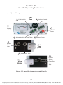
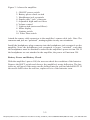
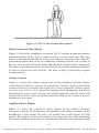
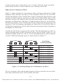
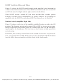
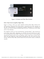
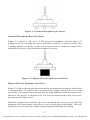
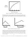
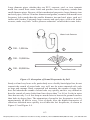
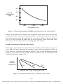
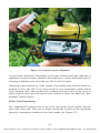
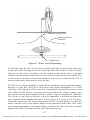
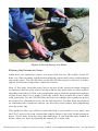
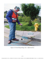
Table of Contents
Section
Section I.Sensor Damage and Personal Safety Precautions
1-1
Section II. Components, Standard Accessories
& Optional Accessories
2-1
Section III.Specific Operating Instructions
Assembly and Set-up
Battery Power and Battery Check
Hand Switch and Mute Button
Volume Control
Amplifier Meter Display
High and Low Frequency Filters
LIGHT Switch for Meter and Filters
Limitter Switch (Amplifier Side)
Filter-Thru Switch (Amplifier Side)
Ground Microphone Base for Streets
Magnet Base for Hydrants and Valves
Contact Rod for Soil and Brass Valves
3-1
3-1
3-2
3-3
3-3
3-3
3-4
3-5
3-5
3-6
3-7
3-7
3-8
Section IV.
4-1
4-1
4-1
4-4
4-5
4-6
4-8
General Strategies for Water Leak Detection
Types of Water Leak Sounds
Factors Affecting Leak Sounds
Sound Transmission Through Pipe Walls
Water Leak Surveys
Water Leak Pinpointing
Filtering Out Extraneous Noises
Section V.Specifications
5-1
Section VI. Warranty Statement
Returns for Repair and Replacement Parts
6-1
6-1
i
[email protected] | 13309 Beach Ave. Marina del Rey, CA 90292 | Phone: 800-WCT-PROD (800-928-7763) | Fax: 310-306-9343
List of Figures
Figure
3-1
3-2 3-3
3-4
3-5
3-6
Title
Amplifier Connectors & Controls
LD-12 with Ground Microphone
Listening Ranges for Combinations of Filters
Limitter and Filter-Thru Switches
Ground Microphone for Streets
Magnet Base for Hydrants & Valves
4-1
Sound Intensity vs. Water Pressure Graph
4-2
Filtered Frequencies Graphs
4-3
Absorption of Sound Frequencies by Soil
4-4
Sound Attenuation of Different Frequencies
by 4 feet of Soil
4-5
Sound Transmission vs. Distance from Leak
4-6
Leak Survey at a Hydrant
4-7
Water Leak Pinpointing
4-8
Leak Survey at a Meter
4-9
Leak Pinpointing Over a Hydrant Line
Page
3-1
3-3
3-4
3-6
3-7
3-7
4-2
4-2
4-3
4-4
4-4
4-6
4-7
4-8
4-9
ii
[email protected] | 13309 Beach Ave. Marina del Rey, CA 90292 | Phone: 800-WCT-PROD (800-928-7763) | Fax: 310-306-9343
Section I
Sensor Damage and Personal Safety Precautions
Warning!
The LD-12 can damage human hearing if it is used improperly. Always follow
these procedures for safe use:
1.Turn the amplifier volume down to twenty-five percent (25%) or
less before putting on the headphones.
2.Position the ground microphone (or sensor with magnet base)
firmly on the street or other listening surface before depressing the
mute switch.
3.Keep the ground microphone (or sensor with magnet base) and
the cable wires completely stationary whenever the mute switch is
depressed.
4.Turn up the amplifier volume to higher levels only when everything is stationary and the mute switch is depressed.
5.Release the mute switch before moving the ground microphone (or
sensor with magnet base) or before attaching hydrant wrenches,
valve keys, or other tools to the piping system.
Warning!
The LD-12 sensor inside the ground microphone is a ceramic piezo-electric
element. It can be broken if it is dropped onto concrete or other hard surfaces
from only 18 to 24 inches or if it is physically shocked in some other way. If the
piezo-electric element is broken due to harsh treatment, it must be replaced at the
owner's expense, and it will not be covered under the LD-12's warranty. The LD12 sensor is covered under the LD-12's warranty against manufacturing defects
and against failures during ordinary use and handling.
1-1
[email protected] | 13309 Beach Ave. Marina del Rey, CA 90292 | Phone: 800-WCT-PROD (800-928-7763) | Fax: 310-306-9343
Section II
Components, Standard Accessories & Optional Accessories
The LD-12 consists of the following component items and standard accessories:
1.Ground microphone and handswitch (mute) with three (3) pronged
base and forty (40) inch long sensor cable
2.Amplifier with power switch, volume control, meter display of sound
intensity (and battery power), adjustable low and high frequency filters, Limitter switch, Filter-Thru switch, and Lights switch.
3.Stereo headphones
4.Magnet base accessory
5.Three (3) section contact rod accessory
6.Ten millimeter (10mm) nutdriver for removing the base of the
ground microphone
7.Durable, water-tight carrying case with custom foam interior
8.Shoulder (or neck) strap for the amplifier
9.Padded carrying case for the amplifier
10. Instruction manual
Two optional accessories available for the LD-12 are:
1.Ground microphone with three (3) pronged base, handswitch, and
six (6) foot long sensor cable
2.Ground microphone with three (3) pronged base, handswitch, and
ten (10) foot long sensor cable
The longer sensor cables are used for lowering the sensor with the magnet base
down onto deep valves in water lines that are 5 to 10 feet deep.
Note: The sensor and cables are waterproof, allowing them to be lowered onto a
valve which is underwater.
2-1
[email protected] | 13309 Beach Ave. Marina del Rey, CA 90292 | Phone: 800-WCT-PROD (800-928-7763) | Fax: 310-306-9343
Section III.
Specific Operating Instructions
Assembly and Set-up
7 Light Switch
Top
View
6 Volume Control
8
Meter
Display
1
ON/OFF
Power
5
Adjustable High & Low Filters
2 Battery Power
4
Sensor
Cable
Jack
Side
View
(Left)
3 Headphone Jack
9
Limitter
Switch
Side
View
(Right)
Filter-Thru
Switch
10
Figure 3-1 Amplifier Connectors and Controls
3-1
[email protected] | 13309 Beach Ave. Marina del Rey, CA 90292 | Phone: 800-WCT-PROD (800-928-7763) | Fax: 310-306-9343
Figure 3-1 shows the amplifier:
1. ON/OFF power switch
2. Battery power check switch
3. Headphones jack receptacle
4. Sensor cable “jack” connector
5. Adjustable high and low filters
6. Volume control
7. Light switch (meter and filters)
8. Meter display
9. Limitter switch
10. Filter-Thru switch
Attach the sensor cable connector to the amplifier’s sensor cable jack. Note: The
connector and jack are “polarized”, mating together in only one orientation.
Install the headphones plug connector into the headphones jack receptacle on the
amplifier. Note: the headphones jack receptacle is power “switched”, such that
the headphones must be attached in order for the amplifier's power to turn ON. If
the headphones are not attached to the amplifier, the power will not turn ON.
Battery Power and Battery Check
With the amplifier’s power ON, the user can check the condition of the batteries.
Depress the BATT switch and observe the amplifier’s meter deflection. The batteries are still good if the meter needle deflects into the red line labeled BATT. If
the needle falls below the red line, replace all six of the batteries soon.
3-2
[email protected] | 13309 Beach Ave. Marina del Rey, CA 90292 | Phone: 800-WCT-PROD (800-928-7763) | Fax: 310-306-9343
Figure 3-2 LD-12 with Ground Microphone
Hand Switch and Mute Button
Figure 3-2 shows the completely assembled LD-12 with the ground microphone
positioned firmly on the street's surface directly over the water line. The mute
button in the handswitch shown in the user's hand is depressed only when the
ground microphone and cables are completely stationary and the user is ready to
hear the leak. Sound will not be heard until the mute switch button is depressed.
The mute switch button must be released before moving the ground microphone
in order to protect the user's hearing. The mute switch is specifically designed
for this purpose.
Volume Control
Figure 3-1 shows the volume control knob on the amplifier. Turn the volume
control knob clockwise to increase the sound level. Turn the volume control knob
counter-clockwise to decrease the sound level. Always adjust the volume control
to a low level (10% to 25%) when first putting on the headphones and before
depressing the mute switch. Increase the volume gradually until the water leak
sounds can be heard easily but without distortion. Reduce the volume if there is
distortion of the sound.
Amplifier Meter Display
Figure 3-1 shows the amplifier’s meter display of the sound’s intensity.
The meter’s display of the intensity corresponds to the sound’s loudness in the
headphones: a low display for quiet, soft sounds and a high display for loud
sounds. The purpose of the meter display is to assist the user when comparing
the sound’s intensity when the user’s hearing has difficulty distinguishing which
3-3
[email protected] | 13309 Beach Ave. Marina del Rey, CA 90292 | Phone: 800-WCT-PROD (800-928-7763) | Fax: 310-306-9343
location (on the street, at the meters, etc.) is louder. Often the meter can distinguish which location is louder when the user’s hearing can not tell.
High and Low Frequency Filters
Figure 3-1 shows the three (3) low frequency filter switches and the three (3) high
frequency filter switches. The three (3) low frequency filters are set at 100 Hz,
200 Hz and 400 Hz. If the 100 Hz filter switch is depressed, then all noises and
sounds at 100 Hz frequency and lower are filtered out. If the 200 Hz filter or 400
Hz filter switches are selected, then all noises and sounds at these frequencies
and lower are filtered out. The three (3) high frequency filters are set at 600 Hz,
800 Hz and 1200 Hz. If the 1200 Hz filter switch is depressed, then all noises and
sounds at 1200 Hz frequency and higher are filtered out. If the 800 Hz filter or
600 Hz filter switches are selected, then all noises and sounds at these frequencies
and higher are filtered out.
Usually the 100 Hz low frequency filter and the 1200 Hz high frequency filter are
selected initially until specific extraneous noises, such as traffic, wind, etc., are
identified audibly by the user. The six (6) low and high frequency filters combine
to allow 9 different listening ranges as shown below in Figure 3-3.
HIGH
LOW
100
200
400
600
800
1200
Leak Noise
Listening Range
100 Hz to 600 Hz
100 Hz to 800 Hz
100 Hz to 1200 Hz
200 Hz to 600 Hz
200 Hz to 800 Hz
200 Hz to 1200 Hz
400 Hz to 600 Hz
400 Hz to 800 Hz
400 Hz to 1200 Hz
Figure 3-3 Listening Ranges for Combinations of Filters
The low frequency filter and the high frequency filter can often be used to eliminate many extraneous noises such as traffic and wind.
3-4
[email protected] | 13309 Beach Ave. Marina del Rey, CA 90292 | Phone: 800-WCT-PROD (800-928-7763) | Fax: 310-306-9343
LIGHT Switch for Meter and Filters
Figure 3-1 shows the LIGHT switch located on the amplifier’s face between the
volume control knob and the meter. The LIGHT switch allows the user to turn ON
or OFF the meter backlight and the light switches for the filters.
If the LIGHT switch is turned OFF, the meter and the filter switches operate
normally, but their power consumptions are greatly reduced. By operating the
amplifier with the LIGHT switch turned OFF, the battery lives are doubled.
Limitter Switch (Amplifier Right Side)
Figure 3-4 shows a side view of the amplifier with the Limitter switch in the ON
position. The Limitter switch can be turned ON or OFF by the user at any time.
In the ON position, the Limitter stops any sound louder than 110 dB from passing through to the headphones. The user can use the Limitter to fully protect his
or her hearing.
Sometimes, the user may wish to listen to the sounds of a leak at a very loud volume, even greater than 110 dB. In this case, the user should turn OFF the Limitter
in order that it does not interfere with the clarity of the loud sounds.
3-5
[email protected] | 13309 Beach Ave. Marina del Rey, CA 90292 | Phone: 800-WCT-PROD (800-928-7763) | Fax: 310-306-9343
Figure 3-4 Limitter and Filter-Thru Switches
Filter-Thru Switch (Amplifier Right Side)
Figure 3-4 shows a side view of the amplifier with the Filter-Thru switch in the
OFF position. When the Filter-Thru switch is turned ON, the filter switches on
the face of the amplifier are completely by-passed, and there is no filtering of
sounds at all. The user hears all sounds from 50 Hz to 15,000 Hz (or to the extent
of his or her hearing).
The amplifier’s filters are most useful during “ground miking”, when extraneous
noises from wind, traffic, equipment, etc. interfere the most with the user’s ability to distinguish the leak sounds. Often these extraneous noises are not troubling
interferences during leak surveys at hydrants, meters, and valves. At these locations, the leak sounds are easily heard, and often the user will wish to do leak
surveys with the Filter-Thru switch turned ON (to hear the clearest, un-filtered
sounds).
3-6
[email protected] | 13309 Beach Ave. Marina del Rey, CA 90292 | Phone: 800-WCT-PROD (800-928-7763) | Fax: 310-306-9343
Figure 3-5 Ground Microphone for Streets
Ground Microphone Base for Streets
Figure 3-5 shows a side view of the ground microphone with the three (3)
pronged base for listening on streets, pavement surfaces, or concrete slabs. The
3 prongs should rest firmly on the street's hard surface in order for sound to be
transmitted clearly to the ground microphone's sensor.
Figure 3-6 Magnet Base for Hydrants and Valves
Magnet Base for Hydrants and Valves
Figure 3-6 shows the magnet base attached to the ground microphone without the
3- pronged base. To remove the 3-pronged base, simply unscrew the base from
the sensor. The magnet base should only be hand-tightened onto the brass screw
thread of the sensor. It should not be left loosely attached since this will create
movement and slight noises.
With the magnet base attached, the user can attach the sensor to cast iron fire
hydrants, iron water mains, iron valves, or steel water pipes and fittings. This will
enable the user to hear the sounds being transmitted through the piping.
3-7
[email protected] | 13309 Beach Ave. Marina del Rey, CA 90292 | Phone: 800-WCT-PROD (800-928-7763) | Fax: 310-306-9343
Contact Rod for Soil and Brass Valves
The contact rod is provided to assist in contacting the sensor to materials that
are soft, spongy, porous, or non-ferrous. To use, remove the nut on the base of
the ground microphone with the nutdriver and attach the contact rod to the brass
thread. If only a short rod is needed, attach only the pointed section of the contact rod to the bottom of the sensor. For deep brass valves at curb stops, use all
three (3) sections of the contact rod, and push the point of the contact rod firmly
against the brass valve. For water leak searches in areas covered by loose soil or
grass cover over the water line, use only the pointed bottom section of the contact
rod.
In either application, do not try to hold the sensor or the contact rod with your
hand, since this will cause small movements and "crackling" sounds at the point
of contact of the rod. Let the sensor or the contact rod rest against the curb box
wall or the meter box wall. For water leak searches in areas covered by loose soil
or grass, push the pointed contact rod firmly into the dirt two to six inches, but do
not hammer it into the ground or try to force it in deeply. It only needs to make
firm contact in the ground.
Warning!
The sensor and the contact rod are not a digging tool, boring bar, or other heavy
tool. Use these other tools for pushing through the soil or digging holes, and do
not risk damaging the ceramic element inside the sensor by using the contact rod
in this manner.
3-8
[email protected] | 13309 Beach Ave. Marina del Rey, CA 90292 | Phone: 800-WCT-PROD (800-928-7763) | Fax: 310-306-9343
Section IV
General Strategies for Water Leak Detection
Types of Water Leak Sounds
There are three different, commonly identified sounds produced by water leaks:
1.Pipe resonance and vibration from orifice pressure reduction.
2.Water impaction on the surrounding soil.
3.Water circulation and flow in the surrounding soil cavity.
Resonance or pipe vibration is often the loudest or most intense leak noise, sounding like a "whoosh" or a "hiss." Water impaction and circulation are often weaker,
and often they may only be heard when the LD-12 user is very close to the leak
or directly over it. Water impacting directly on the soil is a "beating" or a rapid
"thumping" sound, and water flowing into the soil and around the pipe sounds like
a "babbling brook" or a mountain stream. If the leak has created a very large cavity
in the soil, these second and third sounds may not be heard at all.
Factors Affecting Leak Sounds
There are several factors that affect the loudness and the frequency range of
sounds made by water leaks in water pipes and transmitted to the surface of the
ground. These factors are:
1.Water pressure in the pipe (must be 25 psi or more)*
2.Pipe material and pipe diameter
3.Soil type and soil compaction
4.Depth of soil over the pipe
5.Surface cover: grass, loose soil, asphalt, concrete slab, etc.
* Pressuring to 50-60 psi or more will greatly aide detection. The intensity
or loudness of water leak sounds increases greatly with increasing water
pressure (see Figure 4-1).
4-1
[email protected] | 13309 Beach Ave. Marina del Rey, CA 90292 | Phone: 800-WCT-PROD (800-928-7763) | Fax: 310-306-9343
Sound
Intensity
(Amplitude)
15
30
45
60
75
Water Pressure (psi)
Figure 4-1 Sound Intensity vs. Water Pressure Graph
Metal pipes, such as iron mains, copper services, and steel pipes, transmit water
leak sounds that are louder and higher in frequency than do PVC pipes or asbestos-cement pipes. Thus, knowledge of the pipe material is important (see Figure
4-2).
200
600
Leak noise range
for PVC Pipe
Hertz
400
1000 Hertz
Leak noise range
for Cast Iron Pipe
Figure 4-2 Filtered Frequencies Graphs
If the LD-12 user knows that the leak is small, with pressure of 60 psi or more,
and in an iron main or copper service, then the user knows the sounds should be
in a high frequency range, perhaps 400 Hz to 1200 Hz. If the LD-12 user knows
that the leak is large, with a pressure of only 30 to 40 psi, and in a PVC pipe,
then the user knows the sounds should be in a lower frequency range, perhaps
200 Hz to 600 Hz.
4-2
[email protected] | 13309 Beach Ave. Marina del Rey, CA 90292 | Phone: 800-WCT-PROD (800-928-7763) | Fax: 310-306-9343
Large diameter pipes, whether they are PVC, concrete, steel, or iron, transmit
much less sound from water leaks and produce lower frequency sounds than
small diameter pipes. Because of their mechanical properties, large diameter iron
and steel pipes, such as 24 inches diameter and greater, resonate with much lower
frequency leak sounds than the smaller diameter iron and steel pipes, such as 6
inches and 8 inches. Extremely large concrete and steel pipes, such as 96 inches
or more, make very little "orifice pressure reduction" sound at their water leaks.
Water Leak Detector
C
100 - 1,000 Hz
B
100 - 10,000 Hz
A
100 - 20,000 Hz
C
B
A
Water Leak
Figure 4-3 Absorption of Sound Frequencies by Soil
Sandy soil and very loose soils, particularly over a freshly buried pipe line, do not
transmit the sounds of water leaks very well, nor do water saturated soils such
as bogs and swamps. Hard, compacted soil transmits the sounds of water leaks
best. Soil absorbs the sounds of water leaks very quickly, and it is very difficult to
hear the sounds of water leaks from lines deeper than 7 or 8 feet. Leaks in water
lines that are only 3 or 4 feet deep are much easier to hear at the ground's surface
than leaks in deeper lines. The attenuation of sound in low frequencies in soil is
approximately 40 dB for every 3 feet of depth. Also, the higher frequencies of
sound are absorbed more quickly in soil than the low frequencies, as shown in
Figure 4-3 and Figure 4-4.
4-3
[email protected] | 13309 Beach Ave. Marina del Rey, CA 90292 | Phone: 800-WCT-PROD (800-928-7763) | Fax: 310-306-9343
-20
Sound
Attenuation
(dB)
-40
-60
-80
200
1,000
5,000
Frequency (Hz)
Figure 4-4 Sound Attenuation of Different Frequencies by 4 feet of Soil
Finally, the ground cover, whether it is an asphalt street, loose dirt, concrete slab,
or grass lawn, also makes an important difference. Hard street surfaces and concrete slabs resonate with the sounds of the water leak, and the leak may be heard
for 5 to 10 feet or more on either side of the water pipe. Grass lawns and loose
dirt surfaces do not offer such a resonating plate-like surface.
Sound Transmission Through Pipe Walls
Metal pipes, particularly iron mains between 6 inches and 12 inches, copper services, and steel pipes, transmit the sounds of water leaks for hundreds of feet in
every direction. Asbestos-cement pipe and PVC pipe do not transmit the sounds
nearly as far, and the sounds of leaks in these materials may be transmitted only
100 to 400 feet (see Figure 4-5).
Sound
Intensity
(Amplitude)
PVC
ACP
CIP
Distance from Leak, Axially along Pipe
Pipe Material
Transmitted Frequencies
PVC
100 - 10,000 Hz
Figure 4-5Cast
Sound
vs.- Distance
IronTransmission
100
20,000 Hzfrom Leak
4-4
[email protected] | 13309 Beach Ave. Marina del Rey, CA 90292 | Phone: 800-WCT-PROD (800-928-7763) | Fax: 310-306-9343
Distances transmitted for the sounds of water leaks are a function of the pipe
diameter as well as the pipe material (see table below).
Pipe Material and Diameter
Typical Max. Distance for
Transmission of Leak Sounds
6 inch Cast Iron Pipe
12 inch Cast Iron Pipe
24 inch Cast Iron Pipe
6 inch AC Pipe
12 inch AC Pipe
24 inch AC Pipe
6 inch PVC Pipe
12 inch PVC Pipe
24 inch PVC Pipe
600 to 1000 feet
400 to 800 feet
200 to 400 feet
400 to 800 feet
300 to 500 feet
100 to 300 feet
200 to 300 feet
100 to 200 feet
50 to 100 feet
Thus knowledge of the pipe material and diameter is important to knowing how
far the sounds of a leak may be transmitted along the pipe walls. If the leak is in
a 6 inch cast iron water line, the LD-12 user will listen first at the hydrants and
main valves. If the LD-12 user hears nothing at the first location, he moves 500
to 600 feet to another hydrant or main valve. If the leak is in a 24 inch PVC pipe
however, the LD-12 user cannot simply listen at only hydrants and main valves
and be assured that there are no leaks within 500 to 600 feet. In this case, the LD12 user must check at every possible curb stop and valve, or the user may even
“ground mike” the entire length of the 24 inch PVC pipe.
Water Leak Surveys
If there is no obvious evidence of a major water leak, like water surfacing or very
loud leak sounds at the hydrants, but the area is experiencing abnormally large
water losses, then a "water leak survey" may be needed. The water leak survey is
usually done with only the magnet base attached to the sensor, and it initially is
conducted only at the hydrants and the main valves (see Figure 4-6).
4-5
[email protected] | 13309 Beach Ave. Marina del Rey, CA 90292 | Phone: 800-WCT-PROD (800-928-7763) | Fax: 310-306-9343
Figure 4-6 Leak Survey at a Hydrant
As previously discussed, knowledge of the pipe material and pipe diameter is
important in order to know whether a thorough survey can be performed only by
listening at hydrants and valves that are 500 to 600 feet apart.
During the water leak survey, if the sounds of a possible water leak are heard at a
hydrant or valve, the LD-12 user then checks at every immediate, nearby lateral
valve, hydrant valve, and residential or commercial service line. At the valve or
other location where the leak sound is the loudest is where the final leak "pinpointing" usually begins.
Water Leak Pinpointing
The "pinpointed" location refers to the exact spot on the street's surface directly
above the water leak. This spot is almost always the location of the maximum
intensity or maximum loudness of the leak sounds (see Figure 4-7).
4-6
[email protected] | 13309 Beach Ave. Marina del Rey, CA 90292 | Phone: 800-WCT-PROD (800-928-7763) | Fax: 310-306-9343
Maximum leak noises
Rapid attenuation
of noises
Water Leak
Figure 4-7 Water Leak Pinpointing
To find this spot, the LD-12 user must carefully mark the location of the water line
on the street after locating it exactly with a pipe and cable locator. Usually, the piping between the valve or hydrant with the loudest sound and the valve or hydrant
with the second loudest sound is the section of the line that needs to be marked. The
section must be accurately located and marked on the street in order for the LD-12
user to consistently listen directly over the line.
The LD-12 user listens with the 3-pronged base attached to the ground microphone
directly over the line. The LD-12 user moves the ground microphone 3 to 4 feet
each time in the direction of the water line, listening and moving closer to the water
leak. While the LD-12 user is moving, he does not adjust the volume control, since
the volume must be held constant in order to make accurate comparisons. When the
LD-12 user is very close to the leak, it may be impossible to decide based upon the
user’s hearing alone whether the leak is in one spot or is in a spot 3 to 4 feet away.
When this occurs, the LD-12 user must study the LD-12 meter display. Usually, the
meter’s needle will be just slightly higher at one spot than at the other. This is the
most important purpose of the meter display, allowing the LD-12 user to accurately
pinpoint the leak’s location when the user’s hearing can not.
4-7
[email protected] | 13309 Beach Ave. Marina del Rey, CA 90292 | Phone: 800-WCT-PROD (800-928-7763) | Fax: 310-306-9343
Figure 4-8 Leak Survey at a Meter
Filtering Out Extraneous Noises
Often there are extraneous noises at a water leak job site, like traffic, wind, AC
hum, etc., that can make leak detection difficult, particularly water leak pinpointing on the street. The 200 Hz filter or the 400 Hz filter may be effective at reducing the interference from these extraneous noises.
Step 15 feet away from the water line to an area of the street pavement identical
in surface to that over the water line but without any water lines or other utilities
anywhere beneath it. Listen to the extraneous noises with the ground microphone
on the street, and if it is windy, block the wind's flow around the sensor cable
with your body. Try the 200 Hz filter and listen to whether the extraneous noises
are reduced or eliminated; if not, try the 400 Hz filter. If either filter has reduced
or eliminated the extraneous noises, use that filter and resume leak pinpointing
over the water line.
This method is also very effective when the leak is very small, or very quiet, and
the LD-12 user is not even certain that what he hears is the leak. In this situation,
move 15 feet away from the water line and listen. If you hear the same sounds as
before, then you were not hearing the sounds of a water leak.
4-8
[email protected] | 13309 Beach Ave. Marina del Rey, CA 90292 | Phone: 800-WCT-PROD (800-928-7763) | Fax: 310-306-9343
Figure 4-9 Leak Pinpointing Over a Hydrant Line
4-9
[email protected] | 13309 Beach Ave. Marina del Rey, CA 90292 | Phone: 800-WCT-PROD (800-928-7763) | Fax: 310-306-9343
Section V
Specifications
Amplifier
• Input Impedance
: 50k ohms
• Output Impedance : 15 ohms
• Amplification
: 62 dB +/- 3dB
• Frequency Range
: 1) 100Hz to 1200Hz
(13 dB) with Filter-Thru OFF
2) 15Hz to 30,000Hz
(13 dB) with Filter-Thru ON
• Power : 6 AA dry cell batteries
• Power Consumption : 1) 70 mA or less with backlight ON
2) 35 mA or less with backlight OFF
• Battery Life
: 1) 28 hours with backlight OFF
(alkaline cells)
2) 14 hours with backlight ON
(alkaline cells)
• Weight : 31 ounces (885 g)
• Size
: 6.7" x 2.8" x 4.1"
(170mm x 70mm x 103mm)
ABS Carrying Case
• Weight (full)
: 15 lb. (6.81 Kg)
• Size
: 18.5" x 14.6" x 7.5"
(470mm x 371mm x 190mm)
5-1
[email protected] | 13309 Beach Ave. Marina del Rey, CA 90292 | Phone: 800-WCT-PROD (800-928-7763) | Fax: 310-306-9343
Section VI
Warranty Statement
SubSurface Leak Detection, Inc. (SubSurface) warrants each product of its
manufacture to be free from defects in material and workmanship subject to the
following terms and conditions. The warranty is effective for sixty months after
shipment by SubSurface to the original purchaser.
Our obligation under the warranty is limited to servicing or adjusting any product
returned to the factory for this purpose and to replace any defective part thereof.
Such product must be returned by the original purchaser, transportation charges
prepaid, with proof in writing, to our satisfaction, of the defect. If the fault has
been caused by misuse or abnormal conditions of operation, repairs will be billed
at cost. Prior to repair in this instance, a cost estimate will be submitted. Service
or shipping information will be furnished upon notification of the difficulty
encountered. Model and serial numbers must be supplied by user. Batteries are
specifically excluded under the warranty.
SubSurface shall not be liable for any injury to persons, or property, or for any
other special or consequential damages sustained, or expenses incurred by reason
of the use of any SubSurface product.
Returns for Repair and Replacement Parts
For service or repair
please contact distributor:
Toll-Free:
Local Phone:
Fax:
Email:
Address:
Website:
800-WCT-PROD (928-7763)
310-822-5212
310-306-9343
[email protected]
13309 Beach Ave.
Marina del Rey, CA 90292
www.wctproducts.com
January 2006
6-1
[email protected] | 13309 Beach Ave. Marina del Rey, CA 90292 | Phone: 800-WCT-PROD (800-928-7763) | Fax: 310-306-9343