1
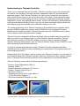
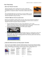
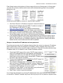
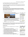
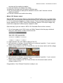
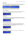
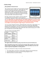
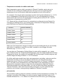
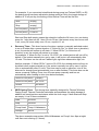
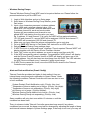
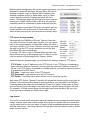
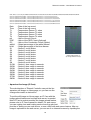
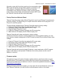
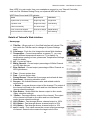
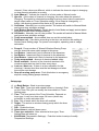
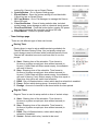
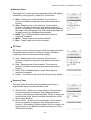
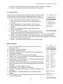
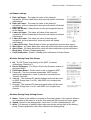
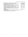
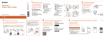
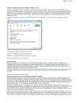
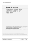
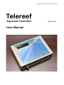
Telereef Controller - User Manual V.140313!
!
Telereef
Aquarium Controller
User Manual
1
Model: TR1D
Telereef Controller - User Manual V.140313!
Telereef Controller - User Manual
!
Table of contents
!
Understand your Telereef Controller!
3!
First Time Setup!
4!
Mount the Telereef Controller!
Obtain IP Address and set up system time!
Understand Web Interface and Setup System Time/Date!
Setup an internal fixed IP address and new password!
Setup Temperature Probe!
Setup pH Probe!
Adjust 10V dimmer output!
LCD Display!
4!
4!
4!
5!
6!
6!
7!
8!
Date and Time page!
Sensors Page!
Dimmers & Sockets status page !
System information!
8!
8!
8!
8!
Further Setup!
9!
Relay Module & Socket Panels!
Temperature controller for chiller and heater!
pH controller!
Timers!
Wireless Dosing Pumps!
Alert and Push notification (Prowl / Notify)!
Settings Export/Import and Micro SD Memory!
FTP server for logs backup!
Log format!
Aquarium live image (IP Cam)!
Trusted IP!
Wireless Network Connection!
Factory Reset and Network Reset!
Firmware update!
If problem persists, please contact us at [email protected] for help.!
Set WDP in pair mode!
Details of Telereef’s Web interface!
9!
10!
10!
11!
13!
13!
14!
15!
15!
16!
17!
17!
18!
18!
19!
19!
20!
Home page!
Setup page!
Timer Settings page!
System settings!
Socket name settings!
Temperature settings!
pH Sensor settings!
Wireless Dosing Pump Pair Screen!
Wireless Dosing Pump Setting Screen!
20!
21!
23!
25!
26!
26!
27!
27!
27!
2
Telereef Controller - User Manual V.140313!
Understand your Telereef Controller!
!
Thank you for choosing Telereef Controller. Telereef Controller is a low cost but powerful
and easy to use aquarium controller, specially designed for both DIY and professional
aquarium projects. With Telereef Controller, you can control and monitor your aquarium
with a Smart Phone even you are on the other side of the planet. Timer schedules setup,
brightness control of LED lighting, pH value monitoring, temperature monitoring, precise
temperature control (with optional relay sockets), electric cost estimation, dosing additives
(with optional Wireless Dosing Pump), even you can know how much additive remains for
each dosing pump and provides push notification remind you to refill.
!
The central processing unit of Telereef Controller is ATmega2560 micro controller which
provides 256KB programming memory and 8K SRAM for running Telereef Firmware.
Beside these on board memories, Telereef Controller also has a 2GB SD memory which
used to keeps sensors logs and system settings.
!
Telereef Controller integrated with Ethernet Module which provides network connectivity,
able to connect to any existing router out of box. Beside network connectivity, Telereef
Controller also provides 2.4GHz RF wireless connectivity, able to connect to Telereef
Wireless Devices totally freedom, such as Telereef Wireless Dosing Pump TRWDP-S1 and
other upcoming Telereef Wireless Devices.
!
To achieve accurate and stable pH reading, Telereef Controller integrated with Atlas
Scientific pH Circuit which provides continually pH measurement to the aquarium with one
touch calibrating feature.
!
Please follow “First Time Setup” section to setup your Telereef Controller. You may need to
do a Network Reset if the Telereef Controller was ever connected to other network, please
refer to “Network Reset and Factory Reset” section about how to do a Network Reset.
!
Telereef Controller comes with the following accessories
!
- Dimmer Voltage Adjustment Cable x 1
- Network Cable x 1
- Small Screwdriver for Dimmer 10V Trim x 1
- System / Network Reset Plug x 1
- pH Sensor Probe x 1
- Temperature Sensor with 3 meter cable x 1
- 12V 2A DC Power Adapter x 1
- Self-Stick Reclosable Fasteners x 1 pair
!
!
*Life time update - We will provide firmware update as long as the product is still selling in market.
3
Telereef Controller - User Manual V.140313!
First Time Setup!
!
• Mount the Telereef Controller!
!
Telereef Controller comes together with one pair of Self-Stick
Reclosable Fasteners, you can use it to mount Telereef Controller
somewhere on aquarium cabinet. Clean both surfaces before stick it
on.
!
This reclosable fasteners is very strong, you may consider to cut it
into two small pieces and stick them on two corners on the back of
Telereef Controller for easy removing.
!
• Obtain IP Address and set up system time!
!
!
Because of simplified no button design, the only way to set up Telereef Controller is
through the Telereef’s Web Interface. First thing to do is find out how to connect to
Telereef Controller through the network connection.
1. Connect Telereef’s LAN port to one of the LAN ports on your router. (Telereef Controller can be connected wirelessly by using a small Traveller Nano
Router, please refer to Wireless Connection section for details.)
2. Connect Telereef’s DC port to a 12V 2A DC power adapter.
!
3. After connected DC power the LCD backlight will light up, and firmware version will
be displayed, now Telereef Controller is trying to obtains an IP address from the
router, the IP address will be displayed after a few seconds, please write down this
IP address for future use.
!
!
• Understand Web Interface and Setup System Time/Date!
There are two main pages on Telereef’s Web Interface, they are Home page and Setup
page. Home page is used to present sensors information, socket status, socket manual
on/off, wireless dosing pump status, manual dosing control, usage statistic, etc.
4
Telereef Controller - User Manual V.140313!
Push Setup button at the bottom of Home page will move to Setup page. In Setup page
you can set up timers, define socket name, pair wireless dosing pump, set up system
preference, etc.
Follow the below steps to connect to Telereef Web Interface
!
!
!
!
1. Use Smart Phone’s or Desktop computer’s Internet browser to
browse the IP address with port 8085. For above example, if
the IP address is 192.168.2.12, input http://192.168.2.12:8085 to the browser's address bar.
2. User Name & Password screen will display, input default user
name “user" and default password “user" (without quotes).
3. Scroll down to bottom of the Home page, push Setup button.
On the Setup page, scroll down to the end and push System button.
4. In the System page there are many things can be set, first thing we need to set is
System Date and Time. The System Date and Time fields are automatically filled
with your Smart Phone’s or Desktop computer’s date and time, simply push Save
button and the current date and time will be updated.
!
• Setup an internal fixed IP address and new password!
!
From the previous step, the IP address obtained from the router is a dynamic IP address,
which means that it may be changed or occupied by other computer from time to time,
there will be a chance you may be unable to connect to Telereef Controller with the same
IP address later, so it is better to use a fixed IP address instead.
!
1. Check the DHCP range of the router, DHCP range means a
range of IP address that the router assigns automatically; for
example 192.168.0.2 to 192.168.0.50. Usually the DHCP
range can be found inside router’s setup panel. Please refer to
the router user manual for details.
2. Choose an IP address which is outside the DHCP range, for
example 192.168.0.101
3. Go to System Settings page, change the field “IP address”
with the chosen IP Address on step #2, change “Subnet Mask”
if necessary, default is 255.255.255.0, change the “Gateway”
to router’s LAN IP address if it is not correct.
4. Change the “User Name” to the login name you preferred and
change the “Password” to a new password.
5. Push “Save” button to save the settings.
If you forgot the password or a wrong IP address has been used then you may not able
to connect to Telereef Controller any more, the only way to fix it is perform a system reset
5
Telereef Controller - User Manual V.140313!
!
by using the reset plug on P1 or P2 port; however, all settings will be erased. Please
refer to Factory Reset and network reset section for details.
To connect Telereef Controller from outside network through Internet, Port Forwarding or
Virtual Server is needed to be setup on the router on TCP port 8085, please refer to the
router manual for details.
!
• Setup Temperature Probe!
There is a temperature sensor on Telereef main board; it used to report the internal
temperature of Telereef Controller to prevents overheating problem. The temperature
which is display on Home page is referred to the internal temperature sensor before an
external temperature probe has been setup.
!
To setup external temperature probe
a.
b.
Unplug the DC power from Telereef Controller
Plugin external temperature sensor to the three pins “T” port,
reconnect the DC power and wait for Telereef started up.
!
c.
d.
e.
!
f.
!
On Setup page, push “Edit” on Temperature Settings section.
At “T1 Sensor” select the address of the external temperature
sensor, if the address is not inside the pull down menu,
please reload this Temperature Settings page and try again.
At “T2 Sensor” select the address of the internal temperature
sensor.
Push “Save” button to save the settings.
Now, the big temperature reading on Home page changed shows the temperature of the
external temperature sensor. The temperature of internal temperature sensor can also
be found at the Sensors section of Home page.
• Setup pH Probe!
A new pH probe need to be calibrated before use. To calibrate a
pH probe
!
1. Connect the pH probe to the Probe port
2. On Home page, make sure the pH value is not “N/A” (N/A
means AtlasScientific pH stamp is not installed).
3. Go to Setup page and scroll down to pH Sensor Settings
4. Raise the pH probe with RO water or Distilled water.
5. Dry the probe and put inside pH7 calibration solution, wait 2
minutes until the reading is stabled.
6. Push pH7 button and confirm the setting.
7. Raise the pH probe with RO water or Distilled water.
8. Dry the probe and put inside pH4 calibration solution, wait 2
6
Telereef Controller - User Manual V.140313!
!
minutes until the reading is stabled.
9. Push pH4 button and confirm the setting.
10. Raise the pH probe with RO water or Distilled water.
11. Dry the probe and put inside pH10 calibration solution, wait 2 minutes until the
reading is stabled.
12. Push pH10 button and confirm the setting.
• Adjust 10V dimmer output!
Telereef TR1D provides two dimming channels for LED dimmable driver (eg. Mean Well
ELN-60-48D), one for White LEDs and one for Blue LEDs. Two dimming channels output
0 - 10V to controls the brightness of each channel. These dimming channels have been
factory adjusted 10V at 100% output before shipping; however, the output voltage may
need to be readjusted if different power adapter is used.
(Skip this step if you don’t have a LED 0-10V Dimmable Driver at this moment)
!
1. Go to Home page, push 100% button on White Channel, after the page refreshed
then push 100% button on Blue channel as well.
!
2. Plugin Dimmer 10V Trim Cable to Dimmer Port “B”
3. Set multimeter to Voltage, connect Red line to multimeter’s positive “+” port, connect
Black line to multimeter’s negative “-” port.
4. Insert small screwdriver into 10V Trimer B hole, turn the screw inside until the voltage
reading is 10V.
!
!
5. Plugin Dimmer 10V Trim Cable to Dimmer Port “W”
6. Set multimeter to Voltage, connect Red line to multimeter’s positive “+” port, connect
Black line to multimeter’s negative “-” port.
7. Insert small screwdriver into 10V Trimer W hole, turn the screw inside until the
voltage reading is 10V
!
Congratulation ! Your Telereef Controller is ready to use.
!
7
Telereef Controller - User Manual V.140313!
LCD Display!
!
The LCD on Telereef Controller provides some useful information for both setup and daily
usage. When system starting, LCD shows model, firmware version and IP Address.
!
!
After system started, LCD cycling 4 pages with different information
!
• Date and Time page!
First page of LCD display shows system time and date. If the time or date is not correct,
please go to Setup page, push System button and update the time and date.
!
!
• Sensors Page!
Second page of LCD display shows three temperature probe reading and pH value. An
up “↑” arrow or down “↓” arrow indicates raising or lowering socket control is activated, or
"!" Indicates the value is out of safety range.
!
!
• Dimmers & Sockets status page !
Third page of LCD display shows current output level of two dimming channels and
status of eight relays/sockets. P1 is corresponding to relays/sockets S1 - S4, P2 is
corresponding to relays/sockets S5 - S8. Socket with status On has an indicator “ * ” on
it’s position, status Off has an indicator “-” instead.
!
!
• System information!
!
!
Last page of LCD display shows some system information, e.g. free memory, IP.., etc.
!
8
Telereef Controller - User Manual V.140313!
Further Setup
!
• Relay Module & Socket Panels!
Two 4-Channel relay modules can be connected to Telereef
Controller through P1 and P2 port, totally eight relays can
be use to control eight electrical devices. Most 5V 4Channel relay modules in the market which is compatible
with Arduino are also compatible with Telereef Controller.
There is 5V output from P1 and P2 port which can supply
relay module without external power supply.
Sainsmart 4-Channel 5V
Relay Board
Normally, this kind of relay module is good and safety for
low voltage DC devices, however if you are going to
connect high voltage AC or high power devices should be careful, such as chiller, heater,
etc. You should have enough knowledge, and related qualification to connect relay
module to AC powered device and should be very careful when connecting, good
isolated is also very important; otherwise, serious electrical shock or fire may
occur. Make sure the relay has enough rating to controls the device.
You can connect Telereef Controller to Relays/Sockets module with a signal cables. You
can purchase this cable from our reseller, or make it by yourself easily. Most Relay
Modules in the market have a six pins connector which is compatible with KF2510 plug,
just install six pins KF2510 plug on both ends of the cable, one end is plug into P1 or P2
port, the other end is into the relay module. The color coding of the signal cable is
Orange
+5V
White Orange
Ground
Green
Relay 1
White Green
Relay 2
Brown
Relay 3
White Brown
Relay 4
The signal cable should be keep away from AC line to prevent interference.
!
Some mechanical relays may not go back to off state after turned on for a long
period of time continually, you should beware of this especially if you use it to
control aquarium temperature or dosing device. Once your socket panel is ready, next step is setup socket name
!
1. Go to Setup page, scroll down to Socket Name Settings and push Edit button.
2. Input the Name of the device connected, Rating/Usage and Unit.
3. Push Save button to save the setting.
!
9
Telereef Controller - User Manual V.140313!
• Temperature controller for chiller and heater!
Each temperature sensor which connected to Telereef Controller can be set up to
controls it's own cooling and heating devices, the way to set up is defining what
temperature to turn on the device and what temperature to turn off the device. For example, if the target water temperature is 26°C, the fluctuate allowance is +/- 0.2°C,
turn on temperature of cooling device will be 26.2°C, turn off temperature of cooling
device will be 26°C and turn on temperature of heating device will be 25.8°C, turn off
temperature of heating device will be 26°C
If T1 Sensor will be use and Socket 2 is connecting to cooling device and Socket 3 is
connecting to heating device, go to Setup page, scroll down to Temperature Settings,
push Edit button and input the following settings
T1 Sensor
(Sensor address)
Heater Upper
26
Heater Lower
25.8
Heater Socket
S3
Chiller Upper
26.2
Chiller Lower
26
Chiller Socket
S2
Make sure the temperature ranges of cooling device and heating device are not overlap
each other. In case the on and off is too often, consider to use a bigger fluctuate
allowance (eg. +/- 0.3 or +/- 0.4)
!
You can also use Temperature Setting Wizard to setup all the ranges for you, simply
push “Wizard” button on Temperature Settings page, input the target temperature of each
Temperature Sensor, the system will calculates the Cooling range, Heating range as well
as Alert range according to default +/- 0.2°C fluctuation.
!
On chiller and heater usually have their own temperature controllers, make sure set the
temperature on them to one or two degree celsius more (or less) than the target
temperature set on Telereef Controller. If target temperature on Telereef Controller is
26°C, set chiller’s own temperature to 28°C and heater’s own temperature to 24°C.
Because this temperature range is larger than the temperature range that Telereef
Controller activates the chiller and heater, so it will not affect the normal operation of
Telereef Controller, it also works as secondary emergency cut off in case the relay
module is out of order or wrong setting is applied on Telereef Controller.
!
• pH controller!
The procedure used to setup pH controller is similar as setup temperature controller. For
example, controlling CO2 dosage in a calcium reactor, target internal pH value is 6.5,
fluctuate allowance is +/- 0.2, Socket 4 connected to the CO2 valve, go to Setup page,
10
Telereef Controller - User Manual V.140313!
scroll down to pH Sensor Settings, push Edit button and input the following settings
Lower pH Upper
6.7
Lower pH Lower
6.5
Lower pH Socket
S4
We don’t recommend to control aquarium pH by using this function, using pH controller
to add additives to aquarium is high risk since you never know how much amount of
additives will be added to the aquarium. According to the pH value and create a dosing
pump timer schedule for additive is recommended.
!
• Timers!
There are six different kinds of timer can be set up in Telereef Controller
!
a.
b.
Regular Timer : Turn on and turn off specific socket in specific time range, weekly
schedule can also be applied.
Dimming Timer: Change dimming channels output percentage at specific time. If
“Stop” field also be defined, a slow dimming effect will be applied. Weekly schedule
can also be applied.
For example, if initial output is 0% and the following is defined
Start
08:00:00
Stop
09:00:00
White
80
Blue
100
means both dimming channels will started to slow increasing from 0% at 8am and
reached to White Channel 80%, Blue Channel 100% at 9am
Another example, if initial output is 100%
Start
18:00:00
Stop
20:00:00
White
0
Blue
10
means both dimming channels started to slow decreasing from 100% at 6pm and
reached to White Channel 0% and Blue Channel 10% at 8pm, after 8pm only 10%
Blue light is remained, White light is turned off.
c.
!
Interval Timer : Within a time range, turn on specific socket for specific duration
and turn off specific interval time period. Weekly schedule can also be applied. This
kind of timer is useful for wave making pump or traditional dosing pump.
11
Telereef Controller - User Manual V.140313!
For example, if you connected a traditional dosing pump (not Telereef WDP) on S5,
the dosing pump has been adjusted a dosing speed at 1ml/s, the target dosage of
additive is 12 ml per day, the setting of this Interval Timer will be like this
Start
(empty)
Stop
(empty)
On Dur(ation)
00:00:01
Off Dur(ation)
01:59:59
Start and Stop both empty means the schedule is effective 24 hours, turn on dosing
pump for 1 sec then turn off 1 hour 59 min 59 sec, that means every two hours runs
1 sec, every 24 hours totally runs 12 sec, equal to 12 ml.
d.
!
Recovery Timer : This timer has two functions, restore a manually switched socket
to on or off state after a preset duration. If “Allow On Dur” (ie. Allow turn on duration)
is set, the socket will restore to off state. If “Allow Off Dur” (ie. Allow turn off
duration) is set, the socket will restore to on state.
For example, if “Allow On Dur” is set to “00:15:00”, the related socket will turn off by
default, if the socket manually turn on by user, it will be turn off automatically after
15 mins. This timer can be use on Cabinet light, night time observation light, etc.
Another example. If “Allow Off Dur” is set to 00:15:00, the related socket will turn on
by default when system started up, if the socket manually turn off by user, it will be
turn on automatically after 15 mins. This timer can be use on skimmer, turn off the
skimmer for cleaning and automatically turn on after finished. This timer also can be
use as a manual Feeding Timer, turn off wave pump manually and turn on
automatically after feeding is done (see below example).
e.
Allow On Dur(ation)
(empty)
Allow Off Dur(ation)
00:15:00
Socket
S6:Wave
WDP Dosing Timer : This dosing timer specially designed for Telereef Wireless
Dosing Pump. Telereef Controller calculates and separates the whole dosage of
additive into small portions and doses within the time range. If both Start and Stop
are empty, it is a 24 hours schedule.
Start
20:00:00
Stop
08:00:00
Pump Head
Pump1: Kalkwasser
Dosage
200 ml
The above example means dose 200ml Kalkwasser on Pump1 from 8pm at night
until 8am next morning (12 hours).
!
12
Telereef Controller - User Manual V.140313!
• Wireless Dosing Pumps!
Telereef Wireless Dosing Pump WDP need to be paired before use. Please follow the
procedures below to pair the WDP unit.
!
1. Login to Web Interface and go to Setup page.
2. Scroll down to Wireless Dosing Pump Section, push
Pair button
3. Input a four characters password, wireless address
value 1-200 and a wireless channel value 1-99.
Telereef Wireless Dosing Pump
Each WDP unit occupied 2 wireless addresses and
1 wireless channel for send and receive data.
System will issue address and channel to new
paired WDP unit starting from the value you input.
Eg. if address 121 and channel 76 is input, first WDP will be assigned address
121/122 and channel 76, second WDP will be assigned 123/124 and channel 77,
third WDP will be assigned 125/126 and channel 78.
4. Make sure you have saved the above settings before go to next step.
5. Put only ONE WDP device in Pair Mode (See instruction on WDP manual)
6. Reload Wireless Dosing Pump settings page.
7. If WDP Device is in range and found, message "Found unpaired Telereef WDP" will
display together with the Device ID and Firmware Version.
8. Push “Pair” button on which address you want to assign and then push OK.
9. If the WDP successfully paired, message “Congratulation! WDP paired” will display
and the Device ID and Firmware Version of WDP will display on same row of the
paired address. You will also hear two short beep from the WDP. The LED indicator
on WDP Device will flash every 5 seconds if within signal range.
10. If WDP Device cannot be found, move the WDP Device closer to the Telereef
Controller and try again.
!
!
• Alert and Push notification (Prowl / Notify)!
!
Telereef Controller provides two kinds of alert method, they are
internal beep sound and push notification to Smart Phone. Under
the following conditions Telereef Controller will issue an alert to one
or both methods. !
!
!
•
•
•
•
•
•
System Restart (Push Notification only) (Priority: Very low)!
Temperature Sensors reading out of range. (Priority: Very high) !
Temperature Sensors not responding. (Priority: Very high)!
pH Sensor out of range. (Priority: Normal)!
Wireless Dosing Pump additive out of stock. (Priority: Low)!
Wireless Dosing Pump not responding. (Priority: Low)!
Same condition will only alert once within 15 minutes or until the
condition has been fixed. !
!
There is a buzzer inside Telereef Controller generates beep sound if any above
conditions has occurred, the beep sound can be changed by adjusting the length of beep
and interval between beeps in System Settings page, if the beep is too loud, you may set
13
Telereef Controller - User Manual V.140313!
a shorter beep length (eg. 50ms) or disable individual alert though the above function's
settings page. Alert can also be send to Smart Phone as Push Notification. Telereef
Controller compatible Prowl notification service for iOS Devices and NMA for Android
Devices.!
!
To setup Push Notification for iOS Devices, please obtain a Prowl API Key at !
https://www.prowlapp.com/api_settings.php !
and input the API Key to API Key field inside System Settings page.!
Install Prowl App from AppStore!
https://itunes.apple.com/hk/app/prowl-growl-client/id320876271?l=zh&mt=8!
!
To setup Push Notification for Android Devices, please obtain a NMA API Key at!
https://www.notifymyandroid.com/account.jsp!
and input the API Key to API Key field inside System Settings page.!
Install Notify My Android from Google Play!
https://market.android.com/details?id=com.usk.app.notifymyandroid!
!
To test the Push notification, turn off Telereef Controller and turn on again, you will a
push notification on your Smart Phone. !
!
!
• Settings Export/Import and Micro SD Memory!
!
Telereef Controller pre installed a 2GB Micro SD memory card (located on Ethernet
Shield) used to store system settings, logs, and devices current usage information. When
power on, Telereef Controller reads system settings and timer schedules from the Micro
SD card (setting.ini) as well as current usage information included socket time usage and
Wireless Dosing Pump dosage (socket.log).!
!
To prevent data loss, we suggest to backup the system
configuration file (setting.ini) by export from Telereef
Controller to a desktop computer when you have made any
change to the system. If the system settings are lost, you
can restore all settings by import the system configuration
file back to Telereef Controller from desktop computer.!
!
To make backup, use a desktop computer login to Telereef
Web Interface and go to Setup page, scroll down to “More”
section near the bottom of Setup page and push Export button, the system configuration
file (setting.ini) will be saved on your desktop computer.!
!
If you made some mistakes on system configuration or the system configuration file is
damaged, you can simply import the saved system configuration file (setting.ini) back to
Telereef Controller. Login to Telereef Web Interface from desktop computer and go to
Setup page, scroll to “More” section near the bottom of Setup page, at Import Settings
push Browse button to locate the saved system configuration file (setting.ini), then push
Save button upload to Telereef Controller. After upload completed, Telereef Controller will
restart automatically, if it failed to restart, please unplug the power cable and plugin again
to restart it manually.!
!
14
Telereef Controller - User Manual V.140313!
Beside system configuration file can be export and import, you can use embedded File
Manager to download individual file from Micro SD card to
desktop computer. Login to Telereef Web Interface from
desktop computer and go to Setup page, scroll to “More”
section near the bottom of Setup page push SD Card
button, File Manager page will show up, from there you can
download or delete files from Micro SD card, this function
especially useful for download or delete individual logs file.!
!
!
!
If the file system of the Micro SD card is corrupted, you can
format the Micro SD card by push Format button, this will
erase all data stored in the card and return to factory setup.!
• FTP server for logs backup
!
Although with the 2GB Micro SD card, Telereef Controller
can store more than 30 years daily log files, it is not a good
idea to store mass amount of files inside a Micro SD card. If
you have a NAS or FTP server, Telereef Controller can send
the daily log to the FTP server and erase the old log files
from Micro SD card automatically.!
To set up FTP Server, login to Telereef Web Interface from
Smart Phone and go to Setup page, scroll to “More” section
near the bottom of Setup page push “System” button.!
!
Inside the System Settings page, you will found four settings related to FTP, where!
!
• FTP IP Addr - is the IP Address of your FTP Server, if the FTP Server is installed on
same LAN with Telereef Controller, you can input the internal IP Address of that FTP
Server. If the FTP Server is installed on outside network, you need to input the internet
IP Address of that FTP Server.!
• FTP User - Login user name of the FTP Account!
• FTP Password - Login password of the FTP Account!
• FTP Folder - The folder name which will be used to store the log files!
!
After setup FTP Server, Telereef Controller will upload the newest log file every night at
0:00am, if you confirmed the upload is working properly, you may wish to let Telereef
Controller delete the oldest log automatically. There is an option “Keep Logs: xx Days”
that tell Telereef Controller keeps how many days of log files inside it’s Micro SD card.
For example, 10 Days means keep only ten days logs inside the Micro SD card, the
oldest one will be deleted at 0:00am every night.!
!
!
• Log format!
!
The log file records detail information about the aquarium every minute included sensor
values, sockets status and sockets usage, this log file is in simple CSV text format that
can be easily open by any text editor or import to the spreadsheet program and named
with the date format. Upcoming Telereef iOS App also uses the data in log file to draws
graph for each sensor.!
15
Telereef Controller - User Manual V.140313!
!
!
!
Date,Time,T1,T2,T3,T4,pH,ORP,EC,whVal,blVal,S1,S2,S3,S4,S5,S6,S7,S8,S1ON,S2ON,S3ON,S4ON,S5ON,S6ON,S7ON,S8ON!
2013-11-19,00:00:00,25.5,33.4,-127.0,0,8.38,0,0,0.00,0.00,0,1,1,0,0,0,0,0,0,0,0,0,0,0,0,0!
2013-11-19,00:01:01,25.5,33.4,-127.0,0,8.38,0,0,0.00,0.00,0,1,1,0,0,0,0,0,0,49,49,0,0,0,0,0!
2013-11-19,00:02:02,25.5,33.4,-127.0,0,8.38,0,0,0.00,0.00,0,1,1,0,0,0,0,0,0,110,110,0,0,0,0,0!
2013-11-19,00:03:03,25.5,33.3,-127.0,0,8.38,0,0,0.00,0.00,0,1,1,0,0,0,0,0,0,171,171,0,0,0,0,0!
2013-11-19,00:04:04,25.6,33.2,-127.0,0,8.38,0,0,0.00,0.00,0,1,1,0,0,0,0,0,0,232,232,0,0,0,0,0!
2013-11-19,00:05:05,25.5,33.2,-127.0,0,8.40,0,0,0.00,0.00,0,1,1,0,0,0,0,0,0,293,293,0,0,0,0,0!
!
!
!
Date !
Time !
T1 !
T2 !
T3 !
T4 !
pH !
ORP !
EC !
whVal !
blVal !
S1 !
S2 !
S3 !
S4 !
S5 !
S6 !
S7 !
S8 !
S1ON !
S2ON !
S3ON !
S4ON !
S5ON !
S6ON !
S7ON !
S8ON !
- Date of the log record!
- Time of the log record!
- Temperature Sensor T1 value!
- Temperature Sensor T2 value!
- Temperature Sensor T3 value!
- Temperature Sensor T4 value!
- Value of the pH Circuit!
- Value of the ORP Circuit (Optional)!
- Value of the Conductive Circuit (Option)!
- Output percentage of the white dimmer!
- Output percentage of the blue dimmer!
- Socket 1 on/off status!
- Socket 2 on/off status!
- Socket 3 on/off status!
- Socket 4 on/off status!
- Socket 5 on/off status!
- Socket 6 on/off status!
- Socket 7 on/off status!
- Socket 8 on/off status!
- Socket 1 time usage in seconds!
- Socket 2 time usage in seconds!
- Socket 3 time usage in seconds!
- Socket 4 time usage in seconds!
- Socket 5 time usage in seconds!
- Socket 6 time usage in seconds!
- Socket 7 time usage in seconds!
- Socket 8 time usage in seconds!
Graph plotting feature of!
up coming Telereef iOS app
• Aquarium live image (IP Cam)
!
The web interface of Telereef Controller can put the live
aquarium still image on Home page, so you can see the
change after made an instruction.!
!
To put the still image on Home page, an IP Cam with the
image upload feature and a simple web server is needed.
Most IP Cam in market provides the image upload feature,
please refer to IP Cam manual for details. For web server,
you can register free web hosting service from the web host
provider or build your own web server, or use a NAS with web server feature. After an
image is uploaded to the web server, you can see it on internet browser by inputting the
16
Telereef Controller - User Manual V.140313!
image URL, if you can see the image that means the configuration is correct, next step is
input this URL into Telereef Controller.!
!
Login to Telereef Web Interface from Smart Phone and go to Setup page, scroll
download to “More” section near the bottom of Setup page push “System” button.!
!
Inside the System Setting page, you will find a setting "Image URL," input the URL, and
save the settings, the live image will be display on Home page.!
!
!
• Trusted IP!
!
When you at home or at somewhere you feel secure
enough, you may want to access Telereef Controller without
password login. Telereef Controller can remember up to ten
trusted IP Addresses which allow no password access to
web interface.!
!
For example, when you are at home, and your Smart Phone
connected to same network as Telereef Controller with an
internal IP 192.168.2.80, you can click into “Trust IP” page
on System Settings to input this internal IP Address into Trusted IP list, so next time
when you visit the web interface, Telereef Controller will bypass the login procedure and
let you go straight into the Home page. !
!
If your IP Address changes from time to time, you can use wildcard character “ * “ to
match a whole range of IP Addresses. For example, 192.168.2.* means all the IP
Addresses from 192.168.2.1 to 192.168.2.255!
!
!
We don’t recommend to bypass external IP Address unless you confirmed the external IP
you are using is a fixed IP Address, no other person will use it; otherwise, your aquarium
may explore in risky.!
!
• Wireless Network Connection!
!
If the aquarium is far away from the home router, you may not
easy to connect Telereef Controller to home router with a long
network cable, in this case WiFi connection may help to
connect to the network more easily.!
!
Fortunately, it is not an expensive way to connect Telereef
Controller and home router through WiFi connection,
expensive WiFi module is not necessary for us, instead a
cheap small traveler router is what we need.!
!
There are two kinds of traveler router, one of them only
provides AP Mode, the other one provide both AP and Client
Mode. The one we want is the Client Mode feature.!
!
17
TP-Link TL-702n Nano Router!
with Client Mode feature
Telereef Controller - User Manual V.140313!
A traveler router with the client mode can be connected to other
WiFi router wirelessly and provides network connection on it’s
own LAN port. Once the LAN port of Telereef Controller
connected to the LAN port of traveler router, and the traveler
router setup in client mode and connected to home WiFi router,
the Telereef Controller will be online and ready!!
!
!
• Factory Reset and Network Reset!
!
Telereef Controller comes with a Reset Plug which used to put Telereef Controller back
to factory setting. The Reset Plug is a six pins connector which used to plug into P1 or
P2 port to reset the system.!
!
To erase all the settings and put Telereef Controller back to factory setting:!
1. Power off Telereef Controller by unplug the DC power plug.!
2. Disconnect relay socket cable from P1 port (if any).!
3. Plug the Reset Plug into P1 port.!
4. Power on Telereef Controller by plugin the DC power plug.!
5. Wait until the LCD display shows “Remove plug now”!
!
Telereef Controller will restart and back to factory setting.!
If Telereef Controller cannot be connect because of a wrong network setting, you can
only reset the network setting back to DHCP mode by using P2 port without erase other
settings:!
!
!
!
!
1.
2.
3.
4.
5.
Power off Telereef Controller by unplug the DC power plug.!
Disconnect relay socket cable from P2 port (if any).!
Plug the Reset Plug into P2 port.!
Power on Telereef Controller by plugin the DC power plug.!
Wait until the LCD display shows “Remove plug now”!
Telereef Controller will erase the fixed IP Address, restart and back to DHCP network
mode, it will obtain a new dynamic IP Address from router, please use the new IP
Address to connect.!
• Firmware update
!
All registered owner will receive firmware update notice by email even after one year
warranty period. The update may contains bug fixes as well as enhancements. Please
register your product on our website in order to receive the updated information at http://
www.telereef.com/register !
!
Before performing a firmware update, you may check the current firmware version of
your Telereef Controller, you can find the current firmware version in two ways.!
!
18
Telereef Controller - User Manual V.140313!
!
1. From the LCD display.
!
2. From the footer of Web Interface
!
!
We recommend to export the settings before performing firmware update. Please refer to
“Settings Import/Export and Micro SD Memory” section for details.!
!
A Desktop computer running Windows XP or Windows 7 is needed to performing
firmware update (Mac OS X version will be available later).!
!
Please follow below procedures to update the firmware:!
!
!
1. We will send firmware update notice to all registered user by email. Please follow the
instruction on our email to download the update pack.!
2. The update pack is compressed in ZIP format, please expand to somewhere on the
desktop computer where you can find it easy.!
3. For Windows 7, install Arduino USB to COM driver inside "drivers" folder for first time,
dpinst-x86.exe for Intel CPU, "dpinst-amd64.exe" for AMD 64bit CPU.!
4. Connect USB cable between Arduino board and computer. !
5. For Windows XP, browse "drivers" folder if ask for driver.!
6. Double Click "update.vbs" to run update script and start update.!
The update process may takes one or two minutes to completed. Please wait until the
processing bar indicated the update process reached to the end. If the update.vbs ended
immediately after started, please check the USB connection and the device driver is
installed properly. You may go to Device Manager or Windows and see whether “Arduino
Mega 2560” is appeared at “Ports (COM & LPT)” section. Please reinstall the device driver
(step #3 or #5) if needed.!
!
If problem persists, please contact us at [email protected] for help.!
!
!
• Set WDP in pair mode!
Power off WDP
Power on WDP
After beep sound, Power off WDP
Power on WDP
After beep sound, Power off WDP again
Power on WDP
You will hear Single Short Beep every 5 seconds, the WDP is now in pair mode.
!
19
Telereef Controller - User Manual V.140313!
Now, WDP is in pair mode. Use your smartphone connect to your Telereef Controller,
click into Pair Wireless Dosing Pump, an unpaired WDP will be found.
!
WDP Beep Sound and LED Indicator
Event
Beep Sound
LED Flash
System start up and ready
Single long beep
Single flash
Unpaired mode
Single short beep
Fast flashing
Paired successfully
Two short beeps
Error occurred & stopped
Three short beeps
Rapid flashing
---
Slow flashing
Good connection / within range
---
Details of Telereef’s Web interface!
!
• Home page!
!
A. Title Bar - When push on it, the Web Interface will reload. The
text inside the Title Bar can be change at System Settings
page.
B. Live Image - Push the Live Image also reload Web Interface.
C. Temperature - Current temperature on sensor T1, you may
assign different temperature sensor on T1 to display it’s
temperature reading on here, please see Temperature Settings
page for details.
D. pH - Current pH Value.
E. White Channel - Current output percentage of White Channel
on LED light dimmer.
F. Blue Channel - Current output percentage of Blue Channel on
LED light dimmer.
G.
H.
I.
J.
K.
L.
M.
N.
O.
P.
Q.
R.
!
Time - Current system time.
Date - Current system date.
Reload Screen - Reload the Home page and refresh all data.
Next Event - Upcoming schedule event.
Sensors - All available sensors value and related socket’s on/off status.
+ Button - Increase dimmer output of the channel. The output of
the channel will fixed on the value and turn into Manual mode
(ignore schedule settings).
Auto Button - Switch back the dimmer output to Auto mode
(Obey schedule settings).
- Button - Decrease dimmer output of the channel. The output
of the channel will fixed on the value and turn into Manual
mode (ignore schedule settings).
100% Button - Fast change dimmer channel output to 100%.
50% Button - Fast change dimmer channel output to 50%
10% Button - Fast change dimmer channel output to 10%.
xxx% / xxx% - First value means the current output percentage
of channel. Second value means the target value of the
20
Telereef Controller - User Manual V.140313!
S.
T.
U.
V.
W.
X.
Y.
!
channel. If two values are different, which is indicate the channel output is changing
or slow dimming schedule is running.
Auto (Manual) - Indicate the channel is in Auto mode or Manual mode.
@x.xx/s - If the output of channel is changing, this value show the speed of
changing. The speed is calculated according how long does it take to reached to
target output value on Timer Schedule setting. If the output is changed by + / button, the dimming speed will be faster at 5% per second.
On Button - Manually turn on relay socket. The socket will switch to Manual Mode
and ignore timer schedule settings.
Auto Button (Socket Status) - Switch back to Auto Mode and apply socket status
according current timer schedule setting.
Off Button - Manually turn off relay socket. The socket will switch to Manual Mode
and ignore timer schedule settings.
Today accumulated - Accumulated time use on this socket today.
Reference unit - Calculation according to the time use and the rate setting at
Socket Name Setting page. For power consumption, operating cost or usage
estimation.
a. Pump # - Pump number of Telereef Wireless Dosing Pump
and the chemical name which assign to this pump.
b. 1ml Button - Instant add 1ml of chemical to the aquarium.
c. 5ml Button - Instant add 5ml of chemical to the aquarium.
d. 10ml Button - Instant add 10ml of chemical to the aquarium.
e. Today accumulated - Amount of chemical added today.
f. Stock available - Amount of the chemical remains in the
container estimated can last for how many days.
g. Last run / Next run - If there is a timer schedule for this
chemical, it shows what time was the last dosage and what
time will be next dosage.
h. Stop all running pump now - Push this button to emergency
stop all running dosing pumps instantly.
!
!
• Setup page!
!
A. << Back Button - Back to previous page.
B. Timer Title - Timer type and related socket or chemical. Push
on this Timer Title you can modify the timer details in Timer
Setting page.
C. Time - The time period of the Timer Schedule. Depends on
timer type, it may be a time range, 24 hours (whole day
schedule) or exact activation time.
D. Day - Day of week which the timer will enabled.
E. Target - The socket or wireless dosing pump which the timer
will activate.
F. DEL - Delete the timer.
G. Select timer to add pull down menu.
H. Timer type selection - After selected a timer type, Timer
Setting page will show up.
I. Edit Button (Temperature Settings) - Push this button to setup of modify
Temperature Settings.
21
Telereef Controller - User Manual V.140313!
J. TxSensor - Address of the temperature assign to this position.
K. Heater - Socket of heater that assign to this Temperature
Sensor and it’s temperature range.
L. Chiller - Socket of chiller that assign to this Temperature
Sensor and it’s temperature range.
M. Safety Range - Defined safety range of this sensor, if value
exist this range will activate alert on buzzer and push
notification.
!
N. Retry Count - No. of retries today to get data from temperature
sensors. It is an indicator to shows the health of the
temperature sensors, if something wrong on the sensor or
interference exists, the retry count may be higher. Retry count
less than 1000 is normal.
O. Edit Button - Push this button to setup or modify socket name
as well as rate/consumption and reference unit.
P. S1 - Socket name for this socket
Q. Reference unit - rate / power consumption and unit of this
socket.
!
R. Pair Button - Push this button to go into Wireless Dosing
Pump Setting page to discover and pair New Telereef Wireless
Dosing Pump unit.
S. Edit Button - Setup chemical name, pump speed and calibrate
wireless dosing pumps.
T. Additive Name - The name of additives which connected to the
pumps.
U. Device Address - Device address assigned to WDP unit.
V. Channel - Channel assigned to WDP unit.
W. Remain - Additives remain in the storage.
!
X. Reset Button - Clear all calibrated pH data, prepare to calibrate again.
Y. Edit Button - Setup or modify pH Sensor details included raise
pH socket and pH range, lower pH socket and pH range and
safety pH range, if value exist this range will activate alert on
buzzer and push notification.
Z. Raise pH range - Defined raise pH range
a. Lower pH range - Defined lower pH range
b. Safety range - Defined safety range, if value exist this range
will activate alert on buzzer and push notification.
c. pH4 Button - Calibrate pH probe in pH4 solution.
d. pH7 Button - Calibrate pH probe in pH7 solution.
e. pH10 Button - Calibrate pH probe in pH10 solution.
f. Choose File Button - Push this button to select a saved
setting file (setting.ini) to import back to the system. Cannot be
use on Smart Phone.
g. Submit Button - Push this button start upload the selected
22
Telereef Controller - User Manual V.140313!
h.
i.
j.
k.
l.
m.
setting file. Cannot be use on Smart Phone.
System Button - Go to System Setting page.
Export Button - Save the system setting to local hard disk.
Cannot be use on Smart Phone.
SD Card Button - Go to File Manager to manage the files on
Micro SD card.
Clear Stat Button - Clear all today statistic data, included
socket usage, pump dosage as well as chemical stock remain.
Shut Down Button - Push this button before unplug DC power
may help to prevents file corruption on Micro SD card.
Reset Button - Perform a system restart.
!
• Timer Settings page!
!
There are six different type of timer can be set:!
!
!
Dosing Timer
Dosing timer is used to setup additives dosing schedule for
Telereef Wireless Dosing Pump. You just simply setup how
much dosage need to be dose within a defined period of time,
Telereef will calculate how much and how often to run the
pumps.
A. Start - Starting time of the schedule. Time format is
hh:mm:ss, system accept input time without second (ie
hh:mm). If both Start and Stop remain empty, the schedule
will runs 24 hours.
B. Stop - Stopping time of the schedule. Time format is
hh:mm:ss, system accept input time without second (ie
hh:mm). If both Start and Stop remain empty, the schedule
will runs 24 hours. If only Stop is empty or Stop time equal to
Start time, this will be an exact time schedule.
C. DOW - Day of Week selection, select which day the schedule is enabled.
D. Pump - Select which dosing pump / chemical to be used.
E. Dosage - Amount of chemical to be dosed within the time period.
!
Regular Timer
!
Regular Timer is used to setup switch on time of socket relays.
!
!
A. Start - Starting time of the schedule. Time format is
hh:mm:ss, system accept input time without second (ie
hh:mm).
B. Stop - Stopping time of the schedule. Time format is
hh:mm:ss, system accept input time without second (ie
hh:mm).
C. DOW - Day of Week selection, select which day the
schedule is enabled.
D. Socket - Select which relay / socket to be used.
23
Telereef Controller - User Manual V.140313!
!
!
!
!
!
!
!
!
!
!
Dimming Timer
Dimming Timer is used to setup brightness of the LED lighting
schedule by varying the DC output of 0-10V dimmer.
A. Start - Starting time of the schedule. Time format is
hh:mm:ss, system accept input time without second (ie
hh:mm).
B. Stop - Stopping time of the schedule. Time format is
hh:mm:ss, system accept input time without second (ie
hh:mm). According to the initial output level of the channels,
the output level will change from initial level at Starting time
to target level at the Stopping time gradually.
C. DOW - Day of Week selection, select which day the
schedule is enabled.
D. White - Target output level of white channel.
E. Blue - Target output level of blue channel.
Off Timer
Off Timer is used to setup a period of time for temporary switch
off specified socket relay, it is useful for setup schedule to
temporary switch off wave pump while feeding.
A. Start - Starting time of the schedule. Time format is
hh:mm:ss, system accept input time without second (ie
hh:mm).
B. Stop - Stopping time of the schedule. Time format is
hh:mm:ss, system accept input time without second (ie
hh:mm).
C. DOW - Day of Week selection, select which day the
schedule is enabled.
D. Socket - The socket to be switch off during the time period.
Recovery Timer
Recovery Timer is used to reset specified socket relay to
original state which manually altered by user.
A. Allow On Dur - Allow turn on time duration. Time format is
hh:mm:ss, system accept input time without second (ie
hh:mm). If this setting is filled and Allow Off Dur is empty, the
socket will be off by default and allow manually turn on for
defined time duration.
B. Allow Off Dur - Allow turn off time duration. Time format is
hh:mm:ss, system accept input time without second (ie
hh:mm). If this setting is filled and Allow On Dur is empty, the
socket will be on by default and allow manually turn off for
defined time duration.
24
Telereef Controller - User Manual V.140313!
C. DOW - Day of Week selection, select which day the schedule is enabled.
D. Socket - The socket to be switch off during the time period.
!
!
!
Interval Timer
Interval Timer is used to setup a schedule which continually switch
on and switch off a socket relay for specified interval of time. It is
useful to controls a current pump to generates wave in aquarium.
!
!
A. Start - Starting time of the schedule. Time format is
hh:mm:ss, system accept input time without second (ie
hh:mm).
B. Stop - Stopping time of the schedule. Time format is
hh:mm:ss, system accept input time without second (ie
hh:mm).
C. DOW - Day of Week selection, select which day the
schedule is enabled.
D. On Dur - Turn on time duration. Time format is hh:mm:ss,
system accept input time without second (ie hh:mm). Also
accept input seconds instead of time format. Eg. 90 = 1 minute and 30 seconds.
E. Off Dur - Turn off time duration. Time format is hh:mm:ss, system accept input
time without second (ie hh:mm). Also accept input seconds instead of time format.
Eg. 90 = 1 minute and 30 seconds.
F. Socket - The socket to be connected to this interval timer.
• System settings!
!
A. Title - The text display on the title bar. Can be use to fill in
aquarium name.
B. User Name - Login user name.
C. Password - Login password.
D. Trusted IP - Defined a list of trusted IP which can bypass the
login password screen.
E. Image URL - the URL of the aquarium live image.
F. System Time - Time of the system. This field automatically fills
in the time of the Smart Phone.
G. System Date - Date of the system. This field automatically fills
in the date of the Smart Phone.
H. Keep Logs - Define how many days should keep in Micro SD
card, the oldest log file will be deleted automatically at 0:00am
everyday.
I. IP Address - Fixed IP Address setting.
J. Subnet Mask - Subnet Mask of the network.
K. Gateway - Gateway of the network. Usually the IP Address of
the router.
L. MAC Address - The MAC Address of the internal network
adapter.
M. FTP IP Address - The IP Address of the FTP Server which used
to receive the log files.
25
Telereef Controller - User Manual V.140313!
N.
O.
P.
Q.
R.
FTP User - Login user name of the FTP Server.
FTP Password - Login password of the FTP Server.
FTP Folder - The folder name on FTP Server used to store the log files.
API Key - The API Key for push notification.
Beep long - How long in millisecond of each beep signal. Default is 500ms (0.5 sec).
Disable beep when 0 (zero).
S. Beep Interval - Wait how many second to has next beep. Default is 5 seconds.
!
• Socket name settings!
!
A. Name - The name of the device which is connect to the relay
socket.
B. Rate - The power consumption, cost or dosage per hour of the
device. This value is used to calculate the usage of the related
device.
C. Unit - The unit of the rate.
!
!
!
!
!
!
!
!
!
• Temperature settings!
!
!
A. Wizard Button - Temperature setting wizard for setting up all
high / low range of the sensors by inputting only one target
temperature.
B. Tx Sensor - A pull down selection of temperature sensor Device
IDs which to be assign to the Tx sensor position.
C. Heater Upper - The upper temperature of the heater,
temperature above this value will switch off related relay/socket.
D. Heater Lower - The lower temperature of the heater,
temperature below this value will switch on related relay/socket.
E. Heater Socket - The relay/socket of heater bound to this sensor.
F. Chiller Upper - The upper temperature of the chiller,
temperature above this value will switch on related relay/socket.
G. Chiller Lower - The lower temperature of the chiller,
temperature below this value will switch off related relay/socket.
H. Chiller Socket - The relay/socket of chiller bound to this sensor.
I. Alert Upper - Temperature above this value will active the beep
alert or push notification.
J. Alert Lower - Temperature below this value will active the beep
alert or push notification.
K. Beep Alert - Enable / Disable beep alert.
L. Push Notification - Enable / Disable push notification to Smart
Phone.
26
Telereef Controller - User Manual V.140313!
!
!
• pH Sensor settings!
A. Raise pH Upper - The upper pH value of the raise pH
equipment. pH level raise above this value will switch off related
relay/socket.
B. Raise pH Lower - The lower pH value of the raise pH
equipment. pH level raise above this value will switch off related relay/socket.
C. Raise pH Socket - Relay/Socket of raise pH equipment bound
to this sensor.
D. Lower pH Upper - The upper pH value of the lower pH
equipment. pH level raise above this value will switch on related relay/socket.
E. Lower pH Lower - The lower pH value of the lower pH
equipment. pH level below this value will switch off related relay/socket.
F. Lower pH Socket - Relay/Socket of lower pH equipment bound to this sensor.
G. Alert Upper - pH Value above this value will active beep alert or push notification.
H. Alert Lower - pH Value below this value will active beep alert or push notification.
I. Beep Alert - Enable / Disable beep alert.
J. Push Notification - Enable / Disable push notification to Smart Phone.
!
!
• Wireless Dosing Pump Pair Screen!
!
A. PA - The RF Power Amp setting of the WDP. 1=Lowest,
4=Maximum. Default is 3.
B. Device ID/Version - The Device ID and the firmware version of
the paired WDP.
C. Pair/Unpair Button - Button used to pair or unpaid a WDP.
D. Passcode - The four characters passcode. WDP should
matched the passcode in order to receive a command from
Telereef Controller.
E. Address - The wireless RF starting address which will be used
on WDP. Range from 1 to 200, each WDP unit occupied two
addresses.
F. Channel - The wireless RF starting channel which will be used
on WDP. Range from 1 to 99, each WDP unit occupied one
channel.
!
!
• Wireless Dosing Pump Setting Screen!
!
A. Name - Name of the additive connected to the dosing pump. If the name is blank or
first character of the name is a space, this pump will not be show on Home page.!
B. Speed - Speed of the dosing pump, value from 1 to 255, default speed is 120. !
C. ml/m - The amount of additive output after one minute running time of the dosing
pump. Please update this value after calibrated the dosing pump.!
27
Telereef Controller - User Manual V.140313!
D. Stock(ml) - Amount of additive remains in storage. Please
update this value each time after refilled the stock.!
E. 1 min Run button - Button used to run the dosing pump one
minute for testing and calibrate purpose.!
F. Min each run - Minimum running time (seconds) of dosing
pump for each dosage. System will calculate how many times
need to be run the pump according to this value.!
G. Stop WDP schedule when no stock - Set whether the timer
schedule should be disabled or not if the stocked additive is
exhausted. !
H. Beep Alert - Enable or disable beep alert if out of stock or no
respond from WDP.!
I. Push Notification - Enable or disable push notification to Smart
Phone if out of stock or no respond from WDP.
28