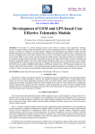
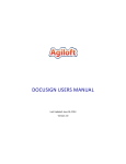
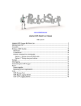
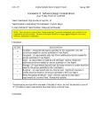
1
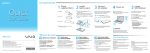
Water Quality Autonomous Robot Boat (W.A.R Boat) Irina Bouzina, Dennis Figueras, Joey Yuen Department of Electrical Engineering and Computer Science, University of Central Florida, Orlando, Florida, 32816-2450 custom solar panel was need for the boat to ensure that it would fit on the bow and not weigh it down. II. SYSTEM COMPONENT OVERVIEW To get a better understanding of the entire system an overview of each integral component that makes up the system will presented. This overview also explains how each component is connected and how they communicate with each other. A. Microcontroller Abstract — War Quality Autonomous Robot Boat (W.A.R Boat) is a self-sustaining semi-autonomous electrical and computer engineering project. W.A.R utilizes a mounted solar panel to recharge lithium ion batteries which power the entire system. A total of three batteries power the system, two for the printed circuit board and one for the motor. Autonomous motion is achieved through GPS guidance to a user selected waypoint. W.A.R is also outfitted with various water quality sensors and is capable of wirelessly transmitting data from the sensors to an on shore laptop. Index Terms — Autonomous, solar powered, wireless transmission, water quality, lithium ion battery. I. INTRODUCTION Inspiration for this project was drawn from a news article about a brain eating amoeba that targeted humans who swam in southern lakes and rivers. Though this project does not directly detect this brain eating amoeba, it does help by measuring various water quality measurements that can determine if a body is water is safe to enter. This project is implemented on a two-layer printed circuit board which houses the GPS module, XBee module, two microcontrollers, multiplexers, water quality circuits, and various other components. Once complete the project allows a user to send the boat to a specified latitude and longitude coordinate, where it is able to take five different water quality measurements and send them back wirelessly to an on-shore laptop. Once the user is done, they may send a command for the boat to return to its beginning location, or in a case where wireless connection was lost a timer will trigger the boat to return. To make this a self-sustaining system, small polycrystalline solar cells will be mounted together to form three separate modules which are placed together to form one panel which will charge the lithium ion batteries. This panel is mounted on front of the boat and protected from environmental factors with a clear piece of plexi-glass. A To collect all the water quality data and navigate the boat, a total of two Atmel ATmega328P microcontrollers are used. One microcontroller is responsible for reading water quality data and transmitting this data wirelessly, while the other microcontroller handles the GPS guided navigation of the boat. The ATmega328P microcontroller was chosen for its low power, high performance, and ample I/O pins. The 14 digital and 6 analog I/O pins allows communication between each water quality sensor and between the two microcontrollers using I2C.[1] To program each microcontroller, the Arduino UNO bootloader is loaded onto memory so the Arduino UNO board and IDE can be used for programming and debugging. B. Water Quality Circuits To convert the water quality sensor data into something readable for the microcontroller, the system will have five water quality circuits. These five water quality circuits are pH, temperature, Oxidation Reduction Potential (ORP), Dissolved Oxygen (D.O.), and Conductivity. The water quality circuits are manufactured by Atlas-Scientific, a company that specializes in creating water quality embedded products. The circuit has a relatively small footprint measuring less than one inch by one inch. Each circuit is operable at 3.3-5.5V, and communicates to the microcontroller using serial connectivity. Each circuit is low power consuming about 14mA at 5V and 4mA at 3.3V. Each circuit is outfitted with a variety of useful commands that allow the engineer to fully integrate them into the embedded system. Some of these commands allows the user to enable/disable debug LEDs to conserve power, change baud rates for integration with other devices, and calibration modes to ensure precise measurements of water. C. Water Quality Sensors Each water quality circuit is attached through a standard BNC connector. These water quality sensors are scientific grade monitoring devices, manufactured from AtlasScientific that can be submerged indefinitely. Each sensor has a fast response time of 95% in 1 second and accuracy within two decimal points. The sensors are light weight and vary in length from 67mm to 120mm. Before setup each sensor must be calibrated together with each water quality circuit using the calibration modes that are equipped with each circuit. To calibrate each the sensors, controlled solutions must be used, for example, 7.0 pH solution and regulated dissolved oxygen liquid. D. XBee RF Modules To transmit water quality data wirelessly, the system will use two XBee Pro RF Modules. These modules use the 802.15.4 stack which simplifies it for easy serial communication. Each XBee Pro runs on 3.3V at 215mA when transmitting data with a max transmission range of 1500m (1 mile) line-of-sight.[2] One XBee Pro is connected to the PCB which transmits the water quality data to our other XBee Pro which is connected to a laptop computer onshore. E. GPS Module The GPS chosen for the W.A.R boat is the EM-406A with the SirF start III high performance GPS chip set. It features high tracking sensitivity, a fast time to first fix at low signal level. It supports NMEA 0183 data protocol. It also has a built-in Supercap to reserve system data for rapid satellite acquisition, a built in patch antenna and an LED indicator to indicate fix or not. The EM-406A has 20 channels which are all in-view tracking and operates at 5V with a current draw of 44 mA. [3] E. Solar Cells Polycrystalline solar cells are used to provide the power for the system. There are three solar cell modules that are laid out in the front flat area of the boat. Each polycrystalline cell outputs an average voltage of 0.5 volts and current 0.3 amps. Ten cells are connected in series to produce one module. Each module generates approximately 1.5 watts of power; therefore the total power generated by all solar modules is 4.5 watts. F. Lithium Ion Charge Controller The system contains three uniform charge controllers that are each connected to a solar module and to a lithium ion battery. The charge controller is responsible of producing a stable current and voltage to the fragile chemistry lithium ion battery and to a load output. Both the load and battery connection have a voltage of 3.7 volts. The charge controller uses a MCP73871 chip that uses Voltage Proportional Charge Control to ensure low cost while still maintaining efficiency and stability of the managed power. Working with varying voltages due to the solar panel fluctuating light exposure, it is necessary to employ VPCC to produce a steady output voltage. The steady voltage output in VPCC is obtained by limiting the current, therefore increasing the voltage once the output voltage drops below a pre-set voltage value. [4] G. Lithium Ion Battery The batteries that are used for the system are the TENERGY Lithium Ion 18650 Cylindrical Flat Top Rechargeable 3.7 volt batteries. Each battery contains 3.7 volt 2600mAh high capacity. The maximum charge and discharge current is 1300mA and 2800mA, respectively. [5] Due to the fragile chemistry of the lithium ion batteries a built in printed circuit board controller is included with each battery to prevent explosive and harmful accidents. However, this controller is not reliable enough and is unable to handle varying voltages with efficiency; therefore it’s not enough to substitute the solar panel/lithium ion battery charge controller. III. SYSTEM CONCEPTS Shown in Fig. 1 is a block diagram of the overall system concepts. There are three major parts in the W.A.R boat system: the power system, the sensor communication system, and the navigation system. The power system is fully driven by solar energy that is derived by a polycrystalline solar cell panel. The sensor communication system uses XBees to communicate from/to the boat and utilizes the users’ commands which control the sensors. The navigation system works by having the user input the coordinates into the laptop which are then sent to the navigation microcontroller. After the boat travels to the selected location, the sensors acquire the necessary data and transmit it to the on shore XBee, soon after the boat returns to the home location. Each subsystem will be briefly described in this section. exception of the communication system which requires an input of 3.3 volts. To step down the voltage suitable for the communication system, a step down voltage regulator is used. More specifically the Micrel Electronics MIC5219. B. Sensor/Communication Sub-System Fig.1. Block components. diagram presenting major system A. Power Sub-System The entire system is powered by the solar panel. The solar panel contains three solar cell modules. Each module contains ten solar cells that are connected together in series. The output connection on each module is a DC barrel jack, which provides a secure connection to the charge controller. There are three charge controllers that are each connected to the lithium ion battery and to a load output. The first charge controller 3.7 volt load output is connected to the DC motor which draws a current of 0.7 amperes. Each solar cell module outputs a current of 0.2 amperes, the rest of the required current needed to run the motor for that time is supplemented by the battery. The second and third charge controllers have their outputs both connected in series. Since both of the charge controllers output 3.7 volts, connected in series they produce 7.4 volts to the output connection. Connected to the output of the two charge controllers is a PCB which contains the microcontrollers, sensors, and the communication system. All of the components on the PCB require a 5 volt input, with the exception of the communication system which requires an input of 3.3 volts. To adjust the voltage to 5 volts a step down voltage regulator is used. More specifically the STMicroelectronics LF50CV. From that point on all of the components requiring 5 volts are powered, with the To acquire water quality data, there are five water quality sensors in the system. Each sensor sends data when requested from the user/microcontroller. The user has a simple terminal menu to select which sensor data they would like to read. From this menu, a command is sent from the laptop XBee to the XBee on the water quality/navigation PCB. The sensor microcontroller then takes this command and configures the multiplexers to read data from the specified sensor. The sensor then polls water quality data for approximately 5-7 seconds. Each poll for water quality data is then sent back to the sensor microcontroller/XBee and transmitted back in real time to the laptop. Along with the ability to decide which water quality sensor to read from, the user can request the boat to return home. The command triggers the navigation microcontroller to turn on the motor and start calculating navigation back to its original latitude and longitude coordinate. C. Navigation Sub-system The navigation subsystem of this project is in charge of the motion of the W.A.R boat. This subsystem consists of an Atmel ATmega328P microcontroller, an EM-406A GPS device, a DC motor that spins the propeller, and a servo which turn the rudder. The navigation microcontroller performs all the distance and heading calculations needed to steer the boat. These calculations use data from the GPS device and are recalculated every quarter to ensure the boat is moving the right direction. The navigation microcontroller waits to receive a valid waypoint coordinate from the sensor microcontroller and for the GPS to have a lock before turning on the DC motor. The servo angle is set based on the heading calculation, the possible choices are: left, right or straight. Once W.A.R boat reaches the waypoint, the motor will turn off and the user is able to utilize the various on board sensors to measure water quality at that specific location. Once the user it done with the sensors, the user can order W.A.R to return to its starting position. If wireless communications is lost with W.A.R or after enough time has passed, W.A.R will automatically return home. IV. HARDWARE DETAILS To better understand the systems components, below will be technical explanations of major components. A. GPS NMEA 0183 Protocol The NMEA 0183 standard defines an electrical and data protocol for communications between marine instrumentation in this particular case, the GPS receiver. The NMEA output messages specifically developed and defined by SiRF for use within SiRF products are listed below in Figure 2. B. XBee Wireless Communication The XBee Wireless RF modules used in this project are embedded solutions allowing wireless connectivity between devices. These modules use the IEEE 802.15.4 networking protocol for peer-to-peer networking or multipoint networking. The XBee modules uses the same MAC (Medium Access Control) layers as the ZigBee protocol, but the XBee's have a proprietary upper layer by the manufacturer, Digi International. With this proprietary software, Digi International made a low cost and easy to configure wireless module. [1] To configure the two XBee modules for communication, the XBee that is connected to the laptop is then configured as the coordinator of the network which can send data to multiple XBee modules. The second XBee module which is attached to our main PCB will be configured as a receiver. C. Lithium Ion Charge Controller Fig.2. NMEA Output Messages [6] NMEA input messages enable the user to control the receiver while in the NMEA protocol mode. If the receiver is SiRF binary mode, all NMEA input message are ignored. Once the receiver is put into NMEA mode, the following message format may be used to command the module. 1. Message Identifier consisting of three numeric characters. Input messages being at MID 100. 2. Message specific data. 3. CKSUM is a two-hex checksum as defined in the NMEA specifications. 4. Each message is terminated using Carriage Return (CR) and Line Feed (LF). Fig.3. Transport message parameters. [6] There are three charge controllers that each input the output from the solar cells, after which the output of each charge controller is connected to a 3.7 volt lithium ion battery. The charge controller chip used to manage the voltage and current transitioning to the battery is the MCP73871 Stand Alone System Load Sharing and LiIon/Li-Polymer Battery Charge Management Controller. The chip employs a constant current, constant voltage algorithm with thermal regulation. Maximum current of 1.8 amperes of total input current control. The Microchip chip is used with the intention to make the charging system efficient, while still maintaining low cost and time effectiveness. The efficiency of the charging is ensured by employing Voltage Proportional Charge Control (VPCC), which reduces the charging current as it increases the voltage as soon as the input voltage (output solar panel voltage) drops below the preset battery charge voltage. The VPCC feature is activated on the chip once the voltage reaches above 1.23 volts and is disabled if it is connected to the pin IN. The pre-set battery charge voltage is referenced in the voltage divider resistor value design. By selecting certain resistor values the system has a specific charging voltage. The voltage divider equation is displayed below. [4] The charge controller provides a charge current of up to 500mA to the lithium ion battery which is an acceptable value and is lower than the standard charging current for the TENERGY 18650 lithium ion battery. D. Water Quality Measurements/Circuits To understand the importance of the water quality measurements the system can take, a general overview of each parameter is given. The charge controller contains three two-pin headers and one DC barrel power jack. The first female header takes the solar cell module output as its input. It also shares the same connection with the barrel power jack. The two different connection types are there for functionality purposes, because the female headers contain an easy connect/disconnect for the wires. The barrel power jack connection provides a secure connection and is used in the final production of the project. The charge controller contains three different status LEDs that notify the user of the charge status of the lithium ion battery. The first LED is labeled “PWR” and indicates if the charge controller has a good power connection. If the LED is not turned ON then something is wrong with the solar cell power supply. The second LED is labeled “CHRG” and it indicated the current charging status of the battery. If the LED is lit then the battery not yet full and is still consuming charge. Another option indication for this LED is if the voltage of this battery is low, below 3.1 volts. Therefore if the voltage of the lithium ion battery drops below 3.1 volts this LED turns ON. The third LED labeled “DONE” indicates that the battery has reached full charge of 3.7 volts. The charge controller allows simultaneous use and charging of the battery called load sharing. Therefore the charge controller parts and battery itself aren’t strained due to constant charge and discharge as the system is being charged and consuming power. On the charge controller there are two separate output connections labeled “BATT” and “LOAD”, one of which is connected to the lithium ion battery and the other is connected to a component receiving the controlled power, respectively. To enable load sharing included in the charge controller chip design is a pass transistor that is connected to the output load from the input voltage. When the charge controller is connected to the solar panel, the lithium ion battery, and a load, the load current is being drawn directly from the solar panel connection. If the load current is lower than the required current, the battery will supplement the additional needed current by up to 1.8 amperes. pH: pH is a measure of the acidity or basicity of an aqueous solution. Measuring the pH of a body is very important because it can determine if there are pollutants or high levels of acid rain in the water. As seen in Figure 4, if a body of water drops to a pH level of 5 or less, this will begin to kill off aquatic life. The death of aquatic life can be detrimental to anyone in the body of water because the rotting tissue can release toxins and bacteria. Fig.4. pH chart showing levels at which aquatic life can survive. [7] Temperature: The temperature of a lake is vital to its ecosystem because it can reduce oxygen levels for aquatic life. As the temperature of a body of water increased the oxygen levels will begin to decrease. As the oxygen depletes fish and aquatic plants will begin to die-off. Again this die-off can cause toxins and bacteria to enter the water. Temperature of the water is one of the main factors that cause fish die-off in many bodies of water. Dissolved Oxygen: Dissolved Oxygen measured the amount of gaseous oxygen in a solution. The oxygen may enter a body of water from the air, aeration of the water (movement) and waste from aquatic plants through photosynthesis. As described in the Temperature section, as the temperature rises, oxygen levels start to fall. As seen in Figure 5, temperature and dissolved oxygen have a direct effect on each other. V. SOFTWARE DETAILS The software for this project is coded in the C language using the Arduino IDE. An Arduino Uno board is used to program and prototype the two microcontrollers (Atmel ATmega328P). Four libraries are used in the creation of the navigation code. These are SoftwareSerial.h, TinyGPS.h, SoftwareServo.h and Wire.h. The SoftwareSerial library allows for serial communication on any of the Uno’s digital pin, this is primarily used for reading incoming GPS data, water quality data, and for debugging. The TinyGPS provides most the NMEA GPS functionality (position, date, time, altitude, speed and course), while keeping resource consumption low by avoiding any mandatory floating point dependency and utilizing only key GPS fields. The SoftwareServo library can drive servos on all pins simultaneously. This library does not stop interrupts so millis() can still be used and incoming serial data will not be lost. The Wire library allows communication with I2C between the two microcontrollers. A. Navigation Software Fig.5. Oxygen Concentration vs. Temperature [8] Conductivity: The conductivity of water measures its ability to carry an electrical current. Measuring conductivity can show the total dissolved solids (TDS) of the water. The TDS of water can show us aesthetic qualities of drinking water and can also be an indicator if there are chemical contaminants. These chemical contaminants may reach a body of water from pollution or run off from rivers that carry polluted soil/water. Oxidation Reduction Potential (ORP): ORP measures the ability for a body of water to break down waste, such as dead fish and aquatic plants. ORP is an important measurement in water quality because it can determine how well bacteria are decomposing dead tissue in the water. To achieve autonomous navigation, the W.A.R boat is outfitted with several components. These are a brushed DC motor which is connected to the propeller via a brass shaft, a standard size servo, which moves the rudder and a GPS device, specifically the EM-406A. The DC motor is rated at 3-24V with a current draw of 0.5A when loaded with the propeller. The servo provides 45 oz.-in of torque at a speed of 60 degrees per 0.17 seconds. A thin eight inch long brass wire connects the control arm of the servo to the control arm of the rudder. The GPS has a twenty two channel receiver and is accurate within 10 meters. A summary flow chart of the software procedures can be seen below in Figure 6 below. As shown in the following flowchart, there are two requirements must be met before the boat is able to move. The first requirement is that the GPS must have valid data and save its current location as the return home location. From a cold start this will normally take less than one minute, depending on weather or outside interference. From a hot start, this will take less than a few seconds. The second requirement is that the user has sent the boat a valid waypoint to travel to. The user is able to input a GPS coordinate in the form of two floats into the serial terminal (i.e. 28.600402, -81.169385). These two values are wirelessly transmitted to the sensor microcontroller via an XBee receiver and transmitter, and then transmits latitude/longitude data to the navigation microcontroller via I2C communications. from the GPS device. Once both the needed heading (found in (4)) and the current heading (from GPS device) are known, then they can be compared by simple subtraction. Depending on the result of the subtraction, the direction that the rudder must be turned can be found. The GPS is polled for new data every quarter second which trigger the start of new distance and bearing calculations. B. Navigation Equations Fig.6. Summary of navigation software procedure. There are also two values that must be calculated in order to achieve autonomous motion. These are distance and bearing between the start and end points. The data from the GPS can be used to calculate both of these values. The distance can be calculated using the Haversine Formula shown below in the navigation equations section of this paper. The Haversine Formula is a great circle formula that calculates the shortest distance between two points on a sphere. It can be split into three separate parts. Shown in (1), latitude ( ) and longitude ( ) coordinates are converted to radians and used to calculate the value a. The atan2 function shown in (2) uses two arguments instead of one in order to gather information on the signs of input and return the appropriate quadrant of the computed angle. The final value shown in (3) is calculated by multiplying by the radius of the Earth (R = 6,371 km) with the value c found in (2). [9] The bearing between two points can be calculated using (4). This equation returns a value between -180 and 180 degrees. If the returned value is negative, it must be made positive by adding 360 degrees. As long as the boat is moving, the current direction of travel can be obtained The first three equations are parts of the Haversine Formula used to calculate the shortest distance between two points on a sphere where is latitude converted to radians, is longitude converted to radians, and R is the radius of the Earth, mean of 6,371 km. The fourth equation is used bearing from the start point to the end point. [9] VI. BOARD DESIGN A. Water quality/Navigation PCB The water quality data and navigation system are implemented onto a two-layer printed circuit board. Along with the water quality circuits and navigation components, the PCB also contains the voltage regulator, XBee module, a relay, and two multiplexers. For simplicity, all parts on the PCB will be mounted using through-hole components. B. Charge Controller PCB To keep the batteries charge, the system will have three charge controller printed circuit boards. Each circuit is responsible for charging one lithium ion battery. The PCB has all surface mount parts mainly because the MCP73871 charge controller only comes in a surface mount package. On the PCB there are also three 2-pin headers for an optional DC power input, connections to the battery, and connections to a load. ACKNOWLEDGEMENT The authors wish to acknowledge Dr. Samuel Richie for his advisement with this project. The authors would also like to thank Duke Energy for the sponsorship of this project. REFERENCES [1] Atmel Corporation. (2009) Atmega328P Datasheet. Retrieved 28 March 2014, World Wide Web: http://www.atmel.com/Images/doc8161.pdf [2] Digi International Incorporated. (2008) XBee/XBeePRO Datasheet. Retrieved 28 March 2014, World Wide Web: http://ftp1.digi.com/support/documentation/9000098 2_A.pdf [3] Global Sat. (2006) Product User manual GPS receiver Engine Board . Retrieved 27 March 2014, World Wide Web: https://www.sparkfun.com/datasheets/GPS/EM406A_User_Manual.PDF [4] Microchip. (2013) MCP73871 Datasheet. Retrieved 25 March 2014, World Wide Web: (http://ww1.microchip.com/downloads/en/DeviceDoc /20002090C.pdf [5] Tenergy. (2013) Tenergy Li-Ion 18650. Retrieved 30 March 2014, World Wide Web: http://www.tenergy.com/30005 [6] SiRF Technology Incorporated. (2006) NMEA Reference Manual. Retrieved 26 March 2014, World Wide Web: https://www.sparkfun.com/datasheets/GPS/NMEA% 20Reference%20Manual1.pdf [7] Environmental Protection Agency. pH Scale. Retrieved 25 March 2014, World Wide Web: http://www.epa.gov/acidrain/education/site_students/ phscale.html [8] The Engineering ToolBox. Oxygen Solubility in Fresh and Sea Water. Retrieved 29 March 2014, World Wide Web: http://www.engineeringtoolbox.com/oxygensolubility-water-d_841.html [9] Movable Type Scripts. Calculate distance, bearing, and more between latitude/longitude points. Retrieved 29 March 2014, World Wide Web: http://www.movable-type.co.uk/scripts/latlong.html\ THE ENGINEERS Irina Bouzina is a senior studying Electrical Engineering at the University of Central Florida. As the Industry Chair of the IEEE UCF branch she has organized several information sessions and interactive workshops with leading engineering companies. Her current and previous Electrical Engineering experience includes working with power system design from an internship and senior design project. Also, she has had a strong academic focus on communication systems with taking: Analog and Digital Communications, Digital Communications, and Communication Systems. During free time she enjoys nature hiking, painting, and relaxing at the beach. Dennis Figueras is a senior at the University of Central Florida, graduating in May 2014 with a Bachelor’s degree in Computer Engineering. He plans on pursuing a career in software development preferably in robotics, AI, or security. His prior experiences include, developing on the Android OS, Arduino, and the Texas Instruments MSP430. His hobbies include watching movies, small scale programming projects, and assembling computers. Joey Yuen is a senior at the University of Central Florida, graduating in May 2014 with a Bachelor’s degree in Computer Engineering. He will be joining Texas Instruments as a Field Applications Engineer in Dallas, Texas upon graduation. His interests include embedded systems, low-level software development, and computer architecture. His hobbies include working on Arduino projects, reading technology news, and basketball.