1
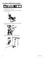
Operation
Fiberglass Choppers
GC-1021B
Fiberglass Roving Choppers
For use with Polyester Resin, and Gel-Coat
Maximum air pressure:
100 psi. (0.7 MPa, 7 bar)
Important Safety Instructions
Read all warnings and instructions in
this manual. Save these instructions.
II 2 G
Contents
Warnings .......................................................... 3
Important Safety Information ......................... 5
Grounding ........................................................ 6
Set-Up ............................................................... 7
Pressure Relief Procedure ........................... 12
Start-Up .......................................................... 13
Parts ............................................................... 15
Assembly Drawings....................................... 16
Sub-Assembly Drawings .............................. 20
Maintenance................................................... 22
Accessories ................................................... 26
Technical Data ............................................... 27
Graco Ohio Standard Warranty .................... 28
Graco Ohio Information ................................ 28
2
GC-1021B
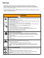
Warnings
The following warnings are for the setup, use, grounding, maintenance, and repair of this equipment.
The exclamation point symbol alerts you to a general warning and the hazard symbol refers to procedureVSHFL¿FULVN5HIHUEDFNWRWKHVHZDUQLQJV$GGLWLRQDOSURGXFWVSHFL¿FZDUQLQJVPD\EHIRXQGWKURXJKRXWWKH
body of this manual where applicable.
• See Important Safety Information - MEKP, Polyester Resins and Gel-Coats and Spraying and Lamination
Operations section of this manual.
9#40+0)
FIRE AND EXPLOSION HAZARD
Flammable fumes, such as solvent and paint fumes, in work area can ignite or explode. To help
SUHYHQW¿UHDQGH[SORVLRQ
• Use equipment only in well ventilated area.
• Eliminate all ignition sources; such as pilot lights, cigarettes, portable electric lamps, and plastic
drop cloths (potential static arc).
.HHSZRUNDUHDIUHHRIGHEULVLQFOXGLQJVROYHQWUDJVDQGJDVROLQH
'RQRWSOXJRUXQSOXJSRZHUFRUGVRUWXUQSRZHURUOLJKWVZLWFKHVRQRURIIZKHQÀDPPDEOH
fumes are present.
*URXQGDOOHTXLSPHQWLQWKHZRUNDUHD6HHGrounding instructions.
• Use only grounded hoses.
+ROGJXQ¿UPO\WRVLGHRIJURXQGHGSDLOZKHQWULJJHULQJLQWRSDLO
,IWKHUHLVVWDWLFVSDUNLQJRU\RXIHHODVKRFNstop operation immediately. Do not use
equipment until you identify and correct the problem.
.HHSDZRUNLQJ¿UHH[WLQJXLVKHULQWKHZRUNDUHD
PERSONAL PROTECTIVE EQUIPMENT
You must wear appropriate protective equipment when operating, servicing, or when in the
operating area of the equipment to help protect you from serious injury, including eye injury,
LQKDODWLRQRIWR[LFIXPHVEXUQVDQGKHDULQJORVV7KLVHTXLSPHQWLQFOXGHVEXWLVQRWOLPLWHGWR
• Protective eyewear
&ORWKLQJDQGUHVSLUDWRUDVUHFRPPHQGHGE\WKHÀXLGDQGVROYHQWPDQXIDFWXUHU
• Gloves
• Hearing protection
MOVING PARTS HAZARD
0RYLQJSDUWVFDQSLQFKRUDPSXWDWH¿QJHUVDQGRWKHUERG\SDUWV
• Keep clear of moving parts.
• Do not operate equipment with protective guards or covers removed.
3UHVVXUL]HGHTXLSPHQWFDQVWDUWZLWKRXWZDUQLQJ%HIRUHFKHFNLQJPRYLQJRUVHUYLFLQJ
equipment, follow the Pressure Relief Procedure in this manual. Disconnect power or air
supply.
TOXIC FLUID OR FUMES HAZARD
7R[LFÀXLGVRUIXPHVFDQFDXVHVHULRXVLQMXU\RUGHDWKLIVSODVKHGLQWKHH\HVRURQVNLQLQKDOHGRU
swallowed.
5HDG06'6¶VWRNQRZWKHVSHFL¿FKD]DUGVRIWKHÀXLGV\RXDUHXVLQJ
6WRUHKD]DUGRXVÀXLGLQDSSURYHGFRQWDLQHUVDQGGLVSRVHRILWDFFRUGLQJWRDSSOLFDEOH
guidelines.
$OZD\VZHDULPSHUYLRXVJORYHVZKHQVSUD\LQJRUFOHDQLQJHTXLSPHQW
GC-1021B
3
Warnings
9#40+0)
SKIN INJECTION HAZARD
+LJKSUHVVXUHÀXLGIURPJXQKRVHOHDNVRUUXSWXUHGFRPSRQHQWVZLOOSLHUFHVNLQ7KLVPD\ORRN
OLNHMXVWDFXWEXWLWLVDVHULRXVLQMXU\WKDWFDQUHVXOWLQDPSXWDWLRQGet immediate surgical
treatment.
• Do not point gun at anyone or at any part of the body.
• Do not put your hand over the dispense outlet.
'RQRWVWRSRUGHÀHFWOHDNVZLWK\RXUKDQGERG\JORYHRUUDJ
(QJDJHWULJJHUORFNZKHQQRWVSUD\LQJ
• Follow Pressure Relief Procedure in this manual, when you stop spraying and before cleaning,
FKHFNLQJRUVHUYLFLQJHTXLSPHQW
EQUIPMENT MISUSE HAZARD
Misuse can cause death or serious injury.
'RQRWRSHUDWHWKHXQLWZKHQIDWLJXHGRUXQGHUWKHLQÀXHQFHRIGUXJVRUDOFRKRO
'RQRWH[FHHGWKHPD[LPXPZRUNLQJSUHVVXUHRUWHPSHUDWXUHUDWLQJRIWKHORZHVWUDWHGV\VWHP
component. See Technical Data in all equipment manuals.
8VHÀXLGVDQGVROYHQWVWKDWDUHFRPSDWLEOHZLWKHTXLSPHQWZHWWHGSDUWV6HHTechnical Data
LQDOOHTXLSPHQWPDQXDOV5HDGÀXLGDQGVROYHQWPDQXIDFWXUHU¶VZDUQLQJV)RUFRPSOHWH
information about your material, request MSDS forms from distributor or retailer.
&KHFNHTXLSPHQWGDLO\5HSDLURUUHSODFHZRUQRUGDPDJHGSDUWVLPPHGLDWHO\ZLWKJHQXLQH
manufacturer’s replacement parts only.
• Do not alter or modify equipment.
• Use equipment only for its intended purpose. Call your distributor for information.
5RXWHKRVHVDQGFDEOHVDZD\IURPWUDI¿FDUHDVVKDUSHGJHVPRYLQJSDUWVDQGKRWVXUIDFHV
'RQRWNLQNRURYHUEHQGKRVHVRUXVHKRVHVWRSXOOHTXLSPHQW
.HHSFKLOGUHQDQGDQLPDOVDZD\IURPZRUNDUHD
• Comply with all applicable safety regulations.
4
GC-1021B
Important Safety Information
Methyl Ethyl Ketone Peroxide (MEKP)
MEKP is among the more hazardous materials
found in commercial channels. Proper handling
of the “unstable (reactive)” chemicals presents a
GH¿QLWHFKDOOHQJHWRWKHSODVWLFVLQGXVWU\7KH
KLJKO\UHDFWLYHSURSHUW\ZKLFKPDNHV0(.3
valuable to the plastics industry in producing the
curing reaction of polyester resins and gel-coats
also produces the hazards which require great care
and caution in its storage, transportation, handling,
processing and disposal.
:RUNHUVPXVWEHWKRURXJKO\LQIRUPHGRIWKHKD]DUGV
that may result from improper handling of MEKP,
especially in regards to contamination and heat.
They must be thoroughly instructed regarding the
SURSHUDFWLRQWREHWDNHQLQWKHVWRUDJHXVHDQG
disposal of MEKP and other hazardous materials
used in the laminating operation.
0(.3LVÀDPPDEOHDQGSRWHQWLDOO\H[SORVLYH
as well as potentially damaging to the eyes and
skin.
Read material manufacturer’s warnings and
PDWHULDO06'6WRNQRZVSHFL¿FKD]DUGVDQG
precautions related to MEKP.
Contaminated MEKP can become explosive.
Prevent contamination of MEKP with other materials, which includes, but is not limited to polyester
overspray, polymerization accelerators and promoters, and non-stainless metals. Even small amounts
RIFRQWDPLQDWHVFDQPDNH0(.3H[SORVLYH7KLVUHaction may start slowly, and gradually build-up heat,
ZKLFKFDQDFFHOHUDWHXQWLO¿UHRUDQH[SORVLRQUHVXOW
7KLVSURFHVVFDQWDNHIURPVHFRQGVWRGD\V
Heat applied to MEKP, or heat build-up from contamination reactions can cause it to reach what is
FDOOHGLWV6HOI$FFHOHUDWLQJ'HFRPSLVLWLRQ7HPSHUDWXUH6$'7ZKLFKFDQFDXVH¿UHRUH[SORVLRQ
Spills should be promptly removed, so no residues
remain. Spillage can heat up to the point of selfignition. Dispose in accordance with manufacture’s
recommendation.
Store MEKP in a cool, dry and well-ventilated area
in the original containers away from direct sunlight
and away from other chemicals. It is strongly recommended that the storage temperature remain below
86° F (30° C). Heat will increase the potential for exSORVLYHGHFRPSRVLWLRQ5HIHUWR1)3$
.HHS0(.3DZD\IURPKHDWVSDUNVDQGRSHQ
ÀDPHV
GC-1021B
Current catalysts are premixed and do not require
any diluents. GlasCraft strongly recommends that diluents not be used. Diluants add to the possibility of contaminates entering the catalyst system. Never dilute
MEKP with acetone or any solvent since this can proGXFH DQ H[WUHPHO\ VKRFNVHQVLWLYH FRPSRXQG ZKLFK
can explode.
Use only original equipment or equivalent parts
IURP *ODV&UDIW LQ WKH FDWDO\VW V\VWHP LH KRVHV ¿Wtings, etc.) because a hazardous chemical reaction
may result between substituted parts and MEKP.
To prevent contact with MEKP, appropriate personal
protective equipment, including chemically impermeable gloves, boots, aprons and goggles are required
IRUHYHU\RQHLQWKHZRUNDUHD
Polyester Resins and Gel-Coats
Spraying materials containing polyester resin and
gel-coats creates potentially harmful mist, vapors and
atomized particulates. Prevent inhalation by providing
VXI¿FLHQWYHQWLODWLRQDQGWKHXVHRIUHVSLUDWRUVLQWKH
ZRUNDUHD
Read the material manufacturer’s warnings and maWHULDO06'6WRNQRZVSHFL¿FKD]DUGVDQGSUHFDXWLRQV
related to polyester resins and gel-coats.
To prevent contact with polyester resins and gelcoats, appropriate personal protective equipment,
including chemically impermeable gloves, boots,
aprons and goggles are required for everyone in the
ZRUNDUHD
Spraying and Lamination Operations
Remove all accumulations of overspray, FRP sandings, etc. from the building as they occur. If this waste
LVDOORZHGWREXLOGXSVSLOODJHRIFDWDO\VWLVPRUHOLNHO\
WRVWDUWD¿UH
If cleaning solvents are required, read material
PDQXIDFWXUH¶VZDUQLQJVDQGPDWHULDO06'6WRNQRZ
VSHFL¿FKD]DUGVDQGSUHFDXWLRQV*ODV&UDIWUHFRPPHQGVWKDWFOHDQXSVROYHQWVEHQRQÀDPPDEOH
GlasCraftUHFRPPHQGVWKDW\RXFRQVXOW26+$
6HFWLRQVDQG1)3$
1R&KDSWHUDQG1)3$1RIRUIXUWKHU
guidance.
5
Grounding
This equipment needs to be grounded.
Ground the dispense gun through connection to a
*ODV&UDIWDSSURYHGJURXQGHGÀXLGVXSSO\KRVH
&KHFN\RXUORFDOHOHFWULFDOFRGHDQGUHODWHGPDQXDOV
for detailed grounding instructions of all equipment in
WKHZRUNDUHD
A grounding wire and clamp are provided,
assembly p/n 17440-00 with all FRP equipment.
6
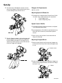
GC-1021B
Set-Up
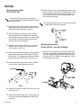
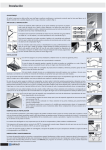
Mounting Instructions
B-410, LPA 2 Gun
8. $GMXVW&KRSSHUPRXQWXQWLOFKRSSHGJODVVHQWHUVVSUD\
pattern at desired entry location. Chopped glass should
be uniformly entering the spray pattern resulting in an
evenly distributed resin spray and chopped glass pattern on the test substrate.
The following Mounting Instructions pertain to
mounting a Model B-410 onto a Model LPA, Model
LPA-II Spray Gun.
1. Remove Set Screw, P/N D-145-08C from the Gun
Test spraying should be done on a clean piece of paper
or cardboard and disposed of properly.
body located where the Chopper is mounted and replace at the top of the handle. (see Fig. 1)
2. $WWDFKWKH&KRSSHUDVVHPEO\LQWRWKHPRXQWLQJ
hold and tighten with the Chopper snout pointing
down into the resin spray pattern. The correct adjustments for glass entering the pattern will be done
when the spray test is completed.
3. Chopper “On/Off” Lever, P/N B-310-11, located on
the base of the Chopper mount, should be in the
“OFF” position. (see Fig. 2)
4. Thread roving from box through the Roving Guidance
V\VWHPDQGLQWRWKHEDFNRIWKH&KRSSHU)HHG%DU
P/N B-210-15. It is suggested that the top feed hole
be used if only one strand of glass is being used.
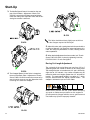
Mounting Instructions
B-410, & B-510, Indy Gun 23550-00
1. 7KH%&KRSSHU$VV\0RXQWVWR&XWWHU3LYRW
Tube, P/N 21491-00 on Chopper Rotating Mount, P/N
23513-00. Tighten down Bar, P/N B-310-4 with Screws,
31)31;;+RVHDWWDFKHVWR¿WWLQJ
31LQEDFNRIJXQ
5. $IWHUDOOFRPSRQHQWVKDYHEHHQVHFXUHO\LQVWDOOHG
turn on main air supply slowly until fully on.
D-145-08C
Fig. 1
6. $FWLYDWHWKH&KRSSHU³2Q2II´/HYHUWRWKH³2Q´SRVL
tion. (see Fig. 2)
7. Depressing the Gun Trigger fully, a spray pattern of
resin and catalyst with chopped glass should now
be present.
GC-1021B
7
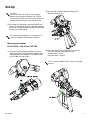
Set-Up
2. The Slide Valve, P/N 20086-01 controls air to the
Gun for the Chopper. Sliding it forward turns the air
RQZKLOHVOLGLQJLWEDFNWXUQVWKHDLURII
Chopper Air Requirements
100 PSI / 8 CFM
Adjusting Speed & Blower Air
1.7KH%ORZHU$LULVDGMXVWHGE\WKH7KXPE6FUHZ31%
$2QO\DVPDOODPRXQWRIDLULVUHTXLUHGWR
a.
Cool Chopper Head.
E
$VVLVWLQ'LVSHUVLQJFKRS
6SHHG&RQWURO0XIÀHU
1.7KH0XIÀHU$VVHPEO\FRQWUROVWKH$PRXQWDQG6SHHG
RIDLUH[KDXVWLQJWKH$LU0RWRU
2.$VWKH6SHHG.QRE31DQG0DFKLQH6FUHZ
31)LVWXUQHGRXWWKH$LU0RWRUVSHHGLQ
creases.
3.2QFHLWLVVHW/RFNWKH.QRE6FUHZGRZQZLWKWKH
Body, P/N 21561-00.
3. 7KH*XQ7ULJJHULVVWDJHGóSXOORQWKHWULJJHUZLOO
DFWXDWHPDWHULDORQO\)XOOEDFNRQWKHWULJJHUDFWX
tes the Chopper and Material. The Stager can be
adjusted by adjusting the Set screw, P/N 23532-01
in the Gun Trigger, p/n 23503-00.
Adjusting Chopper Mount
1. Loosen Screw, P/N 8212-16F to twist the Chopper side
to side on the Pivot Tube, P/N 21491-00. Retighten once
it is set.
Loosen screws
2. Loosen Screw, P/N 20188-16C to pivot the Chopper up
GRZQRQWKH&KRSSHU%UDFNHW315HWLJK
ten once it is set.
Loosen
8
GC-1021B
Set-Up
For B-510
Loosen Lock Nut, P/N 7729-04, Pivot Chopper
Mount to desired angle, Retighten P/N 7729-04.
2QFHJHQHUDOSRVLWLRQFDQEHIRXQG¿QHWXQLQJFDQ
be adjusted by moving the chute, P/N B-510-22.
2.$LU+RVH31;;DWWDFKHVWR¿WWLQJ31
RQEDFNRIJXQ
3. The Snout, P/N 23543-00 is standard with the Indy
System. The end of the Snout is adjustable. Optional
snouts are available for the B-410 only, which include
the B-210-91 and B-210-92.
Test spraying should be done on a clean piece of
paper or cardboard and disposed of properly.
Mounting Instructions
B-410, B-510, Indy-X Gun 23575-00
1. 7KH%%&KRSSHU$VVHPEO\PRXQWVWR
Cutter Pivot Tube, P/N 21491-00 on Chopper Valve,
P/N 23569-00. Once Chopper is set, tighten Cutter
Clip, P/N B-310-4 with Screws.
3. The Cutter Valve Lever, P/N B-310-11 controls air
ÀRZWRWKHFKRSSHU3HUSHQGLFXODUWRWKH
&KRSSHU9DOYH $LU2Q
,QOLQHZLWK9DOYH $LU2))
This is a positive ON/OFF valve. It does not regulate
Air Flow.
GC-1021B
9
Set-Up
4. 7KH&DWDO\VW$WRPL]LQJ$LU/LQHFRQQHFWVWR&RQQHF
tor Fitting, P/N 20796-00. When the gun is triggered,
/LQH$LUZLOOUXQWKH&KRSSHU0RWRUDQGUHJXODWHGDLU
ZLOOÀRZWKUXWRWKHDWRPL]HGFLUFXLW
For B-510
A general position can be found. Fine tuning of the
Glass angle can be adjusted by moving the Chute
P/N, B-510-22.
Centering Adjust
Loosen Bar Screws, P/N 8212-16F and Twist Chopper
left or right to desired location, then retighten P/N 821216F Shoulder Screw.
Bar
Chopper Air Requirements
100 PSI @ 8 CFM
Adjusting Speed & Blower Air
1. The blower air is adjusted by the Thumb Screw, P/N
%$DVPDOODPRXQWRIDLULVUHTXLUHGWR
a. Cool Chopper Head
E$VVLVWLQ'LVSHUVLQJFKRS
Mounting Instructions
B-410, B-510, Formula Gun 23750-00
1. 7KH%%&KRSSHU$VVHPEO\PRXQWVWR
Cutter Pivot Tube, P/N 21491-00. Once the Chopper
is set, tighten Cutter Clip, P/N B-310-4 with Screws.
Adjusting Chopper Mount
Angle Adjust:
1. /RRVHQ/RFN1XW313LYRW&KRSSHU
0RXQWWRGHVLUHG$QJOH5HWLJKWHQ31+H[
Nut.
/RFN1XW
10
GC-1021B
Set-Up
2.$LU+RVH31;;DWWDFKHVWR¿WWLQJ31
RQEDFNRIJXQ
Chopper Air Requirements
100 PSI / 8 CFM
Adjusting Speed & Blower Air
1.7KH%ORZHU$LULVDGMXVWHGE\WKH7KXPE6FUHZ31%
$2QO\DVPDOODPRXQWRIDLULVUHTXLUHGWR
a.
Cool Chopper Head.
E
$VVLVWLQ'LVSHUVLQJFKRS
6SHHG&RQWURO0XIÀHU
1.7KH0XIÀHU$VVHPEO\FRQWUROVWKH$PRXQWDQG6SHHG
RIDLUH[KDXVWLQJWKH$LU0RWRU
2.$VWKH6SHHG.QRE31DQG0DFKLQH6FUHZ
31)LVWXUQHGRXWWKH$LU0RWRUVSHHGLQ
creases.
3.2QFHLWLVVHW/RFNWKH.QRE6FUHZGRZQZLWKWKH
Body, P/N 21561-00.
Adjusting Chopper Mount
3. The Cutter Valve, P/N 23776-00 controls the air
ÀRZWRWKHFKRSSHU
1. Loosen Screw, P/N 8212-16F to twist the Chopper side
to side on the Pivot Tube, P/N 21491-00. Retighten once
it is set.
This is a positive ON/OFF valve. It does not regulate
Air Flow.
2. Loosen Screw, P/N 7958-16C to pivot the Chopper up
GRZQRQWKH&KRSSHU%UDFNHW315HWLJK
ten once it is set.
GC-1021B
11
Pressure Relief Procedure
7RUHOLHYHÀXLGDQGDLUSUHVVXUHV
1. Push down Yellow slide valve, P/N 21402-00 to bleed
off air to system.
2. Open P/N 21228-00 on catalyst pump to recirculation
position.
3. Open P/N 21192-00 on bottom of material pump.
12
GC-1021B
Start-Up
Notice
Air Requirements
$OO*ODV&UDIW&KRSSHUVUHTXLUH&)0FXELFIHHWSHU
PLQXWH#36,RIGU\¿OWHUHGFRPSUHVVHGDLU7KH
air supply hose to the Chopper must be new and have
at least a 5/16” inside diameter.
Notice
Do not attempt to use lower air pressures or a smaller
hose as erratic operation may result.
Do not wet the roving or attempt to feed
frayed roving into the Chopper as this may cause it to
wrap around the feed roller and jam.
2. 7KH0RWRU2LOHULVORFDWHGRQWKHIRUZDUGSRUWRIWKH$LU
Motor. It is recommended that the Oiler Felt, P/N 378,
EHOXEULFDWHGZLWK$LU0RWRU2LO31'HSHQGLQJRQ
use, it is generally recommended that two or three drops
of oil be placed on the Felt every other day.
Chopper Operation
Models B-410 / B-510
1. To introduce roving to the Chopper, cut the free end
of the roving cleanly and double it over approximately one inch from the end. Feed into one of the
WKUHHKROHVSURYLGHGLQWKHEDFNRIWKHFXWWHUZKLOH
running at moderate speed.
B-410
B-410
B-510
GC-1021B
B-510
13
Start-Up
3. 7KH0XIÀHU6SHHG&RQWUROLVORFDWHGRQWKHUHDU
SRUWRIWKH$LU0RWRU$GMXVWPHQWRI.QRE31
FRQWUROVWKH$LU0RWRUVSHHGDQGGHWHU
PLQHVWKHFXWWLQJUDWH$GMXVWWKLVYDOYHXQWLOWKHGH
sired glass content is achieved.
B-510
B-410
This Valve should be at least slightly open at all times
RUWKH&KRSSHUPD\WHQGWR¿OODQGMDP
5. $GMXVWWKLVYDOYHXQWLODJRRGJODVVUHVLQIDQUHVXOWVZLWKD
minimum of drop-off. If an excessive amount of bypass air is
XVHGWKHURYLQJPD\¿ODPHQWL]HRUFRWWRQFDXVLQJYDULRXV
wet-out problems.
6.:KHQGHVLUHGDGMXVWPHQWKDVEHHQPDGHORFN7KXPE
6FUHZ31%$LQSODFHE\WLJKWHQLQJ/RFN1XW
31%$'RQRWRYHUWLJKWHQ
5RYLQJ&XW/HQJWK$GMXVWPHQW
B-510
4. The Chopper Blower Control Valve is located on
WKHUHDURIWKH%DFN3ODWH$GMXVWPHQWRI7KXPE
6FUHZ31%$FRQWUROVWKHDPRXQWRIE\
pass air which serves to vary the dispersion of the
cut roving as it leaves the Chopper.
7KHFXWOHQJWKRIWKHURYLQJ¿EHUVPD\YDU\IURP´WR´
depending upon the number of blades in the cutting head.
The cutting head has a circumference of 4” and is divided by
HLJKWVORWVDW´LQWHUYDOV$Q\QXPEHURIEODGHVPD\EH
omitted to achieve cut-lengths greater than 1/2” or blends of
lengths. The most popular length in use today is 1”, which
may be achieved with four equally spaced blades. The
chopper is delivered to you set in this matter.
Mask FilterEar
Relieve all air pressure from the system before attempting
any repair or maintenance procedures on this equipment.
Do not operate the Chopper with the cover or guard removed.
7KHEODGHVPD\À\IUHHLILPSURSHUO\LQVWDOOHG
B-410
14
GC-1021B
Parts
)LEHUJODVV5RYLQJ&KRSSHUV%%
Standard Equipment
Part
Number
Description
B-410
Fiberglass Chopper
GC-1021
86(50$18$/
Standard Equipment
Part
Number
Description
B-510
Fiberglass Chopper
GC-1021
86(50$18$/
GC-1021B
15
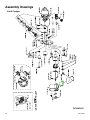
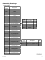
Assembly Drawings
B-410 Chopper
REVISION R
16
GC-1021B
Assembly Drawings
B-410 Chopper
Part
Number
Description
378
FELT OILER
13076-10
O-RING
13076-11
O-RING
17390-02
635,1*:$6+(5
5133-62MD
61$35,1*
7606-05
O-RING
7733-13
NUT
7734-06
/2&.:$6+(5
7958-48C
0$&+,1(6&5(:
8160-12C
SET SCREW
8212-16F
0$&+,1(6&5(:
Part
Number
Description
Qty.
9944-16C
0$&+,1(6&5(:
21561-00
LOCK NUT
1
21568-00
MUFFLER ASSEMBLY
21562-00
)(/7:$6+(5
2
$0
$,502725$66(0%/<
21563-01
SPEED KNOB
1
%$
$,50272563$&(5
21564-00
MUFFLER TUBE
1
%$
187*8$5'
21567-24F
SCREW
1
61$35,1*
7486-23
:$6+(5
1
B-210-14B
B-210-14C
*8$5'/,1(5
B-210-14E
&+233(5*8$5'
B-210-15-1
)(('%$5
B-210-15-2
BUSHING
%$
&877,1*%/$'(%$5
B-210-16B
5(7%$5635,1*
B-210-16C
&877(5+($'
B-210-16E
&877,1*+($'%2/7
B-210-16F
61$35,1*
B-210-17
&877,1*+($'%/$'(
%$
THUMB SCREW
B-210-32B
B-210-71
B-210-91
&877(5*8$5'61287
B-310-24-2
ECCENTRIC NUT
B-310-30
CHOPPER BLOWER TUBE
B-310-4
Description
Qty.
CONTROL BLOCK NUT
Part
Number
CHOPPER PARTS KIT
B-210-17
&877,1*+($'%/$'(
100
B-210-21W
60$//:+,7(58%%(5:+((/
1
5133-62MD
61$35,1*
2
CUTTER CLIP
B-410-01
$,50272578%(
B-410-02-3
187&$3
B-410-07
7((6:$*(3,3(),77,1*
B-410-13
&877(5%$&.3/$7(
GC-1021
86(50$18$/
REVISION R
GC-1021B
17
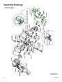
Assembly Drawings
B-510 Chopper
REVISION D
18
GC-1021B
Assembly Drawings
B-510 Chopper
Part
Number
Description
Part
Number
Description
378
FELT OILER
B-510-17
COMPRESSION SPRING
13076-10
O-RING
B-510-18
COMPRESSION SPRING
13076-11
O-RING
B-510-19
5(7$,1,1*5,1*
16828-01
5(7$,1,1*5,1*
B-510-20
*8$5'&$67,1*
17390-01
635,1*:$6+(5
B-510-21
TURN KNOB
7486-03
:$6+(5
B-510-22
CHOPPER CHUTE
7606-05
O-RING
B-510-23
SCREW
7734-06
/2&.:$6+(5
B-510-24
COVER INSERT
8160-08C
SET SCREW
B-510-25
LQ&877,1*+($'%/$'(
8160-12C
SET SCREW
B-510-71
&877(563$5(3$576.,7
8212-12F
SCREW
GC-1021
86(50$18$/
8212-16F
SCREW
9944-12C
SCREW
9944-16C
SCREW
9944-36C
SCREW
21568-00
Description
Qty.
CHOPPER MUFFLER ASSEMBLY
Part
Number
23531-02
SHOULDER SCREW
21561-00
LOCK NUT
1
23535-01
61$35,1*
21562-00
)(/7:$6+(5
2
$0
$,502725$66(0%/<
21563-01
SPEED KNOB
1
%$
$,50272563$&(5
21564-00
MUFFLER TUBE
1
B-210-16F
61$35,1*
21567-24F
SCREW
1
B-210-17
&877,1*+($'%/$'(
7486-23
:$6+(5
1
%$
LOCK NUT
%$
THUMB SCREW
B-210-32B
CONTROL BLOCK NUT
B-310-4
CUTTER CLIP
B-410-01
$,50272578%(
B-410-02-3
187&$3
B-410-07
7((6:$*(3,3(),77,1*
B-510-01
%$&.3/$7(
B-510-02
SLIDING LOCK
B-510-03
$'-8670(17.12%
B-510-04
$'-8670(17:$6+(5
B-510-05
)(('%$5
B-510-08
/$5*(:+,7(58%%(5:+((/
B-510-09
ROLLER HUB
B-510-11
,'/(5%($5,1*
B-510-14
$1*/(:('*(&877(5+($'
B-510-15
$1*/(:('*(,16(57
B-510-16
BLOWER TUB
GC-1021B
REVISION D
19
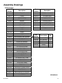
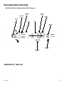
Sub-Assembly Drawings
AM-100 Air Motor (Used with B-410 Chopper)
AM-109
AM-109
Gasket
Gasket
AM-114
AM-115
Front Cap
5133-62MD
Rear Cap
AM-113
Snap Ring
Seal
N/A
N/A
AM-112
Bearing
B-210-23
Tire Shaft
NOTE:
End Cap
(Not Shown)
N/A
B-210-23A
Roll Pin
AM-110
R oll Pin
AM-103
Rotor Vane
REVISED 2/98
REPAIR KIT: AM-120
20
GC-1021B
Sub-Assembly Drawings
AM-100-2 Air Motor (Used with the B-510 Chopper)
AM-109
AM-109
Gasket
G asket
AM-114
AM-115
Front Cap
Rear Cap
AM-113
Seal
N/A
N/A
AM-112
Bearing
NOTE:
End Cap
(Not Shown)
N/A
AM-110
R oll Pin
AM-103
Rotor Vane
REPAIR KIT: AM-120
GC-1021B
21
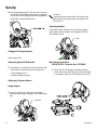
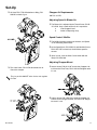
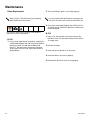
Maintenance
Blade Replacement
Refer to Figure 7 illustration during the following
Blade Replacement instructions.
2. To re-insert Blades, place in slot, sharp edge out.
It is very important that the Blade be held against the
VLGHRIWKHVORWZKLFKZLOOFRQWDFWWKH$QYLO5ROOHU¿UVW
3. 1H[WSODFHLQWKH%ODGH5HWDLQHU%DU31%$
Mask FilterEar
Use extreme caution when replacing cutter blades to
avoid severe injury or amputation.
B-410
1. Using a small slotted-blade screwdriver, carefully pry
RXWWKH%ODGH5HWDLQHU%DU31%$5HWDLQHU
Bar Spring, P/N B-210-16B and the Blade, P/N
B-210-17. Be careful not to lose these small parts
as they come free of the slot. Clean slots before replacing Blades.
and install Spring, P/N B-210-16B with a screwdriver or
needle-nose pliers.
B-510
1. 8VLQJD´$OOHQ:UHQFKORRVHQDQGUHPRYH31
B-510-23 screw. This will allow removal of P/N, B-51015 wedge insert.
2. Remove old blade.
3. Clean slot on P/N, B-510-14 as necessary.
4. Install new blade. Set insert in properly.
5. Reinstall P/N, B-510-23 screw and snug tightly.
22
GC-1021B
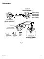
Maintenance
CORRECT
BLADE ASSEM BLY
LARGE RECTANGULAR
NOTCH VISIBLE
BLADE
CUTTER
HEAD
BLADE RETAINER BAR
THIS MUST BE VISIBLE
WHEN GUARD ASSEMBLY
IS REMOVED.
CUTTER
HEAD
RETAINER BAR SPRING
INCORRECT
BLADE ASSEM BLY
INSTALL BLADE FROM
THIS POSITION ONLY!
BLADE
BLADE RETAINER BAR
RETAINER BAR SPRING
SMALL NOTCH
THIS SIDE OF ASSEM BLY
MUST FACE CUTTER PLATE
CUTTER
HEAD
CUTTER
HEAD
B-210-16A
BLADE RETAINER
BAR
B-210-16B
RETAINER BAR
SPRING
B-210-17
BLADE
CORRECT
BLADE ASSEM BLY
Fig. 7
GC-1021B
23
Maintenance
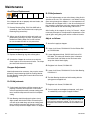
$QYLO6OHHYH5HSODFHPHQW
B-510 Adjustments
If the Chopper fails to cut properly with new blades, the
anvil roller needs replaced.
1. Remove Retaining Ring, P/N 5133-62MD with a
VFUHZGULYHU&DUHPXVWEHWDNHQQRWWRVSULQJWKH
Retaining Ring excessively.
7KH%DGMXVWPHQWVDUHVHWDWWKHIDFWRU\GXULQJ¿QDOLQspection of the unit. This adjustment is set without running
glass roving through the chopper. It is also important to remember that the chopper head is the drive mechanism of
the assembly, adjustments are being made to the Rubber
Roller, P/N B-510-08 and Idler Bearing, P/N B-510-11.
$IWHU IHHGLQJ LQ WKH VWUDQGV RI URYLQJ ³,Q 3URFHVV´ DGMXVWments may be required. This adjustment is dependent on the
type of glass roving being used and the number of strands.
2. Slide or pry off the old anvil roller and install a replacement by pressing it in place. To prevent the
EODGHVIURPPDNLQJGHHSFXWVLQUROOHU¶VXUIDFH
be sure to rotate the roller as it is pressed on.
Adjust as follows:
1. Shut off air supply to chopper.
Notice
Do not use a hammer when installing a new sleeve as
permanent damage may result.
3. Replace the Retaining ring with ordinary pliers.
4. Operate the Chopper for a minute or so with the
cover in place, to run the new anvil roller. The Chopper should now start and run freely.
Chopper Adjustments
Should adjustments be necessary, they may be accomplished by simply loosening either the Cutting Head or
WKH,GOHU%HDULQJURWDWLQJWKH(FFHQWULF1XWLQWKHEDFN
and retightening.
2. /RRVHQ/RFN6FUHZ31&IRUWKH5XEEHU5ROO
er, P/N B-510-08.
3. /RRVHQ$GMXVWPHQW.QRE31%IRUWKH31
B-510-08. This action will allow the glass in between
the Cutter Head and Roller to relax and move roller
away from Cutter Head slightly.
4. 5HWLJKWHQ/RFN6FUHZ31&
5. /RRVHQ/RFN6FUHZ31&IRUWKH,GOHU%HDULQJ
P/N B-510-11.
6. 7KH,GOHU%HDULQJVKRXOGQRZ¿QGLWVVHWWLQJZLWKWKH
spring pressure applied to it.
B-410 Adjustments
7. 5HWLJKWHQ/RFN6FUHZ31&
1. &XWWLQJKHDGVKRXOGKDYHVXI¿FLHQWVTXHH]HWRFXW
SURSHUO\([FHVVLYH$QYLO6TXHH]HRUUROOLQWHUIHU
ence will overload the motor or create starting probOHPV,QVXI¿FLHQW6TXHH]HZLOOUHVXOWLQLQFRPSOHWH
cutting.
8. Turn air supply on to chopper and operate, verify glass
LVFRQVLVWHQWO\FXWWROHQJWK&KRSSHU$LU0RWRU
Notice
2. Idler Bearing should be adjusted so there is only
VOLJKWFRQWDFWZLWKWKH$QYLO5ROOHU([FHVVLYHSUHV
sure will create motor drag and cause starting probOHPV,QVXI¿FLHQWVTXHH]HZLOODOORZWKHURYLQJQRW
to feed or drop out of the chopper when it is stopped.
24
The clearances in this Motor range are from 0.0015 to
0.002 and are extremely critical. For this reason, it is
advisable that the Motor NEVER be disassembled in the
shop!
GC-1021B
Maintenance
Model B-410 / B-510
7KH$LU0RWRURQ\RXU&KRSSHULVSUHFLVLRQEXLOWDQG
under normal operation will last hundreds of hours of
continuous use with proper care. It is recommended that
WKH2LOHU)HOW31EHOXEULFDWHGZLWK$LU0RWRU2LO
P/N 562. Depending on use, it is generally recommended that two or three drops of oil be placed on the Felt
every other day.
%HIRUHFXWWLQJJODVV
5(/,(9($,535(6685(72&+233(5
2) Remove Chopper Guard and carefully wipe clean
H[FHVVRLORQ*XDUG$QYLO6OHHYHHWF
3) Replace Guard.
GC-1021B
25
Accessories
B-510-71 Repair Kit
Part
Number
Description
Qty.
B-510-25
%/$'(6
100
B-510-08
/$5*(:+,7(58%%(5:+((/
1
B-210-71 Repair Kit
Part
Number
Description
Qty.
B-210-17
%/$'(6
100
B-210-21W
60$//:+,7(58%%(5:+((/
1
5133-62MD
61$35,1*
2
AM-120 Repair Kit
Part
Number
Description
Qty.
$0
9$1(
8
$0
*$6.(7
2
$0
%($5,1*
2
$0
6($/
1
7606-17
O-RING
1
Chopper Snout Options
Part
Number
26
Description
Gun
23543-00
OPEN SNOUT
,1'<)2508/$
23543-01
CLOSED SNOUT
,1'<)2508/$
23543-02
OPEN SNOUT
INDY X
B-210-91
&/26('612871$552:
/3$,1'<)2508/$
B-210-92
CLOSED SNOUT (WIDE)
/3$,1'<)2508/$
GC-1021B
Technical Data
GC-1021B
Category
Data
0D[LPXP$LU,QOHW3UHVVXUH
100 psi (0.7 MPa, 7 bar)
Maximum Fluid temperature
100° F (38° C)
Dimensions B-410
6.93 L X 5.32 W X 3.84 H (176.02 X 135.13 X 97.54 mm)
Dimensions B-510
6.90 L X 5.52 W X 5.67 H (175.26 X 140.21 X 144.02 mm)
Weight B-410
2.75 Lbs.
Weight B-510
3.05 Lbs.
Sound Pressure B-410
G%$
Sound Pressure B-510
G%$
Sound Power, measured per ISO 9614-2 B-410
G%$
Sound Power, measured per ISO 9614-2 B-510
G%$
27
Graco Ohio Standard Warranty
Graco warrants all equipment referenced in this document which is manufactured by Graco and bearing its name to be free from defects in
material and workmanship on the date of sale to the original purchaser for use. With the exception of any special, extended, or limited warranty
published by Graco, Graco will, for a period of twelve months from the date of sale, repair or replace any part of the equipment determined by
Graco to be defective. This warranty applies only when the equipment is installed, operated and maintained in accordance with Graco’s written
recommendations.
This warranty does not cover, and Graco shall not be liable for general wear and tear, or any malfunction, damage or wear caused by faulty installation, misapplication, abrasion, corrosion, inadequate or improper maintenance, negligence, accident, tampering, or substitution of non-Graco
component parts. Nor shall Graco be liable for malfunction, damage or wear caused by the incompatibility of Graco equipment with structures,
accessories, equipment or materials not supplied by Graco, or the improper design, manufacture, installation, operation or maintenance of
structures, accessories, equipment or materials not supplied by Graco.
This warranty is conditioned upon the prepaid return of the equipment claimed to be defective to an authorized Graco distributor for verification of
the claimed defect. If the claimed defect is verified, Graco will repair or replace free of charge any defective parts. The equipment will be returned
to the original purchaser transportation prepaid. If inspection of the equipment does not disclose any defect in material or workmanship, repairs
will be made at a reasonable charge, which charges may include the costs of parts, labor, and transportation.
THIS WARRANTY IS EXCLUSIVE, AND IS IN LIEU OF ANY OTHER WARRANTIES, EXPRESS OR IMPLIED, INCLUDING BUT NOT LIMITED TO WARRANTY OF MERCHANTABILITY OR WARRANTY OF FITNESS FOR A PARTICULAR PURPOSE.
Graco’s sole obligation and buyer’s sole remedy for any breach of warranty shall be as set forth above. The buyer agrees that no other remedy
(including, but not limited to, incidental or consequential damages for lost profits, lost sales, injury to person or property, or any other incidental
or consequential loss) shall be available. Any action for breach of warranty must be brought within two (2) years of the date of sale.
GRACO MAKES NO WARRANTY, AND DISCLAIMS ALL IMPLIED WARRANTIES OF MERCHANTABILITY AND FITNESS FOR A PARTICULAR PURPOSE, IN CONNECTION WITH ACCESSORIES, EQUIPMENT, MATERIALS OR COMPONENTS SOLD BUT NOT MANUFACTURED BY GRACO. These items sold, but not manufactured by Graco (such as electric motors, switches, hose, etc.), are subject to the warranty,
if any, of their manufacturer. Graco will provide purchaser with reasonable assistance in making any claim for breach of these warranties.
In no event will Graco be liable for indirect, incidental, special or consequential damages resulting from Graco supplying equipment hereunder,
or the furnishing, performance, or use of any products or other goods sold hereto, whether due to a breach of contract, breach of warranty, the
negligence of Graco, or otherwise.
FOR GRACO CANADA CUSTOMERS
The Parties acknowledge that they have required that the present document, as well as all documents, notices and legal proceedings entered
into, given or instituted pursuant hereto or relating directly or indirectly hereto, be drawn up in English. Les parties reconnaissent avoir convenu
que la rédaction du présente document sera en Anglais, ainsi que tous documents, avis et procédures judiciaires exécutés, donnés ou intentés,
à la suite de ou en rapport, directement ou indirectement, avec les procédures concernées.
Graco Ohio Information
TO PLACE AN ORDER, contact your Graco distributor or call to identify the nearest distributor.
Toll Free: 1-800-746-1334 or Fax: 330-966-3006
All written and visual data contained in this document reflects the latest product information available at the time of publication.
Graco reserves the right to make changes at any time without notice.
This manual contains English. MM GC-1021
Graco Headquarters: Minneapolis
International Offices: Belgium, China, Japan, Korea
GRACO OHIO INC. 8400 PORT JACKSON AVE NW, NORTH CANTON, OH 44720
Copyright 2008, Graco Ohio Inc. is registered to I.S. EN ISO 9001
www.graco.com
Revised 11/2008