1
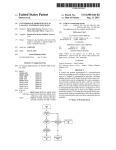
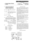
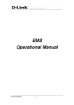
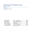
US006453210B1
(12) United States Patent
US 6,453,210 B1
Sep. 17, 2002
(10) Patent N0.:
(45) Date of Patent:
Belotserkovskiy et al.
Primary Examiner—Leo Picard
(54) AUTONOMOUS CONTROL METHOD AND
PROCESS FOR AN INVESTMENT CASTING
SHELL
Assistant Examiner—Steven R. Garland
(74) Attorney, Agent, or Firm—Robert J. Veal; Christopher
A. Holland; Burr & Forman LLP
(75) Inventors: Aleksandr Belotserkovskiy; Tao-Li
(57)
ABSTRACT
Hsu, both of Birmingham; Jack L.
Walton, Helena; Darren Ash, Pell City,
A predictive industrial control system for controlling indi
vidual cells of machines through multiple Programmable
Logic Controllers in an investment casting processing and
all of AL (US)
(73) Assignee: Vulcan Engineering Company, Inc.,
handling operation. An application server located in a
Helena, AL (US)
(*)
Notice:
remote, non-industrial environment executes an industrial
Subject to any disclaimer, the term of this
patent is extended or adjusted under 35
control application (ICA) utilizing tagged reference names
U.S.C. 154(b) by 0 days.
devices such as sensors on the production line. The ICA
corresponding to individual machines and information input
accesses local databases that hold casting shell part numbers
and their associated recipe control words, and monitors the
(21) Appl. No.: 09/121,496
(22) Filed:
system for new shell part numbers as they appear on a load
Jul. 23, 1998
(51)
Int. Cl.7 .............................................. .. G06F 19/00
(52)
US. Cl. ....................... .. 700/96; 700/146; 700/117;
conveyor in the production line. Radio Frequency tags on
the part signal the ICA to transfer the appropriate recipe
control words and robot moves required to process the part
in a primary processing cell’s PLC. The PLC then controls
each machine in the primary processing cell in accordance
with the downloaded commands from the ICA. The control
program downloaded into the PLC at boot-up is written such
that machines connected to the PLC may operate indepen
dently from the ICA during a selected number of dip cycles.
Since processing instructions are downloaded in a predictive
700/116
(58)
Field of Search ............................ .. 700/2, 7, 9, 17,
700/79, 86, 117, 96, 116, 118, 121, 146,
169, 201, 200, 83; 164/165, 166, 361
(56)
manner well ahead of any situation requiring new
References Cited
instructions, the processing of the ICA instructions on the
remote server or communications on a slow industrial net
U.S. PATENT DOCUMENTS
work does not limit the processing throughput of each cell;
4,566,061 A
4,908,746 A
*
5,325,522 A
5,517,404 A
6,145,022 A
1/1986 Ogden et al. ............... .. 700/17
3/1990 Vaughn ...... ..
364/142
6/1994 Vaughn
and therefore, the production line throughput. The system
allows for alteration of the sequence of processing steps
395/600
from automatic to manual modes as desired without seri
* 5/1996 Biber et a1. .................. .. 700/9
* 11/2000 TakiZawa et al. ........... .. 710/10
ously hampering the system throughput.
15 Claims, 12 Drawing Sheets
* cited by examiner
11
1e
16
1s
\
\
\
‘
\
1
14
l
1
1
REMOTE
WORKSTATION
|
|
|
REMOTE
WORKSTATION
1
19
REMOTE
WORKSTATION
1
1
1
LOCAL
©
OTHER
DATABASE(S)
OTHER
DATABASE
HUB/SERVER M SERVER(S)
17/
17-\
/
I
LEGEND:
41
Ethernet Links
T
110 Links
T
T
T
T
T
T
T
l
T
T
1
24
1
1
26
T
T
T
T
T
T
T
T
T
T
T
T
T1
UNIQUE TAG READING
1
1
81111121211291’
EQUIPMENT
27 53511221,
‘1
I
1T
1
1
1
1
1
1
1
|
|
T
T
|
1
1 1
1
’
1 1
1
1
1
|
|
T
T
1
T1
22
1
1 1
1
1
PLC
1 1
1
11 11
1
1T
21
PLC
51
1
1
1
1
Barth1 11
“CW1
EU‘ 1
so
28
32
31_/-1
L_
T
1
1
1
_
_
_
_
_
_
_
_
_
_
_
_
_
_
_
_
_
_
_
_
_
_
__J
1
1
L_
\32
1
1
___1
1
1
1_2
\32
l
I
_LJ
U.S. Patent
Sep. 17, 2002
Sheet 2 0f 12
US 6,453,210 B1
N.05
U.S. Patent
Sep. 17, 2002
Sheet 3 0f 12
US 6,453,210 B1
U.S. Patent
Sep. 17, 2002
Sheet 5 0f 12
US 6,453,210 B1
QUE
U.S. Patent
Sep. 17, 2002
QmIoN|._w@Iz>Q< oKmz<awEkQ
c.EoUmzFahXwomi
Sheet 6 0f 12
US 6,453,210 B1
5Q5.556woEw
zENmDI._QE
RUE
U.S. Patent
Sep. 17, 2002
Performing Robot
Sheet 7 0f 12
US 6,453,210 B1
Ready for data 1=YES, O=NO
0
15
Primary Robot P
0
14
Backup Robot A
O
13
Backup Robot B
1
12
Reserved
0
11
Reserved
0
10
PKP From Transfer Conveyor
1
9
PKP from Final Dry Conveyor
O
8
PKP from Rapid Dry Conveyor
1
7
PKP from Load Conveyor
O
6
STDN to Transfer Conveyor
O
5
STDN to Final Dry Conveyor
O
4
STDN to Rapid Dry Conveyor
1
3
STDN to Load Conveyor
0
2
Last Cycle bit 1=YES, O=NO
O
1
Hanger Has Been Erased
0
0
Pickup From ConveyoH
p
Set Down To Conveyor %
FIG. 8
U.S. Patent
Sep. 17, 2002
Sheet 8 0f 12
US 6,453,210 B1
PLC MEMORY
Memory Loc 1
CTRL Code
RF Tag
Next Dip
Current Move
Current Dry Time
Next Drytime
Hanger Status
Month
Day
Hour
4744
123
5
403
50
110
0
1
21
13
Move 1
Move 2
Move 3
Move 4
Move 5
Move 6
Move 7
Move 8
Move 9
Move 10
403
428
700
0
0
O
0
0
0
0
Minute
Pressure
Rotation
34
30
50
Move 11
Move 12
Move 13
0
O
O
Blow Off Time
15
Move
Move
Move
Move
Move
Move
Move
0
0
0
0
0
0
0
FIG. 9
14
15
16
17
18
19
2O
U.S. Patent
Sep. 17, 2002
US 6,453,210 B1
Sheet 9 0f 12
LOAD SHELL PART
CELL ROBOT
BACK CELL
AND CURRENT
ELEMENTS
I IP CYCLE MACHIN
AVAILABLE
AVAILABLE
‘.7
PICK UP PART FROM
MOVE PART TO
TRANSFER CONVEYOR
AND SEND FLAG TO
OTHER PLC
OFF-LOADING STATION
REQUEST DATABASE
TAG RESIDENT
IN SQL DATABASE
7
NO
PART NUMBER
ASSOCIATION
AND EXECUTE FIRST
DIP CYCLE ROBOT
SUB-ROUTINE COMMAND
YES
LOAD PART NUMBER
ASSOCIATED RECIPE
INTO ACTIVE
PART NUMBER
DDE DATABASE
SEND NEXT
ROBOT SUB-ROUTINE
COPY FIRST DIP CYCLE
CONTROL WORD AND
ROBOT SUB-ROUTINE
MOVES INTO
PRIMARY PLC
HAS PART
ARRNED AT
ROBOT CELL?
TO ROBOT FOR
NO
YES
SET PART DOWN
ON ANY CONVEYOR
SPECIFIED IN
CONTROL WORD
1
SET BIT NUMBER 15
IN CONTROL WORD
EQUAL TO 1
I
HAS PART
ARRIVED AT
U N-LOAD
STATION‘?
OVERWRITE CURRENTLY
LOADED DIP CYCLE INFO
IN PLC WITH NEXT
DIP CYCLE CONTROL WORD
AND ROBOT COMMANDS
FROM DDE DATABASE
NUMBER OF
CONTROL WORD
DIP CYCLES IN
EQUAL TO 1 ?
SET BIT NUMBER 1
IN CONTROL WORD
EQUAL TO 1
NO
EXECUTION
U.S. Patent
Sep. 17, 2002
Sheet 10 0f 12
US 6,453,210 B1
PATH LOCATING PROCEDURE
XFER-WAX TRANSFER CONVEYOR
BEGIN PATH LOCATING
PROCEDURE
FAST-RAPID DRY CONVEYOR
FINAL-FINAL DRY CONVEYOR
L
F
MOVE EMPTY HANGER
PROCEDURE
LOAD
MODE
OF REMOTE
CELL OPERATION
U NLOAD
LOAD-UNLOAD)
PATH ANALYSIS FOR
PICKUP=WAXIXFER
SET DN=FAST
(FINAL->FINAL)
(XFER->FAST)
(FINAL->FAST)
(XFER->XFER)
(FAST->XFER)
(FAST-> FAST)
(FAST->XF ER)
(FAST->FINAL)
(FAST->FINAL)
(FAST->XFER)
(FAST->FAST)
(FINAL->XFER)
(FINAL->FAST)
(XFER->XFER)
(FINAL->FINALT)
(XFER-> FAST)
FIG. 11
U.S. Patent
Sep. 17, 2002
US 6,453,210 B1
Sheet 11 0f 12
l___—__
CHANGE CHOSEN
PICKUP AND SETDOWN CONVEYORS
ACCORDING TO THE
PATH LOCATING PROCEDURE
AND BEGIN
PATH ANALYSIS
PICKUP
CONVEYOR
YES
AVAILABLE 7
NO
(NOT INHIBITEDNOT DOCKING,
lN POSITION.
m AUTO MODE)
FIG. 12
PATH ANALYSIS PROCEDURE
PART
ON PICKUP CONVEYOR
AVAILABLE 7
(DRYING TIME CHECK)
SETDOWN
YES
CONVEYOR
AVAILABLE 7
(NOT INHIBITEDNOT DOCKING.
IN POSITION
m AUTO MODE)
DOES SETDOWN
CONVEYOR HAVE
EMPTY HOOK AT
SETDOWN POSITION
7
ENVIRONMENT
PARAMETERS
GOOD ‘7
EMPERATURE. HUMIDITY
(CORRECT ROBOT?
WHERE TO PICK UP?
HANGER
DISABLED 7
(BROKEN, BENT, ETC.)
_———I
INHIBIT
PICKUP AND SETDOWN
OONVEYORS,
DIP THE PART,
RELEASE INHIBITION
END OF PROCEDURE
F
CHOSEN COVEYORS
YES
U.S. Patent
Sep. 17, 2002
Sheet 12 0f 12
US 6,453,210 B1
BEGIN
HANGER RETURN
PROCEDURE
FINAL
CONVEYOR
YES
AVAILABLE ?
(NOT |NH|B|TED,NOT DOCKING.
IN POSITION.
IN AUTO MODE)
FIG. 13
EMPTY HANGER RETURN PROCEDURE
YES
EMPTY HANGER
ON
FINAL CONVEYOR
AT
PICKUP POINT 7
YES
WAX XFER
CONVEYOR
AVAILABLE 7
(NOT INHIBITED,NOT DOCKING.
IN POSITION.
IN AUTO MODE)
YES
DOES WAX XF ER
CONVEYOR HAVE
EMPTY HOOK AT
SETDOWN POSITION
7
SETDOWN
HOOK
DISABLED
7
'—I.
MOVE
EMPTY HANGER
PROCEDURE
END OF
EMPTY HANGER
MOVING PROCEDURE
NO
US 6,453,210 B1
1
2
AUTONOMOUS CONTROL METHOD AND
PROCESS FOR AN INVESTMENT CASTING
SHELL
part. Also, multiple conveyors must move in a coordinated
effort, sometimes throughout a large facility, to and aWay
from each processing cell.
Previously, during the evolutionary advancement of
industrial controls, robot manipulators and other processing
machines included relatively simple programmable memory
FIELD OF THE INVENTION
The present invention relates generally to industrial con
Which Was preprogrammed to initiate tasks in response to
trol systems. In particular, the invention pertains to control
methods for investment casting shell handling systems, and
external conveyor sensors. Little or no communication
methods of autonomous control of groups of machines
through a programmable logic controller.
10
autonomous and acted as a master With respect to any
connected programmable logic controllers (PLCs). The
BACKGROUND OF THE INVENTION
PLCs Were simply programming conduits through Which
individual robots could be programmed.
Investment casting systems have recently increased in
complexity to fabricate more intricate and complex metal
parts. In the past, producing an investment casting required
15
nected through PLCs. In these types of “real-time” systems,
20
completed. Mainly, these steps consisted of pouring sand
sisted of operator initiated sWitching and preset loading
operations based upon gondola positioning. Intelligent con
tions through the PLCs, Which act as a bi-directional pass
25
from resident electromagnetic pulse (EMP) interference.
30
of ceramic materials are built up around a sacri?cial Wax or
foam mold. These shells fully encase the mold and func
35
viously used. Once a suitable shell is created around the
mold, molten metal is poured directly into the shell through
sacri?cial core is molten or vaporiZed and the shell is
40
process.
Building up the successive layers of ceramic material
around the mold requires a sequence of repetitive steps of
dipping the molds into various mixtures of glue/cement
slurries and then surrounding the coated mold With ?uidiZed
sand and drying. The duration and environmental conditions
of each drying step, in conjunction With the type of sand
applied to the specialiZed slurry coating greatly affects the
properties of the ?nal shell created. Therefore, speci?c
“recipes” are designed for each particular casting shell part
For complex investment casting shell handling operations
in Which doZens of machines, sensors, and conveyors, in
doZens of different processing cells must communicate,
45
Moreover, complex processing in an application server or
distributed PLCs dependent upon real-time commands from
50
a control application running on the server.
From the foregoing, modem casting shell systems require
an information topology and method in Which complex
processing can be removed from the factory ?oor and
commands automatically distributed to PLCs on the factory
55
shell in accordance With a speci?ed recipe. Furthermore,
different types of shells for casting different types of metal
?oor in a predictive manner, and from Which sensor and
status information can be retrieved and displayed at remote
locations. In effect, a need exists for a factory processing
system in Which distributed PLCs on the factory ?oor
become individual master controllers over machines in
60
turing of the various types of shells on one assembly line,
“cells” of processing machines must be able to automatically
recogniZe What type of shell has entered the production line
and automatically con?gure their processing steps in accor
dance With a particular recipe associated With the shell part.
Typically, this Will entail automatic recognition of the shell
part through radio frequency or bar coded tags affixed to the
factory ?oor netWorks limit the processing poWer of the
CPU accessing the real-time data from the ?oor netWork.
PC results in limiting factory ?oor operations by making the
shell manufacturing is complex. Robot manipulators, ?uid
parts are often made on the same shell assembly line,
utiliZing the same machines. In order to automate manufac
PLCs. HoWever, older, more reliable netWorks, such as the
DH+ are the norm, and the added shielding expense and
increased error rates are prohibitive.
to achieve each shell’s desired properties.
Due to the many variations Within recipes, automation of
iZed barrels or rainfall sanders, temperature controlled ven
tilation fans, and conveyors carrying Wax or foam molds
must Work in a coordinated effort to make a desired casting
This is sloW in contrast to the nominal local area netWorks
Which transmit data a 10 to 100 Mbits/sec rate. Currently,
With the addition of proper shielding, such netWorks are
beginning to be installed directly on the factory ?oors
alloWing increased data communications rates betWeen
a shaped cemented into the shell during its fabrication. The
extracted from the neWly cast part during the clean-up
Furthermore, factory ?oor data communications necessitates
multiple error correcting protocols and hinders the speed at
Which data may be transmitted. For example, Allen Brad
ley’s Well knoWn Data HighWay PlusTM netWork transmits
data at 240 k bits/sec for netWorks extending to 10,000 feet.
alloys. Today, casting “shells” made up of successive layers
tionally replace the bulky gondola and sand supports pre
through multiplexer to Which multiple robot and machines
might be connected.
HoWever, high speed complex processing on a factory
?oor tends to be less reliable than remote processing aWay
trol Was a human operator initiating each machine in
sequence based upon knoWn timing constraints.
HoWever, investment casting steps have evolved to be
able to produce far more complex parts using a variety of
a processor, typically the CPU in a Personal Computer
located on the factory ?oor, accesses data elements in a
resident database and in response issues commands to the
machines through the PLCs. In these neWer arrangements,
machines and manipulators receive their movement instruc
processing step of the casting Within the gondola carrier Was
into the gondola to surround the sacri?cial mold and then
pouring a metal alloy into the mold. Control systems con
In response to the necessity to coordinate robot and
machine actions, neWer systems have included real-time
databases on the factory ?oor to Which machines are con
the relatively simple steps of surrounding a Wax or foam
mold With sand in a gondola into Which the molten metal is
poured in a sacri?cial or molten replacement of the mold.
Automation consisted of moving a gondola mounted on a
railed conveyor to a particular station at Which a particular
occurred betWeen each machine and overall system level
control rudimentary. These machines Were therefore mostly
associated individual processing cells, and from Which a
remote industrial control application server may service a
plurality of individual master PLCs on a factory ?oor at the
request of an individual PLC.
65
SUMMARY OF THE INVENTION
It is the object of the present invention to provide a
predictive industrial control system in Which a computer
US 6,453,210 B1
4
3
FIG. 2 is system diagram of a typical investment casting
server can access and process information from local and
remote databases and then pass groups of commands to
conveyor system With multiple processing cells;
programmable logic controllers on a factory ?oor upon
request.
FIG. 3 is an magni?ed vieW of a processing cell shoWing
its individual components;
Another object of the present invention is to provide an
autonomous control topology in Which groups of commands
may be doWnloaded into programmable logic controllers on
recipe listing shoWing casting part descriptions and their
FIG. 4 is a screen display from the ICA of a representative
associated recipe numbers saved in the SQL database;
the factory ?oor for controlling connected machines.
Afurther object of the invention is to provide an industrial
control system in Which programmable logic controllers on
the factory ?oor act as master controllers for cells of
10
processing commands.
commands and their associated descriptions;
FIG. 7 shoWs another screen display listing a second
15
Another object of the present invention is to provide
subset of robot commands and their associated descriptions;
FIG. 8 is an eXample control Word resulting from an
individual dip cycle displayed in FIG. No. 5;
processing scalability of multiple processing cells in
FIG. 9 is a formatted listing of a subset of the contents of
response to increased production activity.
And yet another object of the present invention is to
provide distributed processing on an industrial production
the PLC memory shoWing the memory image of a logical
device;
FIG. 10 is a logical ?oW diagram shoWing the sequence
line through multiple programmable logic controllers.
of actions of a cell in response to the loading and arrival of
a casting mold part at the cell for processing;
In summary, the invention is an industrial control system
for controlling individual cells of machines through multiple
PLCs in an investment casting processing and handling
tive casting part;
FIG. 6 shoWs a screen display listing a subset of robot
connected machinery.
A still further object of the present invention is to provide
a unique control Word format or encoding casting shell
FIG. 5 is a screen display of the individual dip cycles and
associated robot commands and dry times for a representa
25
operation. An application server located in a remote, non
industrial environment eXecutes an industrial control appli
FIG. 11 is a logical ?oW diagram shoWing the sequence of
path analysis procedure application (see FIG. 12);
FIG. 12 is a logical ?oW diagram shoWing the Path
Analysis Procedure; and,
cation (ICA) utiliZing tagged reference names correspond
FIG. 13 is a logical ?oW diagram shoWing the empty
ing to individual machines and information input devices
hanger return procedure.
such as sensors on the production line. The ICA accesses
local databases including a Dynamic Data Exchange (DDE)
DESCRIPTION OF THE PREFERRED
EMBODIMENTS
database for holding PLC control status information and a
Structured Query Language (SQL) database for holding
casting shell part numbers and their associated recipe control
For purposes of illustration the present invention Will be
Words. The ICA monitors the DDE database and as a neW 35 described in With reference to an investment casting core
coating operation; hoWever, it is to be understood that the
shell part number appears on a load conveyor in the pro
duction line, Radio Frequency (RF) tags on the part update
invention may be utiliZed in other materials handling appli
the DDE database and signal the ICA to transfer the appro
priate recipe control Words and robot moves required to
cations Wherein distributed control netWorks can be
process the part to the primary processing cell’s PLC. The
Referring to FIGS. 1 and 2, a prefabricated core C is input
employed.
PLC then controls each machine in accordance With the
doWnloaded commands from the ICA. The control program
doWnloaded into the PLC at boot-up is Written such that
machines connected to the PLC may operate independently
into the system at a loading station on a hanger to be carried
by a load conveyor 24 Which may have any number of
hangers and cores thereon at any given time. Sensor such as
a photo scan, bar code, RF scanner immediately reads a
from the ICA during a selected number of dip cycles. Since 45 “tag” on the core hanger. Load conveyor 24 delivers core C
processing instructions are doWnloaded in a predictive man
to a primary processing cell 31 Where core C is to be coated
ner Well ahead of any situation requiring neW instructions,
as referred to above. Primary processing cell 31 includes a
the processing of the ICA instructions on the remote server
robotic manipulator 33 under the control of a primary
or communications on a relatively sloW multiple error
processing cell programmable logic controller (PLC) 13.
correcting protocol netWork such as DH+ does not limit the
tion line throughput. Furthermore, the system alloWs for
Robotic manipulator 33 is positioned to move a hanger and
associated core selectively to positions Within its reach
Where a variety of processing units, the function of Which
alteration of the sequence of processing steps from auto
matic to manual modes at Will Without seriously hampering
more slurry tanks 36 having a predetermined coating com
processing throughput each cell; and therefore, the produc
the system throughput.
are Well knoWn in the industry, are located including one or
55 position therein, one or more barrel sanders 43, one or more
Other features and objects and advantages of the present
rainfall sanders 38, and a pre-Wet tank 37. Manipulator 33
system Will become apparent from a reading of the folloW
ing description as Well as a study of the appended draWings.
can also position the hanger and core at a pick up Zone for
placement onto a rapid dry conveyor 27, a ?nal dry conveyor
28, or a transfer conveyor 26. One or more back-up pro
BRIEF DESCRIPTION OF THE DRAWINGS
cessing cells 41, 51 are provided having all of the compo
nents described With reference to primary cell 31, eXcept that
An investment casting shell handling and processing
control system incorporating the features of the invention is
depicted in the attached draWings Which form a portion of
the disclosure and Wherein:
FIG. 1 is a topological diagram shoWing the different
logical elements of the control system and the relative How
of information betWeen them;
65
transfer conveyor 26 is common to all processing cells. In
FIG. 2, the ?nal dry conveyor 28 at cell 31 is not shoWn in
the interest of claimant. The ?nal conveyor 28 of each
processing cell connects to an Unload station 60. Each
processing cell has its oWn PLC Which controls the manipu
lator and processing units described; hoWever, Transfer
US 6,453,210 B1
5
6
conveyor 26 is under the control of PLC 13 of the primary
processing cell 31. An exemplary PLC suitable for the
purposes of the present invention is the Allen Bradley
system to identify and track hangers in the system. The
output of these sensors can be used as control signals or
database entries to the DDE database.
Referring to FIG. 1 for a better understanding of the
SLC-500, 5/05 series. Arobotic manipulator suitable for the
purposes of the present invention is an IRB 4400 manufac
function and structure of the invention, the control system 10
includes an industrial control application (ICA) running on
an application server 11. The ICA includes capability for
tured by Asea BroWn Boveri. For the purposes of the present
invention a manipulator is required Which has on-board
memory and processing such that a number of movements
can be “taught” to the robot and stored in memory for
selective recall. These taught movements are the building
blocks for the system as hereinafter described.
tagging and communicating With various elements Within
10
The various components hereinabove described are con
nected by a netWork 17, that is to say, electrical connections
for passing data and control signals to and betWeen various
components. Typical connections betWeen PLC’s and units
the system. The ICA also has the capability to access
multiple databases simultaneously and alloW a user to alter
the system’s function and input neW information in the
databases on the ?y. One example of an ICA capable of
accomplishing these goals is the industrial control program
InTouchTM produced by WonderWare® Inc. Running under
15
a Microsoft® WindoWsTM operating system, InTouchTM
alloWs for the creation of a graphical man-machine interface
under their control Will be by serial connection such as
RS-232 or RS-485 links, Ethernet®, or other suitable links.
The PLCs Will also be connected to each other by such links.
(MMI) shoWing the investment casting system’s compo
A description of the physical interconnection is not deemed
necessary, such being Well knoWn in the art.
With the foregoing system components operably con
nected to process cores from the loading station through the
processing cell to the unload station, the novel features of
processing recipes (see FIG. 5) may be created for each
the invention Will noW be described. It should be understood
that each movement of a robotic manipulator is stored at the
nents. Each graphically represented component has an
assigned address tag name compiled into a data dictionary
for storing of all system components in a database. Also,
casting part that is to be produced that contains a sequence
of control Words (see FIG. 8) that are in turn doWnloaded
into an appropriate Programmable Logic Controller (PLC)
25
robot and can be electronically retrieved and replicated by
the robotic manipulator upon an appropriate coded com
mand from the associate PLC. LikeWise, each processing
13 at the appropriate time (See FIG. 9). The format of the
screens in the MMI, the data correlation functions, tag
names, control functions, the database formats, and the
general system interaction among the communicating com
unit can be activated, indexed, or otherWise appropriately
controlled by the PLC. Each type core and shell component
Will have a different processing sequence Which consists of
a plurality of movements of the manipulator and associated
ponents through the ICA, including the data Word formats,
actions by the processing units called dip cycles and drying
(DDE) and Structured Query LanguageTM (SQL) databases
are designed by the user and are not pre-created by the ICA.
In addition to an MMI, InTouchTM includes utility programs
to interface With and export to Dynamic Data ExchangeTM
times after each dip cycle. Knowledge of the resident robotic
movements and the retrieval codes alloWs the cell and the
units therein to be controlled based on the type core and shell
desired. To achieve a distributed control netWork Which
35
alloWs seemingly autonomous Work by each cell, We have
in local database 14. The parts recipes are typically stored in
the local SQL database, and component interface commands
and component status are typically stored in the DDE
database. Storing the ICA information in DDE and SQL
compliant database, such as Microsoft AccessTM or
devised a control netWork including a server 11, Wherein an
OracleTM, alloWs remote access and manipulation of system
industrial control application or program is stored and
executable, a local database 14 in Which a dynamic database
information from remote points on the netWork. Given a
functional WindoWsTM netWork, remote client Work stations
memory in Which a dynamic database exchange (DDE)
database is maintained, and a Structured Query Memory in
Which a Structured Query Language (SQL) database is
maintained. The SQL database contains core part numbers
and control Words as described hereinafter. The DDE data
16 running restricted client InTouchTM softWare can access
the database across a high-speed netWork, such as an Eth
45
connected to a PLC on the factory ?oor. Client nodes are not
base contains constantly updated status information from
each cell and conveyor. Each hanger has machine readable
necessary for the control systems operation; hoWever, they
alloW for increased ef?ciency for additional Workers to
prepare neW recipes in accordance With installed factory
?oor components. Other applications not a part of the
indicia on it, eg bar code, RF Tag. Inasmuch as each type
core Will have a speci?c processing sequence, information
on the sequence can be used to de?ne Which processing units
are required to perform their operation on the core. By
digitally de?ning each processing cell and certain of its
components a control Word can be generated Which carries
encoded information about Which robot is alloWed to
ernet® netWork, develop and load neW recipes for neW
casting parts, and display the current status of machines
55
execute a particular dip cycle and Which conveyor the
particular type core is to be picked up from and set doWn on.
novelty of the present invention may be stored and run on
other application servers 18 Which may access, in turn, other
databases 19 present on the netWork. Further discussion as
to the Working of the WindoWTM interface and a description
as to interaction Within the WindoWsTM operating system
betWeen the databases and the ICA are omitted inasmuch as
this information is Well understood in the industry and not
A recipe for each type core is thereby de?ned by the
sequence of dip cycles and the code Word for the core. For
pertinent to an understanding of the present invention.
each type core to be handled by the system a recipe is stored
in the SQL database. Accordingly, the recipe for a core can
be associated With the hanger bearing it by the indicia on the
referenced softWare and hardWare components are readily
available from a reading of the references citedin this
hanger.
Communication from the application server 11 to indi
vidual PLCs on the factory ?oor is accomplished over any
Further information regarding the operation of individually
speci?cation.
LikeWise, by de?ning each position in the system and
each hanger by its indicia, the DDE database may be
constantly updated to provide information about the status of
the entire system. Sensors can be located throughout the
65
number of user selected netWorks. As may be seen in FIG.
1, communications links from the server 11 to the PLCs 13,
21, 22 may be high speed netWorks if the connected PLC has
US 6,453,210 B1
7
8
such capability. Application servers often have an installed
interface card as for eXample a 5136-SD manufactured by
S-S Technologies, Inc. so that communication to the PLCs
may be seamlessly accomplished over a local netWork While
associated With the particular part to the primary cell PLC
betWeen the server and individual PLCs in the system,
13. PLC 13 controls all of the machines associated With
processing a part in its cell via the local I/O netWork. PLC
13 also controls the load conveyor 24 and the transfer
conveyor 26, and maintains a complete mold parts image of
each part loaded on any of its conveyors, including the
transfer conveyor 26. Back-up cells A 41 and B 51 process
shell parts in accordance With the primary cells’ inability to
higher speed communications over Ethernet® type netWorks
process a dip cycle for a part loaded on a conveyor con
maintaining higher speed Ethernet® communications
among higher level processing elements such as databases
14 and client nodes 16. Regardless of the connection method
among remote components such as the databases, servers,
and client nodes Would remain.
One PLC having the capability to communicate to a
server over a high speed Ethernet® netWork is the Allen
10
that the primary cell is busy or does not have a processing
machine available for the neXt dip cycle. Each PLC in the
back-up cells A 41 and B 51 control their oWn adjacent set
Bradley SLC-500, 5/05 series Which is Well knoWn and Well
understood in the industrial control art. Further references to
15
of their cell’s processing machines. The primary PLC 13
also controls these elements in its oWn cell.
As seen in FIG. 3, each cell consists of a grouping of
trial controller. Most industrial controllers either emulate or
machines connected to a master cell PLC (13, 21, 22). Each
machine communicates With their respective master PLC via
a local I/O netWork 32 as previously described. A central
simulate SLC-500, 5/05 type features.
Local I/O communications (32) from PLC to PLC, PLC
to a cell robot, PLC to conveyors, and PLC to other cell
robot 33 moves Wax or foam molds from the load conveyor
24 at the off-load station 34 and to a processing machine as
processing machines may be accomplished via RS-232,
25
dictated by a dip cycle held in individual shell part recipes,
Which are doWnloaded via the ICA into the PLC 13. As is
tions occur asynchronously relative to communications With
the ICA on the server. In an operational system using all of
the above components, the ICA can obtain and Write to the
DDE database a complete image of each PLC’s memory
contents. The combination of the data dictionary tags With
the system DDE PLC memory images alloWs the ICA to
display and process information obtained from all compo
nents in the system at any instant.
Referring to FIG. 2 for a better understanding of typical
system components in an investment casting operation, a
of rapid dry and ?nal conveyors, any environmental equip
ment surrounding the conveyors, and the initiation of each
PLC internal elements and capabilities shall be made With
respect to the Allen Bradley SLC series Which has set
industry standards through its Wide acceptance as an indus
RS-485, or DH+ communication links depending upon
installed adapter cards in each PLC. Local I/O communica
trolled by PLC 13. As Will be seen, back-up cells may
perform interim dip steps in a particular recipe in the event
Well knoWn in the industry, various types of machines are
used in each cell of a casting shell processing plant. Pre-Wet
37 and slurry tanks 36 supply premiXed coatings into Which
a casting mold is dipped so that sand or other particulate
materials Will adhere to the mold. Rainfall 38 and barrel 43
sanders provide a means for ?uidiZing sand around a mold
so that all surfaces of the coated mold are covered With sand
(or other particulate material) Without damaging it. Rapid
35
system of conveyor loads 24, transfers 26, and holds (27—28)
parts for drying as they proceed through the plant. In a
dry conveyors 27 convey coated parts to climate controlled
rooms for drying betWeen dip cycles in accordance With
pre-selected drying conditions. And ?nal dry conveyors 28
casting shell handling system, special hangers hold the mold
move completed shells to an unloading area 60 and for
eXtended drying. Further comment as to the use and opera
parts to be processed on an elevated conveyor to facilitate
tion of individual machines used in the processing of casting
processing and handling by robots. The load conveyor 24
shells Will be omitted inasmuch as it is not pertinent to an
has sensors for reading radio frequency tags or bar coded
understanding of the present invention.
tags on the Wax or foam mold parts as they are loaded. Also,
photo sensors are present at pickup and set doWn points on
conveyors adjacent to robots so that a robot knoWs through
its communication With the PLC Whether a hanger holding
Referring noW to FIG. 4, it may be seen that the ICA may
45
one or more shell parts is presently at a pickup or set doWn
position.
Through the MMI on the application server’s Workstation
or on a remote client node, an operator associates the casting
part’s tag number With a particular casting part description
already resident and loaded in the SQL parts database.
Typically, the association process may be done Well ahead of
the time of actual loading of the part on the loading
conveyor; hoWever, an operator may also associate the tag
number With a part description via a remote terminal adja
cent to the entry point of the part at the loading conveyor 24.
conveyor, and a series of associated robot commands pre
55
Alternatively, the operator may simply enter the part number
af?Xed to the mold part Which has already been associated
in the SQL database from Which part number association
Will occur automatically in the ICA. Tag numbers entered
and associated either at time of loading or prior are stored in
the remote database 14 for access by the ICA over the high
stored in the applicable cell robot’s memory. By Way of
eXample, dip cycle 3 for recipe No. 11345 for a vane
segment indicates that backup robot 52 of cell B (51) Will
execute robot subroutines 403, 428, and 700. Robots used in
casting operations have their oWn on-board memory storage
and processing for robot moves. Various types of teach
pendant applications alloW for the storage of various robot
moves in the robot memory. A succession of moves in a
pre-selected coordinate system may also be stored in the
speed netWork.
After loading a selected part on the load conveyor 24, the
ICA recogniZes that a part has been loaded on the load
conveyor 24 and doWnloads the processing information
be programmed With a multitude of casting shell recipes.
The listing shoWs a speci?c recipe number, the maXimum
number of dip cycles, and a description of the metal part that
Will be created in the completed casting shell. The ICA
alloWs selection and editing of a particular recipe as for
eXample the vane segment part as listed in FIG. 5 shoWing
its associated recipe No. 11345. As shoWn in the ?gure,
individual dip cycles are broken doWn in ?elds listing the
applicable cell robot, Which conveyors the shell shall be
retrieved from and delivered to, dry times on the applicable
robot’s memory as numbered subroutines and referenced for
65
eXecution by number.
A typical robot used in casting shell handling systems is
an IRB 4400 manufactured by Asea BroWn Boveri
US 6,453,210 B1
10
Arobot from the IRB 4400 series has its oWn computing and
I/O resources similar to a PC, and usually includes pre
current move number, current and next dry times, a hanger
loaded high-level application-oriented programming lan
guage interpreters and debug procedures for creating sepa
for the dip cycle, and some environment information such as
rate numbered robot movement subroutines. For example, as
pertinent to the process of dipping the mold part.
status bit (0=enable, 1=disable), the prescribed robot moves
temperature, relative humidity, speed of drying fans, etc.,
shoWn in FIG. 6, subroutine 403 in dip cycle No. 3 com
PLCs such as the Allen Bradley 500 series separate
memory allocation into processor image ?les and scanner
I/O image ?les. This type of architecture alloWs a PLC to
continually update its scanner I/O memory in discrete trans
mands the robot’s arm to move the 11345 shell into a
concrete slurry tank for a predetermined soaking period.
Subroutines 428 cause the robot to execute a series of moves
to accomplish a draining procedure from the slurry tank, and
10
700 (FIG. 7) causes the shell to be saWdusted. As shoWn in
FIG. 9, the drying time prior to proceeding to the next dip
cycle is 50 minutes. Each of these robot subroutines Were
created and stored speci?cally to accommodate a speci?ed
shell mold part.
Each dip cycle listed in the ICA generates a unique 16 bit
control Word as shoWn in FIG. 8 Which, in association With
the robot moves and drying time for that cycle, holds all the
fers independently of the PLC processor’s operation of
updating its oWn memory.
The memory of the PLC is preassigned addresses in
accordance With all of the discrete positions on conveyors
15
controlled by the particular PLC. LikeWise, the doWnloaded
information for each core contains the control Word, dip
cycle member, drying time, robot moves, control parameters
control Word 0001001010001000 Which is 4744M“ 10. Bit
15 indicates Whether the PLC is ready for the ICA server to
transmit the next control Word and robot moves in the next
in the drying Zone controlled by the PLC.
FIG. 9 shoWs a formatted vieW of the previously
described control Word for part No. 11345 after loading into
the PLC memory. This is in fact the logical image of various
conveyors the PLC interfaces With. Memory is divided into
groups of 16 bit Words. Each core type is assigned 1 group
dip cycle to the PLC. The ICA monitors the image of each
made up of 1 or more 16 bit Words.
PLC on the netWork via the DDE database in order to 25
FIG. 10 shoWs a logical How of a typical load and process
operation. As a neW casting mold part is loaded on the load
conveyor 24, an RF sensor reads the parts associated tagged
part number and passes it to the PLC. The DDE database 14
information needed to perform that particular dip cycle.
Referring to our previous example, dip cycle 3 generates the
provide information to PLC upon request. Upon ?nishing
the last move speci?ed in a dip cycle, the robot issues an
END OF CYCLE command to the PLC (as it does after the
completion of each robot subroutine) and the PLC updates
is, in turn, then updated and the ICA compares and matches
the tag number With a pre-loaded part number recipe in the
SQL database. The ICA then transfers the mold part’s ?rst
dip cycle to the primary cell 31 PLC 13 in accordance With
the information structure displayed in FIG. 5. The PLC 13
Writes to the memory to hold the ?rst dip cycle information
bit 15 to a 1. The ICA running on the server then transfers
the next dip cycle to the PLC, overWriting the previous dip
cycle’s memory location in the PLC. Bit 15 has an important
function in that it alloWs a PLC to be updated by the server
for the next dip cycle during the time that that part is drying,
but Without inhibiting the PLC from proceeding With other
dip cycles of other parts. Bit 15 also alloWs a reduced
amount of memory to be kept in a PLC regarding each dip
cycle Without reducing the continued autonomous activity of
the cell.
Bits 14—12 specify a processing robot as selected in the
ICA interface. Multiple Is in bits 14—12 can indicate (though
not in this example) that multiple robots are alloWed to
execute a particular dip cycle. Bits 11—10 are reserved, and
bits 9—6 and 5—2 indicate Which pick-up and set doWn
conveyors the shell may be retrieved from and delivered to,
35
in accordance With FIG. 9. This occurs Well ahead of the
arrival of the casting mold part at the primary cell 31,
because the cell is either already processing other parts, or
because of the delay of the part in getting to the pickup point
at the cell robot. The cell Will continue to process any other
parts previously received in the cell as the part travels on the
respectively. As shoWn in FIG. 2, each processing cell has its
oWn rapid dry conveyor and ?nal dry conveyor. Therefore,
load conveyor 24 toWard the primary cell 31, Which is the
?rst cell to encounter the neWly loaded mold part. Upon
arrival at the pickup station adjacent to the primary cell’s
robot 33, a photo sensor signals the PLC 13 that a mold part
has arrived for processing. The pickup station may also
include another RF tag reader to facilitate part recognition.
PLC 13 identi?es Which part is Waiting on pickup station
bits 4—3 necessarily refer to each robot’s respective con
veyor onto Which a part is to be deposited. Bit 1 is the last
With its oWn internal memory, or simply calculating Which
cycle indication ?ag Which is updated in the PLC by the
part has arrived through an index pointer Which had been
continually updated in the PLC’s logical image area of the
45
either by comparing the tag number of the neWly arrived part
server upon reaching the maximum number of dip cycles as
through a remote terminal that Will remove a hanger from
load conveyor.
After arrival and identi?cation of the mold part at the cell,
the ?nal dry conveyor after the shell has sufficiently dried.
the PLC 13 analyZes the control Word for the arrived part
speci?ed by the recipe. Bit 0 is set by a human operator
Setting the bit 0 to 1 causes the ICA to remove all references 55 and ascertains the availability of the robot 33 and the cell’s
to mold part in the dynamic parameters of the system, but
conveyors. If the robot and a designated set doWn conveyor
Without affecting any previously created history ?les listing
are available, the PLC sends a pickup command move
processing history of a ?nished part.
number to the robot 33 and sends the ?rst dip cycle’s robot
move subroutine already residing in its memory. Other
FIG. 9 shoWs a snap shot of the PLC’s memory listing the
information necessary for the cell to autonomously perform
associated devices such as slurry tanks 36 and sanders 38 are
initialiZed in accordance With pre-set parameters or infor
the next dip cycle 4 on part No. 11345 that Was loaded into
the primary PLC at time of entry of the part into the handling
system. Each PLC has memory allocated to every hanger
holding a mold part on its respective conveyors. That
memory includes the previously discussed control Word
code 4744, Which is the decimal equivalent of the control
Word, an associated RF tag number, the next dip number, the
mation doWnloaded by the ICA from the recipe database,
and also in response to I/O signals generated from the robot
65
and received by the PLC. As each robot subroutine is
completed in the dip cycle, an END OF MOVE signal from
the robot causes the PLC to send the next move command
number to the robot. After the robot has ?nished the last
US 6,453,210 B1
11
12
move command in the current dip cycle, the PLC generates
receives the “tag” information from sensor 25 and matches
the control Word for the core type With the recipe control
Words stored in the SQL database and updates the DDE
database. Information from the SQL, ie the recipe is sent to
the PLC netWork immediately. PLC 13 then increments
conveyor 24, such that in due course the subject core and
a set doWn command to the robot to place the mold part on
one of the speci?ed conveyors for drying.
Upon completion of the current dip cycle and after the
hanger holding the mold part has been set doWn on an
appropriate conveyor for drying, the PLC sets the READY
FOR DATA BIT No. 15 in the control Word to a 1 and the
hanger reach off-load station 34, at Which point PLC 13
matches the “tag” read With the recipe control Words pre
viously doWnloaded for the core. In keeping With the prior
examples, recipe 11345 Would be implemented for the core
meaning that robot 33 Would move the hanger to conveyor
server, Which is constantly revieWing the PLC’s memory
image in the DDE database, Writes over the existing dip
cycle PLC memory With the next dip cycle control param
eters.
It may be apparent from the foregoing control Word
26 Which Would deliver the hanger and core to cell B Where
robot 52 Would off-load the hanger and core for processing.
structure and system topology that by placing a partially
completed casting shell on the transfer conveyor 26 betWeen
dip cycles, cells may “compete” for the opportunity to
execute the next dip cycle on that part. For example, if
primary cell 31 is unable to perform the next dip cycle on a
part by robot 33 due to a particular machine called for in the
dip cycle being unavailable, or in the event that PLC 13 sees
that another cell robot is idle and parts are Waiting at the cell
In cycle 1, robot 52 Will implement routine 203, 221, and
15
500, Which have been previously stored in the PLC memory,
the associated machinery Will be engaged and utiliZed to
build the shell about the core until robot 52 off-loads the
hanger core and shell to the ?nal dry conveyor Which
delivers it to the unload area 60. This sequence is more
readily understood With reference to FIG. 10 Wherein a more
31 pickup Zone 34 on the load conveyor 24, PLC 13 can
transfer over the local netWork a signal to another PLC to
detailed representation in How chart form is presented. The
automated sequencing is presented in FIG. 11 relative to the
read the current dip cycle information for the part loaded on
the transfer conveyor and process the part’s next dip cycle.
It Will be apparent to those skilled in the art that With the
proper Writing of the PLC processor programs, processing of
path analysis procedure used by the system. FIG. 12 presents
the empty hanger return procedure in logical format for
25
As Will be understood, FIG. 11 illustrates the general
decision path as the product moves through the process
multiple parts simultaneously by incrementally utiliZing
backup cells is readily achieved. The current system’s
topology, therefore, lends itself to cell “scalability” in the
determining Which conveyor type is required; hoWever, With
each conveyor pair shoWn in FIG. 11 the procedure of FIG.
12 is executed to properly determine the path for product at
any given time such that the product is alWays sent to an
available path for pick up and set doWn relative to the
handling of casting mold parts as the number of parts to be
processed exceeds the primary cell processing capability.
The system also is self-adapting and can process any number
of different types of shells loaded on the system to the extent
that the appropriate processing machines are present in any
cell in the system.
Since each PLC present in each cell in the system has at
any instant in time a complete image of any mold parts
Waiting on its respective conveyors With their associated
next dip cycles, the system can operate for extended times
Without communication With the ICA server. A single dip
cycle can take several hours to complete, depending upon
required conveyors.
35
information as to the status of various critical areas in the
processing of parts, thereby increasing throughput of the
processing line.
Will not affect the continued processing of parts already
loaded in the system. Moreover, from an overall system
As is apparent, the con?guration of the number of cells,
the number of conveyors, and the interaction of each cell
45
the system is not dependent upon the ICA server’s ability to
transfer large amounts of data over a netWork. Once recipe
processing data has been doWnloaded into a PLC, that PLC
Will become the master controller for processing that shell in
through multiple transfer conveyors Will change in response
to the needs of a particular casting shell operation. Also,
While the present embodiment uses a single primary PLC
that receives all incoming loaded mold parts and controls the
distribution of parts loaded on the transfer conveyor, it is
envisioned that multiple primary PLCs may be used on
the system.
The prior descriptions pertain to the handling system
When in automatic mode (see FIG. 10). HoWever, adjust
multiple incoming load conveyors. The current invention’s
ments to the system may be made While the system is
operational in order that conveyors may be suspended for
repairs, or in order for re-prioritiZing shells for processing
midstream. In order to achieve these tasks, part of the system
In order to increase ef?ciency in the system, a designated
status PLC may reside on the production ?oor to gather
production line via the local I/O links to each PLC. Since a
memory image of each PLC is maintained in the DDE
database, the ICA may monitor the status PLC’s image and
send commands to individual PLCs to reorder dip cycles and
the recipe, but server malfunctions, netWork and ICA errors
throughput standpoint, the speed of processing of shells in
returning the hanger for reuse With the next core.
55
topology can accommodate variations of this sort With minor
variations in the PLCs’ processor program. Therefore, While
the invention is shoWn in one preferred embodiment, it Will
be obvious to those skilled in the art that it is not so limited
but is susceptible to various changes and modi?cations in
the cell and conveyor con?guration Without departing from
the spirit thereof. Furthermore, the herein disclosed elements
may be shifted into a manual mode as such that each robot
or conveyor affects becomes “invisible” to the system, With
all other components continuing to operate using available
and system architecture can be applied to any form of
resources.
assembly production line such as, by Way of example,
In automatic mode, as previously described, each PLC
sends signals to each conveyor in conjunction With the
automobile assembly, plane assembly, textile
manufacturing, electronics assembly, and food packing.
numbered robot moves sent to their cell’s robot during a dip
cycle, and each conveyor controlled by a PLC is indexed or
REFERENCES
inhibited during a dip cycle.
By Way of example, a core is introduced to the system on
a hanger proximal sensor 25 on load conveyor 24. The ICA
65
ABB FLEXIBLE AUTOMATION INC., ABB ASEA BROWN
BOVERI, ART. No. 3HAB 0009-69 ISSUE M94A/REv. 1,
PRODUCT MANUAL IRB 4400 (1994).
US 6,453,210 B1
13
14
ALLEN-BRADLEY, INC., PUB. No. 1747-62, SLC 500 MODU
LAR HARDWARE STYLE INSTALLATION AND OPERATIONS
cessing parameters and for signaling said processing means
to transfer a single dip cycle to said programmable logic
MANUAL (1995).
means.
6. A control system as recited in claim 4, Wherein said
storage means comprises a bifurcated database for holding
said recipe means in one half and production line status
information to be held in said other half.
7. An industrial control system utiliZing a computer
ALLEN-BRADLEY, INC., PUB. No. 1747-66, REMOTE I/O
SCANNER USER MANUAL (1996).
MICROSOFT CORR, P/N 097-0001788, MICROSOFT SQL
SERVER RESOURCE GUIDE (1997).
S-S TECHNOLOGIES, INC., SDMS.DOC REV. 5.13, 5136-SD
USER’S GUIDE (1995).
US. STEEL CORR, THE MAKING, SHAPING AND TREATING OF
Workstation for controlling a series of machines on a pro
10
WONDERWARE CORR, P/N 05-047 REV. I, DDE SERVER
TOOLKIT USER’S GUIDE (1995).
WONDERWARE CORR, P/N 05-116 REV. A, EXTENSIBILITY
TOOLKIT FOR INTOUCH USER’S GUIDE (1994).
WONDERWARE CORR, P/N 05-158 REV. A, INTOUCH USER’S
in response to signals receiVed from said production
15
ging and communicating With Various elements on said
production line, and Wherein said application program
Having set forth the nature of the present inVention, What
is claimed is:
1. An industrial control system for controlling machines
includes a customiZable man machine interface for
achieVing said tagging;
c. programmable logic means for controlling said
machines on said production line after receipt of said
subset of control parameters, said logic means capable
of autonomous control of said machines independent of
processing inVestment casting shells, comprising:
a. processing recipe means for describing a sequence of
25
means;
d. means for electronically connecting said selecting
means to said programmable logic means for commu
means With a casting shell loaded onto a loading
conVeyor, said processing means including means for
nicating said subset to said programmable logic means.
8. In combination With an inVestment casting shell pro
duction line including a computer Workstation haVing means
for netWork communication, at least one processing cell
identifying a single dip cycle Within said associated
recipe means;
d. programmable logic means for autonomous control
oVer said machines after receipt of said single dip
having a central robot and a plurality of processing
machines, a plurality of conVeyors for moVing casting shells
35
e. netWork means for passing said single dip cycle to said
programmable logic means.
2. A control system as recited in claim 1, Wherein said
control system comprising:
a. a processor;
b. main processor memory;
a. storage means for holding said set of processing reci
P95;
b. industrial control means running on said computer
c. an executable control program loaded into said main
processor memory for processing by said processor;
programmable logic means, and a communications cable
connecting said cards, and Wherein said netWork I/O means
is capable of sustained communication rates of at least 10
Workstation for processing signals from said produc
45
tion line and in response supplying control parameters
deriVed from a selected one of said recipes to said cell;
c. means for electronically transmitting said control
parameters to said cell; and,
d. logic means associated With said cell for distributing
said control parameters to said processing machines,
said logic means including processing means for
detached autonomous distribution of said control
parameters to said processing machines independent of
55
mega-bits/second.
4. A control system as recited in claim 1, Wherein said
processing recipe means comprises electronically transmis
sible signals including representations of:
a. a series of processing cycles;
b. a single control Word contained Within each said cycle;
and,
c. a least one numbered robot subroutine specifying one
65
or more robot moVes in each said cycle.
5. A control system as recited in claim 4 Wherein said
control Word comprises a 16 bit Word for specifying pro
to and from said cell for processing, a sensor adjacent one
of said conVeyors signaling a loading of a neW casting shell
on one of said conVeyors, and a pre-de?ned set of processing
recipes means for describing a sequence of processing steps
associated With a selected type of casting shell, an industrial
programmable logic means comprises:
d. means for local I/O communications With said
machines on a production line;
e. a scanning memory for asynchronous communication
With said machines oVer said local I/O means; and,
f. netWork I/O means for bi-directional communications
With said eXecutable control program.
3. A control system as recited in claim 2, Wherein said
netWork I/O means comprises a netWork card installed in a
computer Workstation, a netWork card installed in said
actiVity by said selecting means after receipt of said
subset; and,
c. processing means for associating one of said recipe
cycle; and,
line Wherein said selecting means comprises an indus
trial control application program running on a computer
Workstation, said application program capable of tag
GUIDE (1995).
processing steps for a selected casting shell, each said
recipe means including a series of dip cycles;
b. storage means for holding a plurality of said recipe
duction line, comprising:
a. means for holding a plurality of control parameters;
b. means for selecting a subset of said control parameters
STEEL (7TH ED. 1957).
actions by said industrial control means.
9. A control system as recited in claim 8, Wherein said
logic means comprises:
a. a processor;
b. main processor memory;
c. an executable control program loaded into said main
processor memory for processing by said processor;
d. means for local I/O communications With said
machines on said production line;
e. a scanning memory for asynchronous communication
With said machines oVer said local I/O means; and,
f. netWork I/O means for bi-directional communications
With an industrial control program.