1
US008509186B2
(12) United States Patent
(10) Patent N0.:
(45) Date of Patent:
Oerton et a].
(54)
(58)
CONVERSION OF MOBILE DEVICE TO
LAN-ONLY TELEPHONY FUNCTIONS
Field of Classi?cation Search
455/436, 443, 444; 715/700, 864
See application ?le for complete search history.
Brian Alexander Oliver, Fergus (CA)
(56)
References Cited
(73) Assignee: Research In Motion Limited, Waterloo
(CA)
U.S. PATENT DOCUMENTS
7,606,190 B2*
Notice:
2002/0132638 A1
Subject to any disclaimer, the term of this
patent is extended or adjusted under 35
EP
WO
2018014 Al
2008058360 Al
Jul. 26, 2010
(65)
1/2009
5/2008
OTHER PUBLICATIONS
Apple: “iPhone 3G user manual”, Jul. 11, 2008, pp. 1-154,
XP007907619, retrieved from the Internet (http://manualsinfo.
Prior Publication Data
US 2011/0261792 A1
Markovic et a1. ........... .. 370/328
9/2002 Plahte et a1.
FOREIGN PATENT DOCUMENTS
(21) Appl. No.: 12/843,525
Filed:
10/2009
(Continued)
U.S.C. 154(b) by 331 days.
(22)
Aug. 13, 2013
USPC ....... .. 370/328, 329, 331, 335, 338, 342*344;
(75) Inventors: Kevin John Oerton, Waterloo (CA);
(*)
US 8,509,186 B2
Oct. 27, 2011
apple.com/eniUS/iPh0neiUseriGuide.pdf).
(Continued)
Related US. Application Data
Primary Examiner * Paul H Masur
(60)
Provisional application No. 61/328,097, ?led on Apr.
26, 2010.
(51)
Int. Cl.
(52)
(74) Attorney, Agent, or Firm * Jenna L. Wilson; Dimock
Stratton LLP
(57)
H04W4/00
H04W36/00
(2009.01)
(2009.01)
G06F 3/00
G06F 3/14
(2006.01)
(2006.01)
H04W36/16
H04W 84/04
H04W 84/10
H04W 36/24
G06F 3/048]
(2009.01)
(2009.01)
(2009.01)
(2009.01)
(2013.01)
ABSTRACT
A system and method implemented at a communication
device for providing access to telephony services over one or
more of a number of communication networks, including
cellular networks and IP-based ?xed and wireless networks.
A mobile device may be con?gurable for voice communica
tion over both a cellular network and a LAN (e.g. a wireless
LAN), and may be adapted to place and receive calls via a
PBX over one of the cellular network and the LAN. When it
is determined that the mobile device is con?gured for voice
communication using one or both of the cellular network
US. Cl.
connection and the LAN connection, the mobile device may
automatically adapt its user interface to re?ect the availability
CPC ............ .. H04W36/16 (2013.01); H04W 84/04
(2013.01); H04W 84/10 (2013.01); H04W 36/24
of voice communication only over those connections that are
available.
(2013.01); G06F 3/04817 (2013.01)
USPC ......... .. 370/331; 370/328; 370/338; 455/436;
17 Claims, 10 Drawing Sheets
455/443; 455/444; 715/700; 715/864
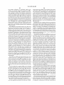
initialize
QQQ
sdait U! (or cellular
my
£5
yes
V
adapt u: {at LAN
adapt UI for mine
MW
cellar/LAN
in
5%!
US 8,509,186 B2
Page 2
(56)
References Cited
US. PATENT DOCUMENTS
2004/0087307 A1 *
2004/0266426 A1,.
5/2004 1b
t 1‘ “““““““““““ H 455/436
12/2004 Mirzhaet 31‘ “““““““ n 455/4262
retrieved
from
http://www.teleware.com/PDF/PMN-FMIi
wp060903.pdf, accessed Apr. 27, 2010.
Image of GUI on iPhone showing options for calling, http://cdn.
content.compendiumblog.com/uploads/user/19dc41fd-9692-444d
81ee-e9a49e34471a/88f333a7-94e6-4fe8-8257-e2655134a168/Im
2005/0170854 A1
8/2005 Benco et 31‘
2005/0190747 A1 *
9/2005
2006/0121916 A1
6/2006 Aborn et al.
2006/0159109 A1 *
7/2006 Lamkin et al. .............. .. 370/401
datasheet,
2007/0129103 A1
2007/0206569 A1
2007/0206580 A1
6/2007 Al-Shaikh
9/2007 Silver et al.
9/2007 Silver et al.
UCiDatasheetpdf, accessed Apr. 27, 2010.
Sindhwani et a1. ......... .. 370/352
2007/0268858 A1*
11/2007
Soto ............................ .. 370/328
2007/0281682 A1
12/2007 Raju et al.
2008/0113683 A1*
5/2008
2008/0130554
2009/0113460
2009/0258668
2009/0279683
2010/0009674
6/2008 Gisby et al.
A1
A1
A1
A1
A1
Paas et al. ................ .. 455/552.1
age/5a79a047453726ec5bf8a6628f37d112jpg, accessed Nov. 8,
2010
DiVitas Networks, DiVitas Mobile Uni?ed Communications
2010,
http://www.divitas.com/pdfs/DiVitasiMobilei
D2 Technologies, Inc., mCUE mobile convergence software solu
tion, 2007, http://www.d2tech.com/1-products/mcue.htm, accessed
Nov. 8, 2010.
OnRelay, Inc., “Uni?ed MBX Product Sheet”, 2010, retrieved from
http://www.onrelay.com/index.php?id:199 (download link on this
4/2009 Parrish et al.
10/2009 Kumar et al.
page), accessed Apr. 27, 2010.
11/2009 Gisby et al.
1/2010 Sapkota et al.
EP10170746.1.
OTHER PUBLICATIONS
Private Mobile Networks Ltd, “Fixed Mobile Integration: Realising
the potential of Private GSM Networks”, White Paper, 2006,
Extended European Search Report dated Nov. 11, 2010 from
Biggs, J .: “Skype for iPhone of?cially of?cial [Update]”, Internet
Citation, Mar. 30, 2009, p. 1, XP007915606, retrieved from the
Internet on Nov. 4, 2010 (http://www.crunchgear.com/2009/03/30/
skype-for-iphone-of?cially-of?cial).
* cited by examiner
US. Patent
Aug. 13, 2013
SSMXRWM
interface 33g
S'WRUM m
{3 era?n
Sheet 1 0110
.
system 35$
Dismay 11%
US 8,509,186 B2
Battery
interface 3,32
“HP
8'3th m
m» Auxiiiary :10 112,
Programs m
Massage
wash
Appiication
mama“? m
'
Main
DEWCQ Séate
0
Data Port 113
<~I~
Keybsard 115:1
4+»
Speaker 11%
Pmmssor
MOW“? liq
RAM 1%
+1»-
mg
PIM 1%;
Decoder 1%
4—!»
‘
10> Mmrophane ng
Connect
Maduis m
Cammunicatian
3T Policy
,
Subsystem 1%
Module 1515
I I
f
""
¢
Rem“?an lgé
t
Short~Range
,-'
WLAN Communicaticn
Gammunicatians
Subsystem 1&5
Egg
I",5 Network
ZQQ
3:},¢:::‘;j:"b
A
'
1‘
{Ether Device
Subsystems 32$
US. Patent
Aug. 13, 2013
Sheet 2 0f 10
US 8,509,186 B2
I
|
I
1 54
I
I
Signals
Reseéwr 3Q...
WW
ConImI
:
DSP 352
I
‘
I
l
I
.
I
L08 m
i 102
I
‘I
‘
| 156
I
I
I
,
Transmitter
1-5-2-
I
st.Ignais
W
Control
M
I
'I
I
I
I
I
US. Patent
Aug. 13, 2013
Sheet 3 0f 10
US 8,509,186 B2
I
I
I
I
i
Network
VLR
2152
I
I
I
I
(PSTN)
W MSCQLQ
222
I
I
I
l
I
,
was» ggq
HLR
*2.
‘2“"2
i
ass 2%
I
I
I
:
assm m
PCU
sssw m
m
I
I
I
I__
~~-~~_““~~~~_w~~~~~~_
Pubiic or
Host Systam
Private Netwark 233
ggg
FIG. 3
US. Patent
235&%3
gm
Aug. 13, 2013
US 8,509,186 B2
Sheet 4 0f 10
“8F2E%
.UEv
WNN
H
0
0
0
h56%“,2a@s8“a9:wm
mat $“ENmwM
mum?Namsw
“£91am g 5m2um%
US. Patent
- 2246mm
Aug. 13, 2013
EDGE? 13m)
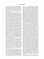
Manage Connections
‘ Tum A1; Connectinns Off
US 8,509,186 B2
Sheet 5 0f 10
2:40PM
EDGE? til"
Serw‘ces Status
\ integrated Mebiie voice
$tam's: avaitame
Connection: Mobiie Network
Mamie
Status: avaiiable
Set
Services
Up Biuetmm
Siatus
V
Wm
Mamie Newark Optimst
Biuetaeth Gptians
Wz~f=i Gptiam
6m
\ intemet Smice
Comedian: W;~Fi Newark
£n-teq2rise Server
~
Connection: Mobiie Network
Mobile Netwsrk: EDGE
Mamie Network Service: i?DGEi
W??? Netwu'rk: wafkwwfan
"0 FIG. 6B
US. Patent
Aug. 13, 2013
Sheet 6 0f 10
US 8,509,186 B2
MA
2 map-M
was? :1!“
560
Mob?a Netwcrk Options
/
Data Services On!fo
/
2:40;»
sane? it!"
670\
Piace (Ian
680\
My ceii number: 64? 555 @234 z
‘
“"532"E3?“€'2'§"5"§5§ ““““““““ “
Mobiie Network: *iEOGEW
(ff
‘ ___________________________________________________________ d"
E Aumma?? U manila!
maka a can
m
110
FIG. 6C
10°
100 110 FIG. 6D
, 710
2:4.6m
WiFI Y at?“
740
‘ Ezé?m
Manage Connections
Services Status mm
Tum At! Connections (1%
\thagraied Mabiia Vuice
W822
{3 giuetoum WW
{‘3 W$W
642
\\
Siaius: ava?ame
Connecticn: WFFE wauriq
744 \\
Mmai Service
Connection: N~Fi Network
m
624
Services Status
Set UQ Eiuaiooth
war: Y Mil
‘Enierprise Server.
w
8¥uetcoth Optiw
Wth' Optionwm
Connectiun: Wi‘Fi Network
/ W-Fi Network: wcrkmwian
'
m
“0 FIG.7A
100
mo
11OFIG. 7B
US. Patent
Aug. 13, 2013
Sheet 7 0f 10
' 221mm
wm vi? ml}
Mobiie Netwurk Options
US 8,509,186 B2
v mam
780
wm Y mi]
Mace Cali
Data Services Qni??
~~~~~~~~~~~~~~~~~~~~~~~~~~~~~~~~~~~~~~~~~ u
662
Network Ssiection Mode;
@ Aummat‘g *3 mama!
Type a name or numbar to
make a sail,
2:40PM
?mm?
T}
-
‘
_
Maii Cantacts
Cat
\‘
qr-
930
-
w"
N
m
-
,
_
Ca£
,
Cats:
‘ ark C?mera 586mg.
\
.I
'
Max! Cuntacts
Bszer Mimwk S ‘
'
mil
E?Mm
‘-
Cats:
wan
,1"
920
“910
m
Camera Seamh
OK;
110
FIG 9A
100
110
FIG. 9B
“30
US. Patent
activated
Aug. 13, 2013
'
CDMA device?
iii}.
yes
Sheet 8 0f 10
connectivity {ag
VWFi on board’?
yes
yes
3'
!
adapt U2 for LAN
QM};
adapt Ui for Mmiins
ceiiutarfLAN
~83);
i352
FIG. 8
US 8,509,186 B2
nea-
adapt UI for celiu?ar
oniy
5&5
US. Patent
Aug. 13, 2013
Sheet 9 0f 10
US 8,509,186 B2
pmvisianed far
W»Fi cniy
3 180
initi aiiza
&
m
detect fess of
cunnectivity
$
1 #95
review W poticy
‘
39:25
inactwate menu
op?nns
1 3 3i}
ceiiutar
VL
sewke
_
‘
yes
inactivated?
"0
regam signal
l
161g
1
1115
adapt U? fer onwiina
adapt U! for two-tine
16%
18 i3
L
reini?aiéze and
repmvision
FIG. 10
1 120
FIG. 11
US. Patent
Aug. 13, 2013
Sheet 10 0f 10
US 8,509,186 B2
prcvis§anad far
duaivmoda
i233
'prnvisianed '
{or igiigar'1‘
yes
i
W
no
l
aa‘apt UE for two~Iine
retain U!
w 15
w
provisicnecf far
duai-mcde
1300
¢
detact iass of
FIG. 12
ceituiar cannectivity
mi
4
adapt U? for Wi~Fi
aniy
1330
$
atter defauit codecs
far W1~Fi
3.525
FIG. 13
US 8,509,186 B2
1
2
CONVERSION OF MOBILE DEVICE TO
LAN-ONLY TELEPHONY FUNCTIONS
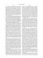
FIG. 13 is a ?owchart illustrating a method for adapting the
default codecs at the mobile device.
REFERENCE TO PRIOR APPLICATIONS
DETAILED DESCRIPTION
This application claims priority from US. Application No.
61/328,097, ?led Apr. 26, 2010.
The embodiments described herein provide a system,
method, and a mobile device for providing for a convergence
of ?xed and mobile voice communications in an enterprise
environment, while providing a dynamically adjusting user
BACKGROUND
interface responsive to network conditions at the mobile
device. There is provided a mobile device con?gurable for
1. Technical Field
The present application relates generally to management of
communication over at least one cellular network and over at
enterprise telephony at a mobile device.
2. Description of the Related Art
Mobile communication devices, such as smartphones, may
be used to extend the ?exibility of ?xed telephone networks
least on local area network (LAN), the mobile device being
adapted for voice communication using at least one mobile
within an enterprise. For example, dual-mode smartphones
capable of operating over both cellular and IP-based networks
may be deployed in an enterprise communication network
equipped with a private branch exchange (PBX). The network
may then route incoming telephone calls to the smartphone,
and outbound calls from the smartphone may appear to the
recipient to originate from the user’s desk telephone con
nected to the PBX. The ?xed mobile convergence realized by
integrating mobile devices into the enterprise’ s PBX provides
for an improved user experience both for the mobile device
users and callers, since the system may extend desk phone
functionality, such as conference calling, to the mobile
device, and also because the mobile device user may appear to
be available and “in the o?ice” even when travelling.
telecommunications standard and at least one IP-based net
work, capable of implementing a method of determining
whether the mobile device is con?gured for communication
20
over a cellular network connection, determining whether the
mobile device is con?gured for communication over a LAN,
and in some embodiments a wireless LAN, and adapting a
user interface at the mobile device to re?ect voice communi
cation availability only over those connections for which the
mobile device is determined to be con?gured. In some
aspects, determining whether the mobile device is con?gured
25
for communication over the cellular network connection may
comprise at least one of determining whether a SIM or RUIM
card is present in the mobile device, determining whether the
mobile device is an activated CDMA device, or determining
whether cellular connectivity has been inactivated at the
30
mobile device. Determining whether the mobile device is
con?gured for LAN or wireless LAN communication may
Although voice calls made using dual-mode smartphones
are typically connected over a cellular network, voice calls
comprise determining whether there is an appropriate com
may also be completed using Voice over IP (VoIP) protocols
munications subsystem on board.
Thus, the user interface may therefore be adapted to re?ect
voice communication availability only over the LAN connec
tion when the mobile device is determined not to be con?g
ured for communication over the cellular network but con?g
over an IP-based network. Thus, for example, if a wireless
LAN (LAN) connection is available to the smartphone, tele
35
phone calls may be routed over the LAN.
ured for LAN connectivity; voice communication availability
BRIEF DESCRIPTION OF THE DRAWINGS
In drawings which illustrate by way of example only
embodiments of the present application,
40
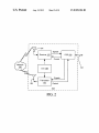
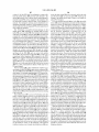
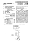
FIG. 1 is a block diagram of an embodiment of a mobile
device.
In these embodiments, availability of voice communica
FIG. 2 is a block diagram of an embodiment of a commu
nication subsystem component of the mobile device of FIG.
45
1.
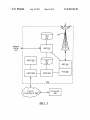
FIG. 3 is an exemplary block diagram of a node of a
wireless network for use with the mobile device of FIG. 1.
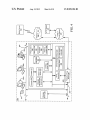
FIG. 4 is a block diagram illustrating components of a host
system in one exemplary con?guration for use with the wire
less network of FIG. 3 and the mobile device of FIG. 1.
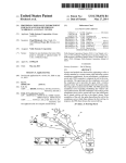
FIG. 5 is a schematic diagram of a network topology foruse
with the mobile device of FIG. 1.
50
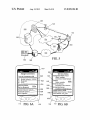
FIGS. 6A through 6D are schematic diagrams of graphical
user interfaces for the mobile device of FIG. 1.
only over the cellular network connection when the mobile
device is determined to be con?gured for such communica
tion, but not for communication over the LAN; or if both
forms of connectivity are available, the user interface may
re?ect the availability of voice communication over both.
55
tion over one or the other path may be indicated by displaying
service entry points in the user interface for those available
connections, or by displaying a telephone number only for
those connections for which the mobile device is con?gured.
In a further aspect of these embodiments, the mobile device
may be initially con?gured for voice communication over the
cellular network connection and the LAN connection, but
upon detection of a loss of cellular network connectivity, the
mobile device may adapt the user interface to re?ect voice
communication availability only over the LAN connection. In
still a further aspect, the mobib device may be adapted to use
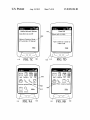
FIGS. 7A through 7D are further diagrams of graphical
one set of codecs for voice communication over the cellular
user interfaces for the mobile device of FIG. 1.
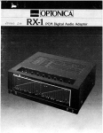
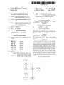
FIG. 8 is a ?owchart for a method of adapting the user
interface of the mobile device.
FIGS. 9A and 9B are further examples of graphical user
interfaces for the mobile device.
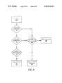
FIG. 10 is a ?owchart illustrating a further method for
adapting the user interface of the mobile device.
FIG. 11 is a ?owchart illustrating a method for handling a
network, and may then select a second set of codecs for voice
communication over the LAN connection upon detecting the
detected loss of connectivity.
FIG. 12 is a ?owchart illustrating a further method for
adapting the user interface of the mobile device.
60
loss of cellular network connectivity. In yet a further aspect,
the mobile device may be con?gured to place and receive
voice calls via a PBX over either the cellular network, the
LAN connection, or both.
These embodiments will be described primarily in relation
to a mobile wireless communication device such as a smart
65
phone, hereafter referred to as a mobile device. It will be
appreciated by those skilled in the art, however, that this
description is not intended to limit the scope of the described
US 8,509,186 B2
3
4
embodiments to smartphones. The methods and systems
described herein may be applied to any appropriate commu
nication or data processing device, whether portable or not,
including without limitation cellular phones, smartphones,
centric networks include WiFi 802.11TM, MobitexTM and
DataTACTM network communication systems. Examples of
other voice-centric data networks include Personal Commu
nication Systems (PCS) networks like GSM and Time Divi
organizers, personal digital assistants, desktop computers,
sion Multiple Access (TDMA) systems. The mobile device
terminals, laptops, tablets, notebook computers and the like.
and 2. The communication device may communicate with
100 may be provided with additional communication sub
systems, such as the wireless LAN (WLAN) communication
subsystem 105 also shown in FIG. 1. The WLAN communi
cation subsystem may operate in accordance with a known
The embodiments described herein may be implemented
on a communication device such as that illustrated in FIGS. 1
other devices over a wireless communication system or enter
network protocol such as one or more of the 802.1 1TM family
prise system as illustrated in FIGS. 3 and 4. The communi
cation device 100 may be a mobile device with two-way
of standards developed by IEEE. The communication sub
system 105 may be separate from, or integrated with, the
communication and advanced data communication capabili
ties including the capability to communicate with other
communication subsystem 104 or with the short-range com
munications module 122. The main processor 102 also inter
mobile devices or computer systems through a network of
transceiver stations. The communication device 100 can also
Memory (RAM) 106, a ?ash memory 108, a display 110, an
acts with additional subsystems such as a Random Access
have voice communication capabilities.
auxiliary input/output (I/O) subsystem 112, a data port 114, a
keyboard 116, a speaker 118, a microphone 120, the short
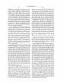
FIG. 1 is a block diagram of an exemplary embodiment of
a communication device 100. The communication device 100
includes a number of components such as a main processor 20
102 that controls the overall operation of the communication
device 100. Communication functions, including data and
voice communications, are performed through a communica
tion subsystem 104. Data received by the communication
device 100 can be decompressed and decrypted by decoder
103, operating according to any suitable decompression tech
perform communication-related functions, whereas other
sub systems can provide “resident” or on-device functions. By
way of example, the display 110 and the keyboard 116 can be
25
list.
A rendering circuit 125 is included in the device 100. When
various standards, such as Data Encryption Standard (DES),
Triple DES, or Advanced Encryption Standard (AES)).
a user speci?es that a data ?le is to be viewed on the display
30
110, the rendering circuit 125 analyzes and processes the data
?le for visualization on the display 110. Rendering circuit 125
may be implemented as hardware, software, or as a combi
nation of both hardware and software.
accordance with appropriate standards, such as J PEG, while
video data is typically compressed and decompressed in
accordance with appropriate standards, such as H.26x and
MPEG-x series standards.
The communication subsystem 104 receives messages
used for both communication-related functions, such as
entering a text message for transmission over the network
200, and device-resident functions such as a calculator or task
niques, and encryptioridecryption techniques according to
Image data is typically compressed and decompressed in
range communications 122 and other device subsystems 124.
Some of the subsystems of the communication device 100
The communication device 100 can send and receive com
35
munication signals over the wireless network 200 after
from and sends messages to a wireless network 200. In this
required network registration or activation procedures have
exemplary embodiment of the communication device 100,
the communication subsystem 104 is con?gured in accor
been completed. Network access is associated with a sub
scriber or user of the communication device 100. To identify
a subscriber, the communication device 100 requires a SIM/
RUIM card 126 (i.e. Subscriber Identity Module or a Remov
dance with one or more of Global System for Mobile Com
munication (GSM), General Packet Radio Services (GPRS)
standards, Enhanced Data GSM Environment (EDGE) and
Universal Mobile Telecommunications Service (UMTS).
New standards are still being de?ned, but it is believed that
they will have similarities to the network behavior described
herein, and it will also be understood by persons skilled in the
40
able User Identity Module) to be inserted into a SIM/RUIM
interface 128 in order to communicate with a network. The
SIM/RUIM card 126 is one type of a conventional “smart
card” that can be used to identify a subscriber of the commu
45
art that the embodiments described herein are intended to use
126, the communication device 100 is not fully operational
for communication with the wireless network 200. By insert
ing the SIM/RUIM card 126 into the SIM/RUIM interface
any other suitable standards that are developed in the future.
The wireless link connecting the communication subsystem
104 with the wireless network 200 represents one or more
different Radio Frequency (RF) channels, operating accord
50
ing to de?ned protocols speci?ed for GSM, GPRS, EDGE, or
UMTS, and optionally other network communications. With
voice mail, Short Message Service (SMS), and Multimedia
Messaging Services (MMS). More advanced services can
include: point of sale, ?eld service and sales force automa
55
communication device 100 in variant implementations. The
different types of wireless networks that can be employed
include, for example, data-centric wireless networks, voice
the SIM/RUIM card 126 can include some user parameters
60
such as an International Mobile Subscriber Identity (IMSI).
An advantage of using the SIM/RUIM card 126 is that a
subscriber is not necessarily bound by any single physical
physical base stations. Combined dual-mode networks
include, but are not limited to, Code Division MultipleAccess
(CDMA) or CDMA2000 networks, GSM/GPRS networks,
third-generation (3G) networks like EDGE, HSPA, HSPA+,
tion. The SIM/RUIM card 126 includes a processor and
memory for storing information. Once the SIM/RUIM card
126 is inserted into the SIM/RUIM interface 128, it is coupled
to the main processor 102. In order to identify the subscriber,
Other wireless networks can also be associated with the
centric wireless networks, and dual-mode networks that can
support both voice and data communications over the same
128, a subscriber can access all subscribed services. Services
can include: web browsing and messaging such as e-mail,
newer network protocols, these channels are capable of sup
porting both circuit switched voice communications and
packet switched data communications.
nication device 100 and to personalize the communication
device 100, among other things. Without the SIM/RUIM card
mobile device. The SIM/RUIM card 126 can store additional
subscriber information for a mobile device as well, including
65
datebook (or calendar) information and recent call informa
EVDO and UMTS, or fourth-generation (4G) networks such
tion. Alternatively, user identi?cation information can also be
as LTE and LTE Advanced. Some other examples of data
programmed into the ?ash memory 108.
US 8,509,186 B2
5
6
The communication device 100 may be a battery-powered
device including a battery interface 132 for receiving one or
Examples of a wireless infrastructure and an enterprise sys
tem are given in FIGS. 3 and 4, which are described in more
detail below.
The connect module 144 includes a set of Application
more rechargeable batteries 130. In at least some embodi
ments, the battery 130 can be a smart battery with an embed
ded microprocessor. The battery interface 132 is coupled to a
Programming Interfaces (APIs) that can be integrated with
regulator (not shown), which assists the battery 130 in pro
viding powerV+ to the communication device 100. Although
the communication device 100 to allow the communication
device 100 to use any number of services associated with the
enterprise system. The connect module 144 allows the com
current technology makes use of a battery, future technolo
gies such as micro fuel cells can provide the power to the
communication device 100.
The communication device 100 also includes an operating
system 134 and software components 136 to 146 which are
described in more detail below. The operating system 134 and
the software components 136 to 146 that are executed by the
main processor 102 are typically storod in a persistent store
such as the ?ash memory 108, which can alternatively be a
read-only memory (ROM) or similar storage element (not
shown). Those skilled in the art will appreciate that portions
of the operating system 134 and the software components 136
to 146, such as speci?c device applications, or parts thereof,
munication device 100 to establish an end-to-end secure,
authenticated communication pipe with the host system. A
subset of applications for which access is provided by the
connect module 144 can be used to pass IT policy commands
from the host system to the communication device 100. This
can be done in a wireless or wired manner.
These instructions can then be passed to the IT policy
module 146 to modify the con?guration of the device 100.
Alternatively, in some cases, the IT policy update can also be
done over a wired connection.
RAM 106. Other software components can also be included,
Other types of software applications can also be installed
on the communication device 100. These software applica
tions can be third party applications, which are added after the
manufacture of the communication device 100. Examples of
as is well known to those skilled in the art.
third party applications include games, calculators, utilities,
20
can be temporarily loaded into a volatile store such as the
The subset of software applications 136 that control basic
device operations, including data and voice communication
applications, will normally be installed on the communica
tion device 100 during its manufacture. Other software appli
etc.
25
network 200, the auxiliary 110 subsystem 112, the data port
114, the short-range communications subsystem 122, or any
other suitable device subsystem 124. This ?exibility in appli
cations include a message application 138 that can be any
suitable software program that allows a user of the commu
nication device 100 to send and receive electronic messages.
Various alternatives exist for the message application 138 as
The additional applications can be loaded onto the com
munication device 100 through at least one of the wireless
30
cation installation increases the functionality of the commu
nication device 100 and can provide enhanced on-device
is well known to those skilled in the art. Messages that have
functions, communication-related functions, or both. For
been sent or received by the user are typically stored in the
?ash memory 108 of the communication device 100 or some
electronic commerce functions and other such ?nancial trans
other suitable storage element in the communication device
example, secure communication applications can enable
35
actions to be performed using the communication device 100.
The data port 114 enables a subscriber to set preferences
through an external device or software application and
100. In at least some embodiments, some of the sent and
received messages can be stored remotely from the device
100 such as in a data store of an associated host system that the
extends the capabilities of the communication device 100 by
communication device 100 communicates with.
providing for information or software downloads to the com
munication device 100 other than through a wireless commu
The software applications can further include a device state
40
nication network. The alternate download path can, for
example, be used to load an encryption key onto the commu
nication device 100 through a direct and thus reliable and
module 140, a Personal Information Manager (PIM) 142, and
other suitable modules (not shown). The device state module
140 provides persistence, i.e. the device state module 140
ensures that important device data is stored in persistent
memory, such as the ?ash memory 108, so that the data is not
lost when the communication device 100 is turned off or loses
power.
45
The PIM 142 includes functionality for organiZing and
managing data items of interest to the user, such as, but not
limited to, e-mail, contacts, calendar events, voice mails,
appointments, and task items. A PIM application has the
ability to send and receive data items via the wireless network
200. PIM data items can be seamlessly integrated, synchro
nized, and updated via the wireless network 200 with the
mobile device subscriber’s corresponding data items stored
50
battery 130 of the communication device 100.
The short-range communications subsystem 122 provides
55
and/or associated with a host computer system. This func
tionality creates a mirrored host computer on the communi
cation device 100 with respect to such items. This can be
include an infrared device and associated circuits and com
range communication standards include standards developed
60
The communication device 100 also includes a connect
by the Infrared Data Association (IrDA), BluetoothTM, and
the 802.11TM family of standards.
In use, a received signal such as a text message, an e-mail
module 144, and an information technology (IT) policy mod
ule 146. The connect module 144 implements the communi
cation protocols that are required for the communication
device 100 to communicate with the wireless infrastructure
and any host system, such as an enterprise system, that the
communication device 100 is authorized to interface with.
for communication between the communication device 100
and different systems or devices, without the use of the wire
less network 200. For example, the subsystem 122 can
ponents for short-range communication. Examples of short
particularly advantageous when the host computer system is
the mobile device subscriber’s of?ce computer system.
trusted connection to provide secure device communication.
The data port 114 can be any suitable port that enables data
communication between the communication device 100 and
another computing device. The data port 114 can be a serial or
a parallel port. In some instances, the data port 114 can be a
USB port that includes data lines for data transfer and a
supply line that can provide a charging current to charge the
message, or web page download will be processed by the
communication subsystem 104 and input to the main proces
sor 102. The main processor 102 will then process the
65
received signal for output to the display 110 or alternatively to
the auxiliary I/O subsystem 112. A subscriber can also com
pose data items, such as e-mail messages, for example, using
US 8,509,186 B2
7
8
the keyboard 116 in conjunction with the display 110 and
possibly the auxiliary I/O subsystem 112. The auxiliary sub
shown in FIG. 1, may be provided with similar components as
those described above con?gured for communication over the
system 112 can include devices such as: a touchscreen,
appropriate frequencies and using the appropriate protocols.
mouse, track ball, infrared ?ngerprint detector, or a roller
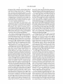
FIG. 3 is a block diagram of an exemplary implementation
of a node 202 of the wireless network 200. In practice, the
wheel with dynamic button pres sing capability. The keyboard
116 may be an alphanumeric keyboard and/or telephone-type
keypad. However, other types of keyboards can also be used.
wireless network 200 comprises one or more nodes 202. In
A composed item can be transmitted over the wireless net
tion device 100 can communicate with the node 202 within
work 200 through the communication subsystem 104. It will
be appreciated that if the display 110 comprises a touch
screen, then the auxiliary subsystem 112 may still comprise
the wireless network 200. In the exemplary implementation
of FIG. 3, the node 202 is con?gured in accordance with
General Packet Radio Service (GPRS) and Global Systems
for Mobile (GSM) technologies. The node 202 includes abase
conjunction with the connect module 144, the communica
one or more of the devices identi?ed above.
For voice communications, the overall operation of the
communication device 100 is substantially similar, except
that the received signals are output to the speaker 118, and
signals for transmission are generated by the microphone
station controller (BSC) 204 with an associated tower station
206, a Packet Control Unit (PCU) 208 added for GPRS sup
port in GSM, a Mobile Switching Center (MSC) 210, a Home
Location Register (HLR) 212, a Visitor Location Registry
(VLR) 214, a Serving GPRS Support Node (SGSN) 216, a
Gateway GPRS Support Node (GGSN) 218, and a Dynamic
120. Alternative voice or audio I/O subsystems, such as a
voice message recording subsystem, can also be implemented
Host Con?guration Protocol (DHCP) 220. This list of com
on the communication device 100. Although voice or audio
signal output is accomplished primarily through the speaker
20
118, the display 110 can also be used to provide additional
information such as the identity of a calling party, duration of
munications through the network 200.
a voice call, or other voice call related information.
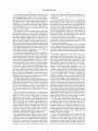
FIG. 2 shows an exemplary block diagram of the commu
nication subsystem component 104. The communication sub
ponents is not meant to be an exhaustive list of the compo
nents of every node 202 within a GSM/GPRS network, but
rather a list of components that are commonly used in com
In a GSM network, the MSC 210 is coupled to the BSC 204
25
and to a landline network, such as a Public Switched Tele
as associated components such as one or more embedded or
phone Network (PSTN) 222 to satisfy circuit switched
requirements. The connection through the PCU 208, the
internal antenna elements 154 and 156, Local Oscillators
(LOs) 158, and a processing module such as a Digital Signal
SGSN 216 and the GGSN 218 to a public or private network
(Internet) 224 (also referred to herein generally as a shared
system 104 includes a receiver 150, a transmitter 152, as well
Processor (DSP) 160. The particular design of the communi
cation subsystem 104 is dependent upon the communication
network 200 with which the communication device 100 is
intended to operate. Thus, it should be understood that the
design illustrated in FIG. 2 serves only as one example.
Signals received by the antenna 154 through the wireless
network 200 are input to the receiver 150, which can perform
such common receiver functions as signal ampli?cation, fre
30
capable mobile devices. In a GSM network extended with
GPRS capabilities, the BSC 204 also contains the Packet
Control Unit (PCU) 208 that connects to the SGSN 216 to
35
quency down conversion, ?ltering, channel selection, and
analog-to-digital (A/D) conversion. AID conversion of a
received signal allows more complex communication func
tions such as demodulation and decoding to be performed in
40
the DSP 160. In a similar manner, signals to be transmitted are
processed, including modulation and encoding, by the DSP
control segmentation, radio channel allocation and to satisfy
packet switched requirements. To track the location of the
communication device 100 and availability for both circuit
switched and packet switched management, the HLR 212 is
shared between the MSC 210 and the SGSN 216. Access to
the VLR 214 is controlled by the MSC 210.
The station 206 is a ?xed transceiver station and together
with the BSC 204 form ?xed transceiver equipment. The
?xed transceiver equipment provides wireless network cov
erage for a particular coverage area commonly referred to as
a “cell”. The ?xed transceiver equipment transmits commu
160. These DSP-processed signals are input to the transmitter
152 for digital-to-analog (D/A) conversion, frequency up
network infrastructure) represents the data path for GPRS
45
nication signals to and receives communication signals from
conversion, ?ltering, ampli?cation and transmission over the
mobile devices within its cell via the station 206. The ?xed
wireless network 200 via the antenna 156. The DSP 160 not
transceiver equipment normally performs such functions as
only processes communication signals, but also provides for
receiver and transmitter control. For example, the gains
applied to communication signals in the receiver 150 and the
modulation and possibly encoding and/or encryption of sig
nals to be transmitted to the communication device 100 in
50
accordance with particular, usually predetermined, commu
transmitter 152 can be adaptively controlled through auto
nication protocols and parameters, under control of its con
matic gain control algorithms implemented in the DSP 160.
troller. The ?xed transceiver equipment similarly demodu
lates and possibly decodes and decrypts, if necessary, any
communication signals received from the communication
device 100 within its cell. Communication protocols and
The wireless link between the communication device 100
and the wireless network 200 can contain one or more differ
ent channels, typically different RF channels, and associated
protocols used between the communication device 100 and
55
parameters can vary between different nodes. For example,
the wireless network 200. An RF channel is a limited resource
one node can employ a different modulation scheme and
that should be conserved, typically due to limits in overall
bandwidth and limited battery power of the communication
device 100. When the communication device 100 is fully
operational, the transmitter 152 is typically keyed or turned
on only when it is transmitting to the wireless network 200
operate at different frequencies than other nodes.
60
pro?le is stored in the HLR 212. The HLR 212 also contains
location information for each registered mobile device and
and is otherwise turned off to conserve resources. Similarly,
the receiver 150 is periodically turned off to conserve power
until it is needed to receive signals or information (if at all)
during designated time periods. Other communication sub
systems, such as the WLAN communication subsystem 105
For all communication devices 100 registered with a spe
ci?c network, permanent con?guration data such as a user
can be queried to determine the current location of a mobile
65
device. The MSC 210 is responsible for a group of location
areas and stores the data of the mobile devices currently in its
area of responsibility in the VLR 214. Further, the VLR 214
also contains information on mobile devices that are visiting
US 8,509,186 B2
10
other networks. The information in the VLR 214 includes part
of the permanent mobile device data transmitted from the
HLR 212 to the VLR 214 for faster access. By moving addi
devices can communicate wirelessly with the host system 250
through one or more nodes 202 of the wireless network 200.
The host system 250 comprises a number of network com
ponents connected to each other by a network 260. For
instance, a user’s desktop computer 26211 with an accompa
nying cradle 264 for the user’s communication device 100 is
tional information from a remote HLR 212 node to the VLR
214, the amount of traf?c between these nodes canbe reduced
so that voice and data services can be provided with faster
situated on a LAN connection. The cradle 264 for the com
response times and at the same time requiring less use of
computing resources.
The SGSN 216 and the GGSN 218 are elements added for
munication device 100 can be coupled to the computer 26211
by a serial or a Universal Serial Bus (USB) connection, for
example. Other user computers 262b-262n are also situated
GPRS support; namely packet switched data support, within
on the network 260, and each can be equipped with an accom
GSM. The SGSN 216 and the MSC 210 have similar respon
panying cradle 264. The cradle 264 facilitates the loading of
sibilities within the wireless network 200 by keeping track of
information (e.g. PIM data, private symmetric encryption
the location of each communication device 100. The SGSN
216 also performs security functions and access control for
data traf?c on the wireless network 200. The GGSN 218
keys to facilitate secure communications) from the user com
puter 26211 to the communication device 100, and can be
particularly useful for bulk information updates often per
provides internetworking connections with external packet
switched networks and connects to one or more SGSNs 216
via an Internet Protocol (IP) backbone network operated
within the network 200. During normal operations, a given
20
communication device 100 must perform a “GPRS Attach” to
acquire an IP address and to access data services. This
requirement is not present in circuit switched voice channels
as Integrated Services Digital Network (ISDN) addresses are
used for routing incoming and outgoing calls. Currently, all
GPRS capable networks use private, dynamically assigned IP
addresses, thus requiring the DHCP server 220 connected to
the GGSN 218. There are many mechanisms for dynamic IP
assignment, including using a combination of a Remote
Authentication Dial-In User Service (RADIUS) server and a
DHCP server. Once the GPRS Attach is complete, a logical
connection is established from a communication device 100,
through the PCU 208, and the SGSN 216 to an Access Point
Node (APN) within the GGSN 218. The APN represents a
logical end of an IP tunnel that can either access direct Inter
net compatible services or private network connections. The
APN also represents a security mechanism for the network
200, insofar as each communication device 100 must be
explicitly shown in FIG. 4. Furthermore, only a subset of
25
network components of the host system 250 are shown in
FIG. 4 for ease of exposition, and it will be understood by
persons skilled in the art that the host system 250 will com
prise additional components that are not explicitly shown in
FIG. 4 for this exemplary con?guration. More generally, the
host system 250 can represent a smaller part of a larger
30
network (not shown) of the organization, and can comprise
different components and/or be arranged in different topolo
gies than that shown in the exemplary embodiment of FIG. 4.
To facilitate the operation of the communication device
100 and the wireless communication of messages and mes
35
assigned to one or more APNs and communication devices
100 cannot exchange data without ?rst performing a GPRS
formed in initializing the communication device 100 for use.
The information downloaded to the communication device
100 can include certi?cates used in the exchange of messages.
It will be understood by persons skilled in the art that the
user computers 262a-262n are typically also connected to
other peripheral devices, such as printers, etc., which are not
40
sage-related data between the communication device 100 and
components of the host system 250, a number of wireless
communication support components 270 can be provided. In
some implementations, the wireless communication support
components 270 can include a message management server
272, a mobile data server 274, a web server, such as Hypertext
Attach to an APN that it has been authorized to use. The APN
can be considered to be similar to an Internet domain name
Transfer Protocol (HTTP) server 275, a contact server 276,
such as “myconnection.wireless.com”.
Once the GPRS Attach operation is complete, a tunnel is
located outside the enterprise system, as indicated by the
created and all traf?c is exchanged within standard IP packets
using any protocol that can be supported in IP packets. This
and a device manager module 278. HTTP servers can also be
45
HTTP server 279 attached to the network 224. The device
manager module 278 includes an IT Policy editor 280 and an
IT user property editor 282, as well as other software com
includes tunneling methods such as IP over IP as in the case
ponents for allowing an IT administrator to con?gure the
with some IPSecurity (Ipsec) connections used with Virtual
communication devices 100. In an alternative embodiment,
there can be one editor that provides the functionality of both
the IT policy editor 280 and the IT user property editor 282.
The support components 270 also include a data store 284,
and an IT policy server 286. The IT policy server 286 includes
Private Networks (VPN). These tunnels are also referred to as
Packet Data Protocol (PDP) Contexts and there are a limited
number of these available in the network 200. To maximize
use of the PDP Contexts, the network 200 will run an idle
timer for each PDP Context to determine if there is a lack of
activity. When a communication device 100 is not using its
PDP Context, the PDP Context can be de-allocated and the IP
50
a processor 288, a network interface 290 and a memory unit
292. The processor 288 controls the operation of the IT policy
55
server 286 and executes functions related to the standardized
60
IT policy as described below. The network interface 290
allows the IT policy server 286 to communicate with the
various components of the host system 250 and the commu
nication devices 100. The memory unit 292 can store func
tions used in implementing the IT policy as well as related
data. Those skilled in the art know how to implement these
various components. Other components can also be included
as is well known to those skilled in the art. Further, in some
implementations, the data store 284 can be part of any one of
address returned to the IP address pool managed by the DI
ICP server 220.
FIG. 4 is a block diagram illustrating components of an
exemplary con?guration of a host system 250 with which the
communication device 100 can communicate in conjunction
with the connect module 144. The host system 250 will typi
cally be a corporate enterprise or other local area network
(LAN), but can also be a home of?ce computer or some other
private system, for example, in variant implementations. In
the example shown in FIG. 4, the host system 250 is depicted
as a LAN of an organization to which a user of the commu
nication device 100 belongs. Typically, a plurality of mobile
65 the servers.
In this exemplary embodiment, the communication device
100 communicates with the host system 250 through node
US 8,509,l86 B2
11
12
202 of the wireless network 200 and a shared network infra
structure 224 such as a service provider network or the public
Internet. Access to the host system 250 can be provided
through one or more routers (not shown), and computing
devices of the host system 250 can operate from behind a
device 100. Alternatively, the data store associated with the
message server 268 can store all of the messages for the user
of the communication device 100 and only a smaller number
of messages can be stored on the communication device 100
to conserve memory. For instance, the most recent messages
?rewall or proxy server 266. The proxy server 266 provides a
(i.e. those received in the past two to three months for
secure node and a wireless intemet gateway for the host
system 250. The proxy server 266 intelligently routes data to
the correct destination server within the host system 250.
In some implementations, the host system 250 can include
example) can be stored on the communication device 100.
When operating the communication device 100, the user
may wish to have e-mail mes sages retrieved for delivery to the
communication device 100. The message application 138
operating on the communication device 100 can also request
messages associated with the user’s account from the mes
sage server 268. The message application 138 can be con?g
a wireless VPN router (not shown) to facilitate data exchange
between the host system 250 and the communication device
100. The wireless VPN router allows a VPN connection to be
established directly through a speci?c wireless network to the
ured (either by the user or by an administrator, possibly in
accordance with an organization’s IT policy) to make this
communication device 100. The wireless VPN router can be
used with the Internet Protocol (IP) Version 6 (IPV6) and
IP-based wireless networks. This protocol can provide
enough IP addresses so that each mobile device has a dedi
cated IP address, making it possible to push information to a
mobile device at any time. An advantage of using a wireless
20
VPN router is that it can be an off-the-shelfVPN component,
and does not require a separate wireless gateway and separate
wireless infrastructure. A VPN connection may be a Trans
The message management server 272 can be used to spe
ci?cally provide support for the management of messages,
mission Control Protocol (TCP)/IP or User Datagram Proto
col (UDP)/IP connection for delivering the messages directly
25
to the communication device 100 in this alternative imple
mentation.
Messages intended for a user of the communication device
100 are initially received by a message server 268 of the host
system 250. Such messages can originate from any number of
request at the direction of the user, at some pre-de?ned time
interval, or upon the occurrence of some pre-de?ned event. In
some implementations, the communication device 100 is
assigned its own e-mail address, and messages addressed
speci?cally to the communication device 100 are automati
cally redirected to the communication device 100 as they are
received by the message server 268.
30
such as e-mail messages, that are to be handled by mobile
devices. Generally, while messages are still stored on the
message server 268, the message management server 272 can
be used to control when, if, and how messages are sent to the
communication device 100. The message management server
272 also facilitates the handling of messages composed on the
sources. For instance, a message can have been sent by a
communication device 100, which are sent to the message
sender from the computer 262b within the host system 250,
server 268 for subsequent delivery.
from a different mobile device (not shown) connected to the
For example, the message management server 272 can
monitor the user’s “mailbox” (e.g. the message store associ
wireless network 200 or a different wireless network, or from
a different computing device, or other device capable of send
ing messages, via the shared network infrastructure 224, pos
sibly through an application service provider (ASP) or Inter
35
net service provider (ISP), for example.
The message server 268 typically acts as the primary inter
face for the exchange of messages, particularly e-mail mes
sages, within the organization and over the shared network
infrastructure 224. Each user in the organization that has been
set up to send and receive messages is typically associated
ment server 272 can also, through an encoder (not shown)
40
with a user account managed by the message server 268.
Some exemplary implementations of the message server 268
45
on the communication device 100 (e.g. encrypted using
mentations, the host system 250 can comprise multiple mes
50
Triple DES), decrypt and decompress the composed mes
55
sages, re-format the composed messages if desired so that
they will appear to have originated from the user’ s computer
262a, and re-route the composed messages to the message
server 268 for delivery.
Certain properties or restrictions associated with messages
to provide additional functions beyond message manage
ment, including the management of data associated with cal
endars and task lists, for example.
When messages are received by the message server 268,
they are typically stored in a data store associated with the
that are to be sent from and/or received by the communication
device 100 can be de?ned (e.g. by an administrator in accor
message server 268. In at least some embodiments, the data
store can be a separate hardware unit, such as data store 284,
with which the message server 268 communicates. Messages
can be subsequently retrieved and delivered to users by
accessing the message server 268. For instance, an e-mail
client application operating on a user’s computer 262a can
request the e-mail messages associated with that user’s
dance with IT policy) and enforced by the message manage
ment server 272. These may include whether the communi
60
each message that is locally stored on the communication
cation device 100 can receive encrypted and/or signed
messages, minimum encryption key sizes, whether outgoing
messages must be encrypted and/or signed, and whether cop
ies of all secure messages sent from the communication
device 100 are to be sent to a pre-de?ned copy address, for
account stored on the data store associated with the message
server 268. These messages are then retrieved from the data
store and stored locally on the computer 26211. The data store
associated with the message server 268 can store copies of
associated therewith, compress message data, using any suit
able compression/decompression technology (e.g. YK com
pression, JPEG, MPEG-x, H.26x, and other known tech
niques) and encrypt messages (e. g. using an encryption
technique such as Data Encryption Standard (DES), Triple
DES, or Advanced Encryption Standard (AES)), and push
them to the communication device 1 00 via the shared network
infrastructure 224 and the wireless network 200. The message
management server 27 2 can also receive messages composed
include a Microsoft ExchangeTM server, a Lotus DominoTM
server, a Novell GroupwiseTM server, or another suitable mail
server installed in a corporate environment. In some imple
sage servers 268. The message server 268 can also be adapted
ated with the user’s account on the message server 268) for
new e-mail messages, and apply user-de?nable ?lters to new
messages to determine if and how the messages are relayed to
the user’s communication device 100. The message manage
65
example.
The message management server 272 can also be adapted
to provide other control functions, such as only pushing cer
US 8,509,186 B2
13
14
tain message information or pre-de?ned portions (e.g.
istrator interacts to con?gure various settings for the commu
nication devices 100. As mentioned, the IT administrator can
use lT policy rules to de?ne behaviors of certain applications
“blocks”) of a message stored on the message server 268 to
the communication device 100. For example, in some cases,
when a message is initially retrieved by the communication
on the communication device 100 that are permitted such as
device 100 from the message server 268, the message man
agement server 272 can push only the ?rst part of a message
phone, web browser or Instant Messenger use. The IT policy
rules can also be used to set speci?c values for con?guration
settings that an organization requires on the communication
devices 100 such as auto signature text, WLAN/VolP/VPN
to the communication device 100, with the part being of a
pre-de?ned size (e.g. 2 KB). The user can then request that
more of the message be delivered in similar-sized blocks by
con?guration, security requirements (e.g. encryption algo
the message management server 272 to the communication
rithms, password rules, etc.), specifying themes or applica
device 100, possibly up to a maximum pre-de?ned message
size. Accordingly, the message management server 272
tions that are allowed to run on the communication device
100, and the like.
Rendering data ?les originally optimized or prepared for
facilitates better control over the type of data and the amount
of data that is communicated to the communication device
100, and can help to minimize potential waste of bandwidth
visualization on large-screen displays on a portable electronic
device display often requires additional processing prior to
The mobile data server 274 encompasses any other server
visualization on the small-screen portable electronic device
displays. According to an embodiment, this additional pro
that stores information that is relevant to the corporation. The
cessing is accomplished by the rendering engine 125 shown
or other resources.
in FIG. 1. As will be appreciated by those of skill in the art, the
mobile data server 274 can include, but is not limited to,
databases, online data document repositories, customer rela
tionship management (CRM) systems, or enterprise resource
planning (ERP) applications. The mobile data server 274 can
also connect to the lntemet or other public network, through
20
rendering engine can be implemented in hardware, software,
25
or a combination thereof, and can comprise a dedicated image
processor and associated circuitry, or can be implemented
within main processor 102.
As noted above, the mobile device 100 may be a dual-mode
or multiple-mode device that is con?gured to operate in not
HTTP server 275 or other suitable web server such as an File
Transfer Protocol (FTP) server, to retrieve HTTP webpages
and other data. Requests for webpages are typically routed
only voice-centric, but also data-centric networks. For
example, the mobile device may be con?gured to communi
through mobile data server 274 and then to HTTP server 275,
through suitable ?rewalls and other protective mechanisms.
cate over a dual-mode network such as those identi?ed above,
The web server then retrieves the webpage over the lntemet,
and returns it to mobile data server 274. As described above in
relation to message management server 272, mobile data
server 274 is typically provided, or associated, with an
encoder 277 that permits retrieved data, such as retrieved
including but not limited to CDMA, CDMA2000, GSM/
webpages, to be decompressed and compressed, using any
suitable compression technology (e. g. YK compression,
JPEG, MPEG-x, H.26x and other known techniques), and
encrypted (e.g. using an encryption technique such as DES,
30
GPRS, EDGE, EVDO, HSPA, HSPA+, UMTS, and LTE, and
may also be con?gured to communicate over wireless net
35
works that are typically lP-based, such as wireless LANs
implementing the Wi-Fi protocol (one or more of the lEEE
802.11 suite of protocols), personal area networks imple
menting other protocols such as Bluetooth, other wireless
networks implementing wireless broadband standards such
as WiMAX (one or more of the lEEE 802.16 suite of proto
Triple DES, or AES), and then pushed to the communication
cols), and the like. The mobile device may also be con?gured
device 100 via the shared network infrastructure 224 and the
wireless network 200. While encoder 277 is only shown for
mobile data server 274, it will be appreciated that each of
message server 268, message management server 272, and
to operate over a ?xed connection to an lP-based network, for
40 example via a USB or Ethernet connection. For ease of ref
erence, these two modes are respectively referred to generally
as cellular and LAN modes or networks, where LAN includes
both wireless and wired LANs. Although the description
HTTP servers 275 and 279 can also have an encoder associ
ated therewith.
The contact server 276 can provide information for a list of
contacts for the user in a similar fashion as the address book
herein is generally directed to an implementation on a mobile
45
on the communication device 100. Accordingly, for a given
contact, the contact server 276 can include the name, phone
number, work address and e-mail address of the contact,
among other information. The contact server 276 can also 50
provide a global address list that contains the contact infor
mation for all of the contacts associated with the host system
250.
It will be understood by persons skilled in the art that the
message management server 272, the mobile data server 274,
communication device typically communicating over net
works over a wireless link, it will be understood by those
skilled in the art that the description is not intended to be so
limiting, and includes wired connections. The mobile device
100 may therefore be equipped with multiple interfaces and
transceivers for communicating over different ?xed and wire
less networks, and may be con?gured to communicate over
more than one network at a given time.
Further, the mobile device 100 may capable of operating in
55
the HTTP server 275, the contact server 276, the device
a single-line mode and in a multi-line mode. Thus, inbound
calls to a plurality of telephone numbers associated with the
device 100 may be received at the device 100 when in multi
server 272 can be integrated with the message server 268, or
line mode; and when the device 100 is in the multi-line mode,
outbound calls may be placed at the device 100 using a
selected one of the telephone numbers associated with the
device, so that caller identi?cation delivered to the recipient
of the outbound call will identify the call as being placed
some other server in the host system 250. Alternatively, the
using that selected telephone number.
host system 250 can comprise multiple message management
servers 272, particularly in variant implementations where a
large number of mobile devices need to be supported.
Some inbound and outbound calls may be handled through
a private branch exchange (PBX) in the same enterprise net
manager module 278, the data store 284 and the IT policy
server 286 do not need to be implemented on separate physi
cal servers within the host system 250. For example, some or
all of the functions associated with the message management
The device manager module 278 provides an IT adminis
trator with a graphical user interface with which the IT admin
60
65
work environment as the mobile device 100, for example a
PBX associated with the ho st system 250. If the mobile device
is con?gured to communicate with the host system 250 over
US 8,509,186 B2
15
16
at least a LAN, the PBX may be con?gured to connect calls
from the mobile device 100 and route calls directed to the
device 100 over the LAN. Calls may also be routed through a
access the host system 250 over a network, such as the wide
remotely hosted PBX service assigned to the enterprise, but
not necessarily forming a physical part of the enterprise’s
private Wi-Fi hotspot.
network. The enterprise’s systems may be distributed over
device 100 may be registered or activated with the respective
signi?cant geographic distances. Hosted telephony services
network. A process for identifying a subscriber to a cellular
may be used to provide an integrated PBX environment for all
users within the enterprise.
FIG. 5 illustrates a possible network topology for the
network using a SIM card 126 is described above. Other
methods of registering or identifying the mobile device 100 to
various networks will be known to those of ordinary skill in
the art. However, registration or activation may not be
required for all wireless networks 200, LANs 520 or other
area IP network 224, via an access point 530, which may be
located at the mobile device user’s home, or at a public or
For some wireless networks 200 or LANs 520, the mobile
mobile device 100, including two possible paths for data
traf?c 510 and voice traf?c 560. The enterprise environment
of the host system 250 may include a PBX 580, provided with
access units 530, as some networks may allow access without
connectivity to the public switched telephone network (rep
prior registration or activation. The mobile device 100 may
resented in FIG. 5 by the telephone network cloud 570) over
a PRI (primary rate interface) connection. The PBX 580 may
also be provisioned or con?gured to access the wireless net
work 200 or LAN 520 or other access point 530. Methods of
provisioning services on a mobile device 100 will be gener
be a conventional legacy PBX (i.e., a TDM or time division
multiplexing PBX) or an IP PBX based on an IP architecture,
or combination thereof. As noted above, the PBX may be a
remotely hosted service. Voice communication between the
ally known to those skilled in the art, but as a non-limiting
example, a request for registration may be sent from the
20
mobile device 100 to a registration server of a service (not
mobile device 100 and the PBX 580 may therefore be routed
shown). If the request is approved, the registration server may
through the wireless network 200, through the public
transmit to the mobile device 100 a service book containing
data and instructions to enable the mobile device 100 to
switched telephone network 570 and wide area network 224,
and thence to the PBX 580, and vice versa. Each mobile
device 100 to be connected with the PBX 580, as well as any
conventional of?ce telephones 590 connected to the PBX
25
user to enter account information relevant to the associated
service. This information is then transmitted from the mobile
device 100 to a provisioning server of the service provider
(not shown), which may then create a service account asso
580, may be assigned a DID (direct inward dial) or extension
number. In addition, as described previously the mobile
device 100 may also communicate via the wireless network
200 and over a wide area network 224 with the host system
250 over a data communication channel, which may be an
30
IP-based channel.
The host system 250 in this embodiment comprises or is
associated with the PBX 580 through a server or gateway 550.
The server 550 and the PBX 580 may communicate over an IP
35
data channel, for example implementing a SIP (session ini
and the server 550 may convert TDM data received from the
PBX 580 to IP data. After receiving voice call data from the
PBX 580, the server 550 provides the data in a VoIP-compli
ant format to other components of the host system 250 for
re-routing to the mobile device 100 over the data communi
cation channel 510. Thus, calls to or from the mobile device
40
100 may be routed over an IP network to the PBX 580,
45
allowing the host system 250 to handle authentication of the
mobile device 100 and other administrative functions relating
device 100 may be restricted to permit communication over
the access point 530 as well in this instance. These additional
50
wireless network 200, which as described above may com
prise one or more nodes 202 con?gured for communication in
checked to determine whether the mobile device 100 is per
55
60
through the LAN 520. This network con?guration thus pro
vides the user with a communication service handling both
(whether wireless or not). Instead, the mobile device 100 may
mitted to communicate using each provisioned service.
When the mobile device 100 is con?gured to handle both
?xed and mobile voice communications as described above,
the device 100 may consequently be converted from a single
line deviceia device associated with a single telephone
numberito a multiple-line device. The mobile device 100
may be registered with a cellular network service, but at the
same time it may be associated with a DID through the PBX
580. Therefore, the device 100 will be reachable through two
distinct telephone numbers, and each telephone number will
?xed and wireless voice calls. It will also be appreciated by
those skilled in the art that access to the host system 250 need
not be limited to access via the enterprise LAN network
settings may be stored in a branding or con?guration ?le
stored in the memory of the mobile device 100. When the
mobile device 100 is initialized, the settings, which may have
been established during the provisioning described above, are
LAN, represented by the access point 520. The mobile device
100 may therefore be able to handle calls routed through the
PBX 580 not only over the wireless network 200, but also
Mobile Alliance Ltd.
In addition to the provisioning with the service book, addi
tional settings may be established at the device 100 or pushed
to the device 100 concerning its access to the wireless net
work 200, LAN 520, or access point 530. For example, con
?guration settings may be established disabling one or more
modes of communication. If the con?guration settings are set
to disable cellular communications, the mobile device 100
may be restricted to communication over the LAN 520 only.
Such a setting may be desirable in an enterprise environment
where security or accounting concerns require that calls be
routed through the host system 250 for its authentication and
record-keeping functions, or where it is desirable to control
costs by disabling cellular communication. The mobile
to the voice call.
The mobile device 100’s access to IP networks and to the
accordance a suitable mobile telephony standard. In turn, the
wireless network 200 provides the mobile device 100 with
connectivity to the Internet or other public wide area network
224, and thence to the host system 250. At the same time, if
the mobile device 100 is a multiple-mode device, it may also
communicate with the host system 250 over an enterprise
ciated with the mobile device 100. Provisioning may also be
carried out in compliance with the OMA DM (Open Mobile
Alliance Device Management) speci?cation version 1.2 or its
predecessor or successor versions, published by the Open
tiation protocol) circuit. If the PBX 580 is a TDM PBX, then
the communication channel may be an ISDN PRI connection,
public switched telephone network is provided through the
provision the service. The service book, when received at the
mobile device 100, may be self-executing, and permits the
65
be routed to a different path. In other embodiments, it may be
possible to provision the device 100 with more than two
telephone numbers.