1
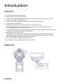
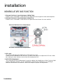
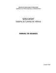
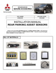
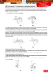
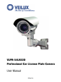
VLPR-54L922D Professional Car License Plate Camera User Manual Veilux Inc. safety information CAUTION 1. Never point the camera toward the sun Do not expose the lens directly to the sun or to strong light as this may damage the pick-up device. 2. Handle this camera with care Avoid any shock of the camera. Improper handing could damage the camera. 3. Requires a proper operating environment This camera is designed for both indoor and outdoor use. The allowable temperature range of operation of this camera is between -10°C~50°C and the allowable humidity is 80% maximum. 4. Clean the lens regularly It is recommended that the lens surface be cleaned regularly or when the lens is dusty to prevent obstruction of IR light. Cleaning should be done by using a chamois, a very fine soft cloth, lens tissue or cotton tipped applicator and ethanol to carefully remove any fingerprint of dust. 5. Check the power source voltage The power source voltage should be within the specified range. (Camera must meet the specification) 2 safety information content CONTENT INTRODUCTION Features Dimension 4 4 INSTALLATION Nomenclature and Function Installation Impor tant Notes 5 6 8 TECHNICAL INFORMATION Specification 9 3 content introduction FEATURES 1. Lead (Pb) Free RoHS Compliance 2. Digital Signal Processor. Sony HQ1 3. Long life and high reliability are achieved by the use of a CCD image device. This makes the camera 100% solid state. 4. Easy of use in any application is achieved through the small size. 5. Lower power consumption 6. Relatively no interference from magnetic or electrostatic field. 7. Patent designed external varifocal lens adjustment for users to adjust the focus conventiently without removing the cover. 8. The cable management bracket protects the camera cables inside the bracket to keep it away from humidity in outdoor environment. 9. Mechanical Visible Light Filter This Mechanical Visible Light Filter will be triggered by strong focused illumination. Whenver strong light appears, it will filter out the strong light automatically so that clear and readable quaility images can be ensured. 10. The FL-ON Shutter is fixed at 1/230 second. 11. From Night to Day, the delay time is 5~6 minutes. DIMENSION 4 introduction installation NOMENCLATURE AND FUNCTION 1. External Varifocal Lens Adjustment (Wide/Tele) Please use a “flat-head” screw driver to adjust the lens angle for wide and telephoto 2. External Varifocal Lens Adjustment (Near/Far) Please use a “flat-head” screw driver to adjust the lens focus for near and far. External Varifocal Lens Adjustment DC Level and HIR LEDs Adjustment 3. DC Level The VR for adjusting the IRIS level of DC Auto Iris Lens. Please lift the waterproof lid and use a small screw driver to adjust the DC leve. After the setting is done, please cover back the waterproof lid. 4. HIR LEDs Adjustment Ther external IR LEDs adjustment is used to adjust the brightness of the 6 pieces high power reflection IR light. As the installation environment changes or according to different illumination conditions, users can adjust a proper IR brightness. 5 installation installation INSTALLATION 1. Please adhere the paster provided to the surface where you like to install the bracket on the wall as Fig1. In accordance with the position of 4 holes shows on the paster to dig 4 holes, and then inser t 4 anchors provided into the holes as shown in Fig2. 2. Mounting the camera to the wall by 4 screws. You can let the camera cables go along the sides (as Fig3) or go downward (as Fig4). If the cable goes downward, a plastic cable protector provided is needed (shown in Fig4). 3. In accordance with the direction shown in Fig5 to adjust the direction of the camera bracket as you like. 6 installation installation INSTALLATION 4. Please note: During camera adjustment, there are 2 screws as shown in Fig6 which you don’t need to unfasten them. 5. Use an “L” type wrench provided to fasten the screw to the buttom of the camera as Fig7. (Please hold the camera until the installation is finished.) 6. Then, use the wrench to fasten the screw to the connector of the camera and bracket as shown in Fig8. (Please hold the camera until the installation is finished.) 7 installation installation INSTALLATION 7. Use the wrench to fasten the screw to the bracket as shown in Fig9. (Please hold the camera until the installation is finished.) 8. Then the camera installation is finished as Fig10 shows. IMPORTANT NOTES 1. To simulate the motion of cars in the parking lot, it takes 3-5 minutes to switch from B/W mode to Color mode. 2. The maximum elevation angle of LPR function is 20° degrees. (Refer to Fig11.) 8 installation technical information SPECIFICATION ITEM TV System Image Sensor Number of Pixel Resolution, DSP Minimum Illumination Video Output Signal to Noise Ratio VLPR-54L922D PAL NTSC 1/3” Sony Super HAD CCD II 811(H) x 508(V) 795(H) x 596(V) 540 TV Lines, Sony HQ1 0 Lux 9SS&RPSRVLWH More than 50dB Gamma Correction 0.45 Mechanical Visible Light Filter Automatically Switches from B/W to Color mode, Switching Time: 3~5min IR LED 30 Units (IR LEDs ON<2 Lux, IR LEDs OFF>5 Lux) Synchronizing System Internal Auto Electronic Shutter Automatic, 1/50 (60) ~ 1/100,000 sec Auto Gain Control Automatic Auto White Balance Automatic Digital Noise Reduction Sense Up Automatic Dynamic Digital Noise Reduction (DNR) Automatic Automatic IRIS DC Adjustment VR DC Level Lens Mount Lens Angle of View (H) License Plate Distance Water Resistance Power Supply Operation/Storage Temp Operat/Stor Humidity Built-in DC Auto IRIS Lens f9mm~22mm/F1.4 Aspherical D/N Lens 29.2° ~ 13.0° 6 ~ 13m (19.7 ~ 42.7ft) IP66 12V DC / 24V AC -10°C ~ 50°C / -20°C ~ 60°C Maximum: RH80% / RH90% Dimension 93(Ø) x 163(L)mm Net Weight 1,000g (2.2lbs.) 9 technical informataion 3015 Eagle Drive, Suite 100 Grand Prairie, Texas 75052 Toll Free: (800) 510-6528 Local: (214) 635-4855 Fax: (214) 988-2858 www.veilux.net