1
US006415023B2
(12) United States Patent
(10) Patent N0.:
(45) Date of Patent:
Iggulden
(54)
(75)
METHOD AND APPARATUS FOR SETTING
PROGRAMMABLE FEATURES OF AN
APPLIANCE
Inventor:
5,231,488 A
5,268,995 A
5,309,509 A
CA (US)
Notice:
This patent issued on a continued pros
EP
W0
W0
W0
0803808
WO 97/18636
WO 97/30375
WO 98/98570
154(a)(2).
Subject to any disclaimer, the term of this
patent is extended or adjusted under 35
WO98/38570; Mtethods and apparatus for programming a
device With a softWare package, Sep. 3, 1998*
U.S.C. 154(b) by 0 days.
NBX Corporation, Product Solutions; NBX NetSet Applica
tion Notes; NBX NetSettTM Administration Utility, Website
printout, Dec. 14, 1998.
Microsoft Corporation, Setting Up Your Microsoft Cordless
Phone is Easy, Website printout, Dec. 15, 1998.
(21) Appl. No.: 09/235,709
Jan. 22, 1999
(22) Filed:
(51) Int. Cl.7 ............................................. .. H04M 11/00
(52) US. Cl. .......................... .. 379/102.03; 379/102.01;
379/102.03; 379/93.17
Field of Search ..................... .. 379/102.01, 102.02,
379/102.03, 102.05, 102.07; 345/166, 175,
329, 970; 709/220, 221, 222, 217, 218
NeWs, US, Cahners Publishing Co., NeWton, Massachusetts,
vol. 42, No. 19, Sep. 12, 1997, pp. 37—46.
Primary Examiner—Stella Woo
Assistant Examiner—Melur Ramakrishnaiah
(74) Attorney, Agent, or Firm—Blakely, Sokoloff, Taylor &
Zafman LLP
ABSTRACT
An interactive interface facilitates the setting of preferences
and other programmable parameters of an appliance. The
U.S. PATENT DOCUMENTS
10/1968
6/1973
11/1976
7/1977
5/1982
2/1989
10/1990
3/1991
10/1992
7/1993
Shear, D., Going Global in the Real World: Putting an
Embedded System on the Internet, EDN Electrical Design
(57)
References Cited
3,407,301
3,737,566
3,993,861
4,034,362
4,329,684
4,807,031
4,962,522
4,999,617
5,153,568
5,228,077
4/1997
5/1997
8/1997
9/1998
OTHER PUBLICATIONS
This patent is subject to a terminal dis
claimer.
(56)
5/1994 Coklin et al. ............. .. 379/165
7/1994 Tanaka et 81.
9/1994 Audebert et 81.
FOREIGN PATENT DOCUMENTS
ecution application ?led under 37 CFR
1.53(d), and is subject to the tWenty year
patent term provisions of 35 U.S.C.
(58)
*
(List continued on neXt page.)
(73) Assignee: PointSet Corporation, Los Angeles,
(*)
*Jul. 2, 2002
7/1993 Mohrbacher et 81.
12/1993 Diefendorff et 81.
5,333,054 A
5,347,110 A
Jerry Iggulden, Santa Clarita, CA (US)
US 6,415,023 B2
interface is hosted by a server on a global computer network.
The appliance oWner initiates a connection to the server and
Kovanic
Baer et a1.
Baer
Balanca et a1.
Monteath et a1.
is presented With a graphical user interface for setting the
preferences and features of the appliance. Once the desired
settings have been made, they are downloaded to the appli
Broughton et al.
ance either directly from the server or the appliance oWner’s
Marian
computer or indirectly using a portable transfer device.
Uemura et a1.
Shaw
Darbee
7 Claims, 2 Drawing Sheets
14
1O
\/7
\INTERACTIVE SITE
SERVER
16
12\
APPLIANCE
TRANSFER
DEVICE
LOCAL
COMPUTER
US 6,415,023 B2
Page 2
US. PATENT DOCUMENTS
5,410,326
5,414,756
5,488,571
5,521,966
5,528,740
5,535,147
5,553,123
5,570,297
5,592,188
5,594,493
5,600,711
5,636,994
5,652,602
5,726,645
5,734,363
5,745,068
5,746,602
5,748,895
5,752,880
4/1995
5/1995
1/1996
5/1996
6/1996
7/1996
9/1996
10/1996
1/1997
1/1997
2/1997
6/1997
7/1997
3/1998
3/1998
4/1998
5/1998
5/1998
5/1998
Goldstein
Levine
Jacobs et a1.
Friedes et a1.
Hill et a1.
Jacobs et a1.
Chan et a1.
Brzezinski et al.
5,761,601
5,767,896
5,774,063
5,781,125
5,805,443
5,815,086
5,819,294
5,850,304
5,852,615
5,873,765
5,880,769
5,905,486
5,907,350
5,953,047
6,049,778
6,112,127
6,157,982
6,161,133
>
J
>J
Doherty et a1.
Nemirofsky
Yuen
Tong
Fishman et a1.
Kamon et a1.
Blouin et a1.
Takahashi et al.
Kikinis
Shiff et al.
Gabai et al.
* cited by examiner
6/1998
6/1998
6/1998
7/1998
9/1998
9/1998
10/1998
12/1998
12/1998
2/1999
3/1999
5/1999
5/1999
9/1999
4/2000
8/2000
12/2000
12/2000
Nemirofsky et a1.
Nemirofsky
Berry et a1.
Godau et a1.
Raffray et al. ............ .. 364/140
Ivie et a1.
Chambers
Elmers et a1.
H010 et al.
Ri?<in et a1.
Nemirofsky et a1.
Brittenham et a1.
...... .. 345/157
Nemirofsky
Nemirofsky
Walker et a1.
Bennett
..................... ..
Deo et al.
700/86
. 709/212
Kikniis ..................... .. 709/220
U.S. Patent
Jul. 2, 2002
Sheet 1 of2
US 6,415,023 B2
MANU FACTU RER DATA 4“-?x
INTERACTIVE SITE
FEEDBACK
TOJ
<<I~ — — ~ -
SERVER
—\_1 4
LOCAL
APPLIANCE
'
COMPUTER
1 4V INTERACTIVE SITE
SERVER
1o
TRANSFER
APPLIANCEl“ DEVICE
LOCAL
COMPUTER
RECEIVE
104
SW
OPTICAL
106 PM
SEND swITCH
DETECTOR
/J'
112T
IR
INDICATOR
~_
?*”_
110
108/ w
TRANSMITTER
_“I
\116
,1,
U.S. Patent
Jul. 2, 2002
1 22
Sheet 2 012
US 6,415,023 B2
AisuN l MON lTuE lwE0 ITHUI FRI 1sAT|
124 4} 126
4}
R
128
\_X
| a’ 1 {12:00 AM] |6:OO AM]
@130
80
132
'’J
15
70
65
T
60
MID
6AM
NOON
6PM
MID
_____h__
10v~
‘
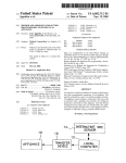
14
INTERACTIVE srrE
APPLIANCE “4m
SERVER
LOCAL
COMPUTER “J12
APPLIAN CE
\
1
10
<_
TRANSFER
0EvICE
<—
l
INTERACTIVE SITE
SERVER
l
16’
12
FIG. 6
LOCAL
COMPUTER
US 6,415,023 B2
1
2
METHOD AND APPARATUS FOR SETTING
PROGRAMMABLE FEATURES OF AN
APPLIANCE
US. Pat. No. 5,774,063 issued to Barry, et al. discloses a
method and apparatus for remote control of electronic
devices from a computer. A transducer, such as an infrared
transmitter, is coupled to a computer and aimed at an
electronic device to be controlled. An application program
BACKGROUND OF THE INVENTION
running on the computer generates appropriate signals for
1. Field of the Invention
control of the electronic device.
US. Pat. No. 5,815,086 issued to Ivie, et al. discloses a
method and apparatus for communicating commands to
This invention relates generally to the ?eld of setting
programmable features of an appliance. More particularly,
the invention provides a method and apparatus for conve
niently setting various programmable features of an appli
10
ances Within a structure, such as a house, are coupled to a
ance using a graphical user interface accessed With a com
signal-conducting bus, such as the AC poWer Wiring bus of
puter via a global computer netWork.
the structure. Appliance commands are issued over the bus
2. Prior Art
The advent of microprocessors and other miniaturiZed
electronics has facilitated the implementation of increas
electrical appliances from remote locations. Various appli
from a central transmitter. Appliances may be directly
15
coupled to the bus or may receive commands via an infrared
signal from an infrared transmitting device coupled to the
ingly complex functions in home and of?ce appliances.
Typically, a relatively complex operator interface is required
bus. A handheld control device may be supplied for con
in order to invoke the various functions that are available.
the handheld control device are coupled to the bus in various
parts of the structure.
US. Pat. No. 5,819,294 issued to Chambers discloses a
trolling the various appliances, in Which case, receivers for
For example, home electronic devices such as televisions,
VCRs, stereo receivers and the like are typically provided
With sophisticated remote control devices. Such remote
control devices have a large number of individual buttons
that are used to directly control features of an appliance
programmable universal remote controller. A programming
device is coupled to a computer and receives signals from
conventional remote controllers. The programming device
and/or that are used to navigate through on-screen menus. 25 correlates the received signals With a database of stored
Due to the sophistication and complexity of the controls,
oWner’s manuals for appliances are becoming increasingly
voluminous and dif?cult to comprehend.
Due to the groWing complexity of modem appliances,
signals used by various appliance manufacturers. The pro
gramming device then sends a complete set of appropriate
control signals to the programmable universal controller.
US. Pat. No. 5,228,077 issued to Darbee discloses a
universal remote controller that may be programmed from a
remote location. The remote controller receives program
ming data via a video or telephonic data transmission
many of the available features are never utiliZed by
consumers, even as competition in the marketplace drives
the proliferation of such features. A number of solutions
have been proposed for making appliances easier to control
and generally more “user friendly”. For example, US. Pat.
No. 5,553,123 issued to Chan, et al. discloses a method for
doWnloading set-up data via a telephone to an appliance
system.
35
controller. Auser ?rst initiates a telephone call to a remote
site having a computer. The user communicates certain
background information to the remote site, and set-up data
is then doWnloaded via the telephone connection. The ear
piece of the telephone is held in proximity to a microphone
built into the appliance controller in order to receive the
doWnloaded data. Upon receipt of the data, the controller is
con?gured to operate the appliance.
US. Pat. No. 5,600,711 issued to Yuen discloses an 45
US. Pat. No. 5,488,571 issued to Jacobs, et al. discloses
a system for transferring data from a video display monitor
of a personal computer to a portable information device such
as an appointment scheduling device. The video display is
modulated to transmit data to an opto-electronic receiver in
the portable information device.
Microsoft Corporation has introduced a cordless phone
having programmable functions controlled by a personal
computer. The base station of the phone is coupled to the
serial port of a computer and application softWare is
installed on the computer to control operation of the phone.
apparatus and methods for providing initialiZing settings to
SUMMARY OF THE INVENTION
an appliance. When a user Wishes to initialiZe the settings of
an appliance, the user initiates a telephone connection With
a remote site. The remote site then doWnloads a sequence of
The present invention provides methods and apparatus for
setting preferences and other parameters of an appliance. In
preferred embodiments of the invention, a user initiates a
connection to an interactive site on a global computer
netWork. The site hosts a graphical user interface With Which
commands for initialiZing the settings in the appliance over
the telephone connection. A remote control device for the
appliance receives the sequence of commands and stores
preferences and other parameters of an appliance may be set
them in an internal memory. The remote control device is
by the user. In some embodiments, set-up data for the
then aimed at the appliance and the user enters a command
appliance is doWnloaded from the user’s computer or the
to transfer the stored sequence of commands to the 55 interactive site directly to the appliance. In other
appliance, thereby initialiZing the settings.
embodiments, set-up data for the appliance is doWnloaded
US. Pat. No. 5,141,756 issued to Levine discloses a
from the user’s computer or the interactive site to a transfer
method of initialiZing a programmable control device, such
device Where it is temporarily stored. The transfer device,
Which is easily portable, is taken by the user to the appliance,
and the set-up data is doWnloaded from the transfer device
to the appliance. Since the appliance itself does not require
a user interface for set-up procedures and programming, the
appliance can be smaller, cheaper and lighter Without sac
ri?cing any functionality. In addition, the need for a printed
user’s manual is largely obviated since all of the information
as a remote controller for a video cassette recorder. The
device is programmed by connecting it to a telephone
system, dialing a remote initialiZing center preferably
employing a computer, and providing the computer With
information as to the environment of the control device by
using touch tone keys to respond to audio inquiries trans
mitted by the computer. The computer then transmits the
initialiZing program for loading into the memory of the
control device.
65
normally contained in such a manual can be obtained from
the interactive site.
US 6,415,023 B2
3
4
BRIEF DESCRIPTION OF THE DRAWINGS
setting the programmable features of appliance 10.
Preferably, server 14 presents to the oWner of appliance 10,
via computer 12, a graphical user interface that is tailored to
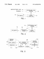
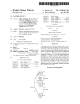
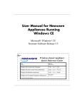
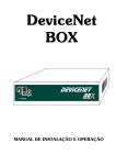
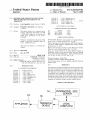
FIG. 1 is a functional block diagram of a ?rst embodiment
of the invention Wherein an appliance receives data directly
appliance 10 and the programmable features thereof. Such
from a local computer.
FIG. 2 is a functional block diagram of a second embodi
ment of the invention Wherein an appliance receives data
from a local computer via a transfer device.
FIG. 3 is a functional block diagram of a transfer device
as shoWn in FIG. 2.
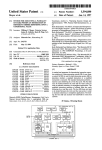
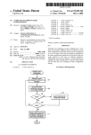
FIG. 4 illustrates a graphical user interface suitable for
interface can be thought of as a “virtual appliance”. This can
be better understood from the discussion of FIG. 4, beloW.
In the embodiment illustrated in FIG. 1, appliance 10 is
directly coupled to local computer 12. The connection
betWeen appliance 10 and computer 12 may be one-Way
from the computer or tWo-Way. One-Way communication
may be accomplished optically by modulating the display of
setting programmable features of a thermostat.
computer 12 as is knoWn in the art. Other communication
techniques can be employed using audio, magnetic,
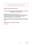
FIG. 5 is a functional block diagram of a third embodi
inductive, infrared, or radio frequency coupling. TWo-Way
ment of the invention Wherein an appliance receives data
15 communications are most conveniently established by con
directly from an interactive site server.
nection to a serial port of computer 12. Naturally, this type
FIG. 6 is a functional block diagram of a fourth embodi
of connection is not convenient for some appliances, but is
ment of the invention Wherein an appliance receives data
particularly Well-suited to portable appliances that may
require a large amount of data. For eXample, loading data
from an interactive site server via a transfer device.
DETAILED DESCRIPTION OF THE
INVENTION
into a pocket organiZer or similar type of personal-digital
assistant can be most conveniently accomplished With a
In the folloWing description, for purposes of explanation
and not limitation, speci?c details are set forth in order to
provide a thorough understanding of the present invention.
HoWever, it Will be apparent to one skilled in the art that the
25
present invention may be practiced in other embodiments
that depart from these speci?c details. In other instances,
detailed descriptions of Well-knoWn methods and devices
may be received periodically as neW model appliances are
released by the manufacturer or may be obtained by server
14 in real time With a dial-up connection to the manufac
are omitted so as to not obscure the description of the present
turer. The latter approach offers the advantage of insuring
invention With unnecessary detail.
The present invention ?nds application With a Wide vari
that the most recent product information is available to
server 14. One method of insuring that the appropriate
information for appliance 10 is obtained by server 14 is to
prompt the appliance oWner to input the serial number of the
ety of home and of?ce appliances. Some categories of
appliances in Which the invention may be utiliZed include
telephones, televisions, video recorders, audio and video
35
entertainment system components, refrigerators, conven
tional ovens, microWave ovens, dishWashers, irrigation
appliance at computer 12. This need only be performed
once, since the serial number can thereafter be stored in
computer 12 and/or server 14 for use in subsequent pro
systems, global positioning satellite (GPS) receivers, auto
mobile heating, ventilating and air conditioning (HVAC)
systems, automobile sound systems, home security systems,
home HVAC systems, home master control systems, fac
simile machines, copiers, postage meters, etc. “Program
mable features” refer to any appliance features that may be
altered. These include, for eXample, initialiZation or set-up
parameters, stored data (e.g., telephone speed dial numbers
serial port connection in the con?guration illustrated in FIG.
1.
In order to provide the appropriate interface for program
ming the features of appliance 10, server 14 preferably
receives data from the appliance manufacturer. Such data
45
or GPS receiver database) and internal softWare. Speci?c
eXamples are given beloW to illustrate operation of the
invention. HoWever, it Will be understood that the invention
has general applicability to appliances of all types and to all
types of programmable features Within such appliances.
A?rst embodiment of the invention is illustrated in FIG.
1. An appliance 10 receives set-up data from a local com
puter 12. In a typical application, local computer 12 is a
gramming of the same appliance.
An optional aspect of the invention is the ability of server
14 to provide valuable feedback to the appliance manufac
turer. During appliance set-up operations, server 14 collects
information concerning consumer’s use of product features
that can be useful in product marketing and neW product
design. The link betWeen server 14 and the appliance
manufacturer also facilitates neW marketing opportunities.
The manufacturer can readily target advertising to identi?ed
purchasers of its products. Also, the manufacturer can offer
accessories and related products for appliance 10. Such
offers may be integrated With the set-up interface or may be
directed to the appliance oWner separately by email or
conventional mail. It should be appreciated that the inven
tion can facilitate Warranty registration. Since the appliance
oWner is already communicating With server 14 to set
general purpose personal computer of the type noW Widely
found in homes and of?ces. Details of computer 12 are not 55
particularly relevant to the invention and are not shoWn.
Typically, computer 12 Will comprise, at a minimum, a
programmable features of the appliance, it is a simple matter
to collect the additional information necessary to complete
Warranty registration and, if desired, to provide additional
processing unit, a keyboard and a display. Additional input
demographic data to the manufacturer.
devices, such as a mouse or other pointing device, and
output devices, such as a printer, may also be included as
tion. This embodiment is similar to that of FIG. 1, eXcept
part of computer 12.
that programming data is provided to appliance 10 by a
Local computer 12 is coupled to a remote interactive site
server 14 by a telecommunications link. In a typical embodi
ment of the invention, interactive site server 14 Would be
transfer device 16. This transfer device receives the pro
gramming data from local computer 12 by a Wired connec
tion to computer 12 or, preferably, by an opto-electronic or
other Wireless data link.
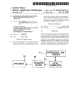
FIG. 3 is a functional block diagram of a suitable transfer
device 16. At the heart of device 16 is a control electronics
accessible via the World Wide Web. Other appropriate
means for connecting computer 12 to server 14 could also be
employed. Server 14 contains programming for interactively
FIG. 2 illustrates an alternative embodiment of the inven
65
US 6,415,023 B2
5
6
module 102. Data modulated on the display screen of
location of the thermostat for transfer of the data. Since all
computer 12 is sensed by optical detector 104 upon activa
tion of receive sWitch 106. The data is demodulated by
electronics 102 and is stored in memory 108. Upon con?r
of the settings have been entered into computer 12, they may
conveniently saved locally and/or by server 14 for subse
quent use in revising these settings or for reloading the
mation of error-free transfer and storage of the data, a
suitable indication is provided to the user by means of
5
settings in the event of a poWer failure. A printed record of
the settings may also be made from computer 12. For some
indicator 110, Which may be, for example, a light emitting
diode (LED). With the data loaded in memory 108, transfer
device 16 may be carried to appliance 10, Which preferably
used as a template for the appliance to indicate selected
includes an infrared receiver coupled to its internal control
electronics. Transfer device 16 is held in proximity to the
appliances may have unlabeled function buttons for Which a
template may be made once selected functions have been
infrared receiver of appliance 10. Upon actuation of transmit
sWitch 112, the data stored in memory 108 is appropriately
modulated by electronics 102 and applied to infrared trans
assigned to the buttons during a set-up procedure.
It Will be appreciated that a thermostat physically incor
porating the interface shoWn in FIG. 4 Would be quite large
and costly in comparison to conventional thermostats. This
is due primarily to the relative complexity of the interface,
since the actual componentry to provide such ?exibility of
mitter 114. Indicator 110 may con?rm to the user that the
data has been transmitted. Alternatively, or in addition, an
appliances, a print-out folloWing a set-up procedure may be
options and programmed features. For example, certain
15
indicator may be provided on appliance 10 to signal receipt
of the data. PoWer source 116, preferably in the form of
common alkaline battery cells, provides electrical poWer to
the components of device 16.
Transfer device 16 may be con?gured in various forms.
Preferably, device 16 is easily portable. Device 16 may be in
the form of a pen or Wand With optical detector 104 and
infrared transmitter 114 at one end. Transfer device 16 may
also be integrated With a conventional remote controller for
thermostat settings is actually quite small and inexpensive.
Through use of the present invention, virtually unlimited
?exibility in thermostat programming may be accomplished
With a thermostat that is no larger and no more costly than
a conventional thermostat. Indeed, a thermostat as just
25
those types of appliances that are commonly controlled
remotely. In another variation, transfer device 16 may be a
described could easily be made the siZe of a postage stamp.
FIG. 5 illustrates another alternative embodiment of the
invention. In this case, data for appliance 10 is received
directly from server 14 rather than local computer 12. From
the appliance oWner’s perspective, the appliance program
removable module of appliance 10. In such case, commu
ming interface is otherWise identical to the previously
nication betWeen the transfer device and the appliance may
be accomplished With a direct electrical connection through
described embodiments. Communication betWeen server 14
a suitable arrangement of electrical contacts. Transfer device
incorporate a conventional modem, in Which case commu
nications may be tWo-Way, or may simply have a data
16 may, in fact, comprise the “brains” of appliance 10 in the
form of a microprocessor or equivalent device. Aside from
the ease of programming features and functions of the
appliance, such an arrangement offers the added bene?t of
facilitating service or replacement of the appliance’s elec
tronic components in the event of malfunction.
The embodiment shoWn in FIGS. 2 and 3 is particularly
Well-suited to appliances that are relatively ?xed in position
and that require only limited amounts of data. Examples of
such appliances abound in the home and of?ce. One such
and appliance 10 may be telephonic. Appliance 10 may
35
demodulator for one-Way communications. Coupling of
appliance 10 to the telecommunications netWork may be by
a conventional RJ-11 connection. Alternatively, appliance
10 may incorporate a cordless telephone module for com
municating With a separate base station. Communications
betWeen server 14 and appliance 10 could also be imple
mented With radio signals. For example, appliance 10 could
incorporate a conventional paging receiver.
A particular example of the embodiment illustrated in
FIG. 3 is a programmable telephone. Speed dial numbers
example is a thermostat for a home HVAC system. FIG. 4
illustrates a graphical user interface for a thermostat as
stood that the particular features of the interface are largely
and other programmable features of a telephone may be
conveniently set using a graphical user interface hosted by
server 14. Once the features have been programmed by the
user, server 14 simply places a call to the telephone. Appro
a matter of design choice.
priate data demodulation circuitry is incorporated in the
presented on a display of computer 12. Such interface is
shoWn merely for purposes of illustration, it being under
45
Along the top of the display shoWn in FIG. 4 is a day strip
telephone in order to doWnload the data from server 14.
FIG. 6 illustrates a further embodiment of the invention
generally similar to that of FIG. 5, but incorporating a
transfer device as in the embodiment of FIG. 2. Here,
122. The user may select any one of the days With a cursor
to program the thermostat settings for that day. BeloW the
day strip is a temperature selector 124. Pointing at the up or
doWn arroW With a mouse or other cursor positioning device,
the user selects the desired temperature. To the right of
temperature selector 124 there are a pair of time WindoWs
126 and 128. Using the appropriate up and doWn arroWs, the
user selects the starting and ending times for Which the
hoWever, transfer device 16‘ receives data directly from
server 14. As With the previously described embodiment,
55
may be telephonic or by radio. One example of a transfer
device 16‘ is embodied as a removable module or “card” of
temperature selection applies.
When the desired settings have been made, the user
selects ENTER button 130 to store the selections and then
proceeds to make the next set of selections. For
convenience, the ending time last entered may be automati
cally inserted into the starting time WindoW. A graphical
display 132 of the selected temperature pro?le may be
provided for the user’s convenience.
When all settings have been completed, the data is loaded
into transfer device 16, Which is then taken to the physical
communication betWeen server 14 and transfer device 16‘
65
a telephone. Data for an appliance 10 is doWnloaded from
server 14 to the telephone Where it is demodulated and
stored in the card. The card may then be taken to appliance
10 to transfer the data to the appliance With an infrared or
other data link.
Another embodiment of the invention as illustrated in
FIG. 6 is a “universal” remote controller that may be
coupled to a telecommunications netWork by means of an
RJ-11 jack or equivalent in the manner disclosed by Darbee
in US. Pat. No. 5,228,077. The remote controller could thus
US 6,415,023 B2
8
7
modulating at least a portion of a display coupled to the
user’s computer;
sensing the modulation With the optical sensor of the
function as a data transfer device in addition to its more
conventional remote control functions.
It Will be recognized that the above described invention
may be embodied in other speci?c forms Without departing
transfer device so as to receive the appliance set-up
from the spirit or essential characteristics of the disclosure.
Thus, it is understood that the invention is not to be limited
data;
doWnloading the appliance set-up data from the output
by the foregoing illustrative details, but rather is to be
port of the transfer device to the real appliance, Wherein
de?ned by the appended claims.
What is claimed is:
1. A method for setting programmable features of an
the real appliance is in a location remote from the user’s
10
appliance comprising the steps of:
providing an interactive site on a global computer net
Work;
providing a graphical user interface at the interactive site,
said graphical user interface having a virtual appliance
15
that graphically depicts programmable features of a
prior to the step of setting programmable features, of enter
corresponding real appliance;
ing a serial number of the real appliance.
5. The method of claim 1 farther comprising the steps of
establishing a connection betWeen a user’s computer and
the interactive site;
extracting information from the set-up data and sending said
entering data With the user’s computer to set program
mable features of the virtual appliance at the interactive
information to a manufacturer of the real appliance.
6. The method of claim 1 Wherein the output port of the
transfer device comprises electrical contacts for mating
engagement With a docking port of the real appliance.
site;
providing a portable transfer device separate from the
user’s computer having an optical sensor and an output
port;
doWnloading the appliance set-up data from the interac
tive site to the user’s computer;
computer.
2. The method of claim 1 Wherein the output port of the
transfer device comprises an infra-red transmitter.
3. The method of claim 1 further comprising the step of
creating a record of the set-up data.
4. The method of claim 1 further comprising the step,
25
7. The method of claim 1 Wherein the interactive site is
accessed via the World Wide Web.