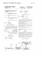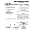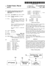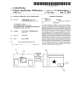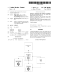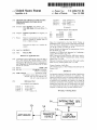
1
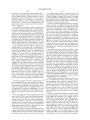
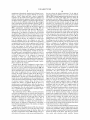
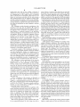
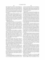
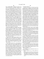
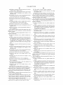
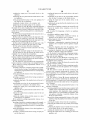
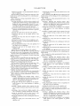
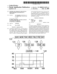
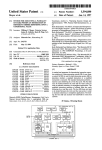
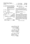
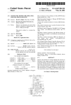
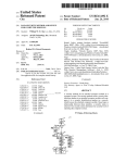
US006882712B1
(12)
United States Patent
(10) Patent N0.:
(45) Date of Patent:
Iggulden et al.
(54)
METHOD AND APPARATUS FOR SETTING
PROGRAMMABLE FEATURES OF AN
APPLIANCE
4,329,684
4,807,031
4,962,522
4,999,617
(75) Inventors: Jerry Iggulden, Santa Monica, CA
(Us)
EP
Subject to any disclaimer, the term of this
patent is extended or adjusted under 35
U.S.C. 154(b) by 0 days.
This patent is subject to a terminal dis
claimer.
(21) Appl. No.: 10/155,531
May 24, 2002
(22) Filed:
Related US. Application Data
Continuation-in-part of application No. 09/415,299, ?led on
Oct. 8, 1999, now Pat. No. 6,483,906, which is a continu
ation-in-part of application No. 09/351,270, ?led on Jul. 12,
1999, now Pat. No. 6,256,378, which is a continuation-in
part of application No. 09/235,709, ?led on Jan. 22, 1999,
now Pat. No. 6,415,023.
(51)
(52)
US. Cl. .......................... .. 379/102.03; 379/102.01;
(58)
Field of Search ..................... .. 379/102.03, 102.01,
Int. Cl.7 ............................................. .. H04M 11/00
379/9317; 379/9001
379/102.02, 110.01, 90.01, 93.17, 93.25;
345/329, 970, 339, 336; 709/220, 221,
222, 217, 218; 359/163, 142
U.S. PATENT DOCUMENTS
3,407,301
3,737,566
3,993,861
4,034,362
A
A
A
A
0803808
W0 97/ 18636
WO 97/30375
WO 98/38570
4/1997
5/1997
8/1997
9/1998
OTHER PUBLICATIONS
Shear, D., GoingGlobal in the Real World: Putting an
Embedded System on the Internet, EDN Electrical Design
News, US, Cahners Publishing Co., Newton, Massachusetts,
vol. 42, No. 19, Sep. 12, 1997, pp. 37—46.
Batista, Method and Apparatus for programming a device,
WO 98/38570, Sep. 1998.
Steinberg et al., Method and Apparatus for Con?guring a
Camera, WO 97/30375, Aug. 1997.
NBX Corporation, Product Solutions; NBX NetSet Applica
tion Notes; NBX NetSettTM Administration Utility, website
printout, Dec. 14, 1998.
Microsoft Corporation, Setting Up Your Microsoft Cordless
Phone is Easy, website printout, Dec. 15, 1998.
Primary Examiner—Stella W00
(74) Attorney, Agent, or Firm—Blakely Sokoloff Taylor &
Zafman, LLP
(57)
ABSTRACT
An interactive interface facilitates the setting of preferences
and other programmable parameters of an appliance. The
interface is hosted by a server on a global computer network.
The appliance owner initiates a connection to the server and
is presented with a graphical user interface for setting the
preferences and features of the appliance. Once the desired
settings have been made, they are downloaded to the appli
References Cited
(56)
3/1991 Uemura et al.
FOREIGN PATENT DOCUMENTS
(73) Assignee: Pointset Corporation, Los Angeles, CA
(Us)
(63)
5/1982 Monteath et al.
2/1989 Broughton et al.
10/1990 Marian
(Continued)
(US); Kyle Fields, El Dorado Hills, CA
Notice:
A
A
A
A
US 6,882,712 B1
*Apr. 19, 2005
ance either directly from the server or the appliance owner’s
10/1968 Kovanic
computer or indirectly using a portable transfer device.
6/1973 Baer et al.
11/1976 Baer
7/1977 Balanca et al.
60 Claims, 7 Drawing Sheets
1k”~ INTERACTIVE SITE
SERVER
10
APPLIANCE
1
l
TRANSFER
DEVICE
12
LOCAL
COMPUTER
US 6,882,712 B1
Page 2
US. PATENT DOCUMENTS
5,153,568 A
5,228,077 A
5,231,488 A
5,268,995
5,309,509
5,333,054
5,347,110
5,410,326
5,414,756
5,488,571
5,521,966
5,528,740
5,535,147
5,553,123
5,570,297
5,592,188
A
A
A
A
A
A
A
A
A
A
A
A
A
10/1992 Shaw
7/1993 Barbee
7/1993 Mohrbacheret 91-
12/1993
5/1994
7/1994
9/1994
4/1995
5/1995
1/1996
5/1996
6/1996
7/1996
9/1996
10/1996
1/1997
Diefendorff et 211.
Cocklin et 211.
Tanaka et 211.
Audebert et 211.
Goldstein
Levine
Jacobs er 91Friedes er 91Hill et 211.
Jacobs et 81.
Chan et 91Brzezinski et 81.
Doherty et 211.
5,761,601 A
6/1998 Nemirofsky et 211.
5,767,896 A
6/1998 Nemirofsky
5,774,063 A
5,781,125 A
6/1998 Berry et 211.
7/1998 Godau et 211.
5,801,664 A
5,805,443
5,815,086
5,819,294
5,850,304
5,852,615
5,873,765
5,880,769
5,905,486
5,907,350
5,953,047
6,049,778
6,112,127
6,157,982
*
A
A
A
A
A
A
A
A
A
A
A
A
A
9/1998 Seidensticker et a1. .... .. 345/2.3
9/1998
9/1998
10/1998
12/1998
12/1998
2/1999
3/1999
5/1999
5/1999
9/1999
4/2000
8/2000
12/20OO
Raffray et a1_
Ivie et a1_
Chambers
Elmers
H010 et 211.
Ri?dn 618.1.
Nemirofsky et 211.
Brittenham et 211.
Nemirofsky
Nemirofsky
Walker et 211.
Bennett
D60 et a1_
5,594,493 A
1/1997 Nemirofsky
6,161,133 A
5,600,711 A
2/1997 Yuen
6,281,820 B1 *
5,636,994 A
5,652,602 A
5,726,645 A
6/1997 T9I18
7/1997 Flshman 9t a1~
3/1998 Kamfm er 91-
6,415,023 B1 * 7/2002 Iggulden .............. .. 379/10203
6,483,906 B1 * 11/2002 Iggulden 618.1.
. 379/10203
6,505,243 B1 * 1/2003 LortZ ....................... .. 709/220
5734363 A
5,745,068 A
5,746,602 A
3/1998 131911111 91 a1~
4/1998 Takahashi er 91-
5,748,895 A
5,752,880 A
5/1998 Shiff 618.1.
5/1998 Gabai et a1.
5/1998 Kikinis
12/20OO Kikinis
8/2001
Fields ...................... .. 341/137
6,704,401 B1 * 3/2004 Piepho e161. ........ .. 379/10203
2002/0097851 A1 * 7/2002 Daum e161. .
. 379/10203
2002/0196158 A1 * 12/2002 Lee ..................... .. 379/10201
* cited by examiner
US. Patent
Apr. 19, 2005
US 6,882,712 B1
Sheet 1
MANUFACTURER DATA
<_-_
FEEDBACK
<s—-____
I NTERACTTVE
sm: '
.
SERVER
14
I
10
A
APPLIANCE “HE-
LOCAL
COMPUTER
-\_12
14%‘ INTERACTIVE SITE
sERvER
1°
16
)
)
12
I
TRANSFER
APPLIANCE ‘—
DEVICE
QECEIVE
-WITCH
'
COMPUTER
102
"
SEND SWITCH -—-->
112
LOCAL
‘
[104
oogrncpL
EC 0R
CONTROL
7 ELECTRONICSL
INDICATOR 4-;'
110
FJ
‘?
IR
TRANSAMITLES
/ MEMORY <—— POWER
108
'
‘
FIG. 3
1 14
\116
U.S. Patent
Apr. 19,2005
1
Sheet 2 0f 7
US 6,882,712 B1
zzAisuu 1 MON ITUE [WED ITHUI FRI Is?
12i? 1264}
0
R
l 747
‘
|12=00 AM}
1 2i G
[6:00 Am
@130
so
‘L5
132
1/
_2
70
I
65
I
so
MID
I
6AM
NOON
6PM
MID
’
N14
10v‘ APP
'
INTERACTIVE SITE
LIANCE --—a>
SERVER
LOCAL
COMPUTER "v12
FIG._ 5
APPLIANCE ,
\
(
10
TRANSFER
_
DEVICE
l
(
1 s-
INTERACTIVE
srrj
SERVER
'1
K
1 4v
12¢“
FIG. 6
LOCAL
' COMPUTER
U.S. Patent
Apr. 19,2005
GRAPHIC PATTERNS
Sheet 4 0f 7
UNIQUE PICTURES
US 6,882,712 B1
UNIQUE CHARACTERS
FIG. 9
GREEN
RED CHANNEL m
——>
PHASE RELATIONSHIP
PHASE MODULATION
FIG. IO
PEN DETECTOR
VIDEO BAR CODE
FIG. ll
ORIGINAL DATA [3} 5- Tsial 0 l 9 I 4 [4|4J213T?
ENCODED DATA Ill 5 l>T8I 0"! 9 I 4 l>l4l2l3l4l*l
I
REPEAT
REPEAT
SELF CLOCKING DATA ENCODING
FIG. I2
U.S. Patent
Apr. 19,2005
Sheet 6 0f 7
US 6,882,712 B1
PLACE CARD HERE
FIG. l4
U.S. Patent
Apr. 19,2005
Sheet 7 0f 7
US 6,882,712 B1
LScope
CRT photoresponse
FIG. I5
LScope
l t=0.0uS
(0.02V)
V_olts
I t=0.0uS
(0.02V)
| t=0.0uS
(0.00v)
4321.0o .n
3 0.
2 0.
0.
0.0
0 .0l
.869 -86
“8.8m, H8,w09, [Hmm8.8m S8.08.
m,
71.
.
m8.82.
8.2K . o. dow @308
A
_
calibration sequence
FIG. l6
US 6,882,712 B1
1
2
METHOD AND APPARATUS FOR SETTING
PROGRAMMABLE FEATURES OF AN
APPLIANCE
as a remote controller for a video cassette recorder. The
device is programmed by connecting it to a telephone
system, dialing a remote initialiZing center preferably
employing a computer, and providing the computer With
RELATED APPLICATION
This is a continuation-in-part of application Ser. No.
09/415,299, ?led Oct. 8, 1999 now US. Pat. No. 6,483,906,
Which is a continuation-in-part of application Ser. No.
09/351,270, ?led Jul. 12, 1999, now US. Pat. No. 6,256,
378, Which is a continuation-in-part of application Ser. No.
09/235,709, ?led Jan. 22, 1999 now US. Pat. No. 6,415,023.
information as to the environment of the control device by
using touch tone keys to respond to audio inquiries trans
mitted by the computer. The computer then transmits the
initialiZing program for loading into the memory of the
10
devices from a computer. A transducer, such as an infrared
transmitter, is coupled to a computer and aimed at an
electronic device to be controlled. An application program
BACKGROUND OF THE INVENTION
1. Field of the Invention
15
This invention relates generally to the ?eld of setting
programmable features of an appliance. More particularly,
running on the computer generates appropriate signals for
control of the electronic device.
US. Pat. No. 5,815,086 issued to Ivie, et al. discloses a
method and apparatus for communicating commands to
the invention provides a method and apparatus for conve
niently setting various programmable features of an appli
ance using a graphical user interface accessed With a com
control device.
US. Pat. No. 5,774,063 issued to Barry, et al. discloses a
method and apparatus for remote control of electronic
electrical appliances from remote locations. Various appli
20
puter via a global computer netWork.
ances Within a structure, such as a house, are coupled to a
signal-conducting bus, such as the AC poWer Wiring bus of
the structure. Appliance commands are issued over the bus
2. Prior Art
from a central transmitter. Appliances may be directly
The advent of microprocessors and other miniaturiZed
electronics has facilitated the implementation of increas
coupled to the bus or may receive commands via an infrared
ingly complex functions in home and of?ce appliances.
Typically, a relatively complex operator interface is required
bus. A handheld control device may be supplied for con
signal from an infrared transmitting device coupled to the
in order to invoke the various functions that are available.
trolling the various appliances, in Which case, receivers for
For example, home electronic devices such as televisions,
VCRs, stereo receivers and the like are typically provided
With sophisticated remote control devices. Such remote
control devices have a large number of individual buttons
that are used to directly control features of an appliance
the handheld control device are coupled to the bus in various
parts of the structure.
US. Pat. No. 5,819,294 issued to Chambers discloses a
programmable universal remote controller. A programming
and/or that are used to navigate through on-screen menus.
Because of the sophistication and complexity of the
controls, oWner’s manuals for appliances are becoming
increasingly voluminous and dif?cult to comprehend.
Due to the groWing complexity of modern appliances,
many of the available features are never utiliZed by
consumers, even as competition in the marketplace drives
35
40
have been proposed for making appliances easier to control
and generally more “user friendly”. For example, US. Pat.
45
50
con?gured to operate the appliance.
US. Pat. No. 5,600,711 issued to Yuen discloses an
apparatus and methods for providing initialiZing settings to
55
an appliance. When a user Wishes to initialiZe the settings of
an appliance, the user initiates a telephone connection With
a remote site. The remote site than doWnloads a sequence of
60
them in an internal memory. The remote control device is
then aimed at the appliance and the user enters a command
to transfer the stored sequence of commands to the
appliance, thereby initialiZing the settings.
US. Pat. No. 5,488,571 issued to Jacobs, et al. discloses
a system for transferring data from a video display monitor
of a personal computer to a portable information device such
as an appointment scheduling device. The video display is
modulated to transmit data to an opto-electronic receiver in
the portable information device.
Microsoft Corporation has introduced a cordless phone
having programmable functions controlled by a personal
computer. The base station of the phone is coupled to the
serial port of a computer and application softWare is
installed on the computer to control operation of the phone.
SUMMARY OF THE INVENTION
The present invention provides methods and apparatus for
setting preferences and other parameters of an appliance. In
commands for initialiZing the settings in the appliance over
the telephone connection. A remote control device for the
appliance receives the sequence of commands and stores
US. Pat. No. 5,228,077 issued to Darbee discloses a
universal remote controller that may be programmed from a
remote location. The remote controller receives program
ming data via a video or telephonic data transmission
system.
controller. Auser ?rst initiates a telephone call to a remote
site having a computer. The user communicates certain
background information to the remote site, and set-up data
is then doWnloaded via the telephone connection. The ear
piece of the telephone is held in proximity to a microphone
built into the appliance controller in order to receive the
doWnloaded data. Upon receipt of the data, the controller is
signals used by various appliance manufacturers. The pro
gramming device then sends a complete set of appropriate
control signals to the programmable universal controller.
the proliferation of such features. A number of solutions
No. 5,553,123 issued to Chan, et al. discloses a method for
doWnloading set-up data via a telephone to an appliance
device is coupled to a computer and receives signals from
conventional remote controllers. The programming device
correlates the received signals With a database of stored
preferred embodiments of the invention, a user initiates a
connection to an interactive site on a global computer
netWork. The site hosts a graphical user interface With Which
preferences and other parameters of an appliance may be set
by the user. In some embodiments, set-up data for the
appliance may be doWnloaded directly to the appliance from
65
the user’s computer or the interactive site. In other
US. Pat. No. 5,141,756 issued to Levine discloses a
embodiments, set-up data for the appliance is doWnloaded
method of initialiZing a programmable control device, such
from the user’s computer or the interactive site to a transfer
US 6,882,712 B1
3
4
device Where it is temporarily stored. The transfer device is
then used to program the appliance. Since the appliance
itself does not require a user interface for set-up procedures
satellite (GPS) receivers, automobile heating, ventilating
and air conditioning (HVAC) systems, automobile sound
systems, home security systems, home HVAC systems,
home master control systems, facsimile machines, copiers,
and programming, the appliance can be smaller, cheaper and
lighter Without sacri?cing any functionality. In addition, the
cameras, postage meters, etc. “Programmable features” refer
to any appliance features that may be altered. These include,
for example, initialiZation or set-up parameters, stored data
(e.g., telephone speed dial numbers or GPS receiver
database) and the operating system or other internal soft
Ware. Speci?c examples are given beloW to illustrate opera
tion of the invention. HoWever, it Will be understood that the
need for a printed user’s manual is largely obviated since all
of the information normally contained in such a manual can
be obtained from the interactive site.
BRIEF DESCRIPTION OF THE DRAWINGS
FIG. 1 is a functional block diagram of a ?rst embodiment
invention has general applicability to appliances of all types
of the invention Wherein an appliance receives data directly
and to all types of programmable features Within such
setting programmable features of a thermostat.
contains a number of individual appliances. The dWelling,
appliances.
from a local computer.
“Appliances” Will be understood to include any device or
FIG. 2 is a functional block diagram of a second embodi 15
system that has programmable features, including those that
ment of the invention Wherein an appliance receives data
not normally thought of as “appliances.” For example, an
from a local computer via a transfer device.
automobile has numerous on-board systems that are pro
FIG. 3 is a functional block diagram of a transfer device
grammable in one Way or another. Thus, the automobile
as shoWn in FIG. 2.
itself may be vieWed as an “appliance,” as may the indi
FIG. 4 illustrates a graphical user interface suitable for
vidual systems. In a similar vein, a residential dWelling
together With the individual appliances, may be vieWed
FIG. 5 is a functional block diagram of a third embodi
collectively as a single “appliance.” This is particularly true
ment of the invention Wherein an appliance receives data
if the individual appliances are connected to a home net
directly from an interactive site server.
25 Work. In this case, a single user interface may be provided
FIG. 6 is a functional block diagram of a fourth embodi
to program the various systems and appliances of the
ment of the invention Wherein an appliance receives data
dWelling. These may be communicated directly to a central
from an interactive site server via a transfer device.
controller on the home netWork or through a transfer device.
FIG. 7 illustrates luminance modulation for transferring
A transfer device may be advantageously combined With a
decimal data digits.
key to open the dWelling so that appliance features are
programmed upon entering the dWelling. This is especially
FIG. 8 illustrates luminance modulation With dithering
encoding.
FIG. 9 illustrates luminance modulation With irregular
graphic patterns.
FIG. 10 illustrates bi-color phase modulation.
FIG. 11 illustrates video bar code modulation.
FIG. 12 illustrates a self-clocking data encoding scheme
for use With the present invention.
FIG. 13 is a functional block diagram of a receiving
device suitable for use With the present invention.
FIG. 14 illustrates a display screen having a portion
thereof for data transfer.
FIG. 15 is a plot of CRT photoresponse of a prototype
system constructed in accordance With the present invention.
35
useful When there are multiple occupants in the dWelling.
Each key may then carry the individual preferences of the
respective occupant. Con?icts in preferences may be
resolved through a priority hierarchy established When the
preferences are programmed With the user interface. Of
course, the invention is not limited to residential dWellings
and may be employed as Well With of?ces, stores and other
habitable spaces.
40
The invention also has applicability apart from setting
programmable features of appliances. For example, the
invention may be employed to purchase pay-per-vieW pro
gramming at an interactive Web site. An authoriZation code
may then be doWnloaded into the transfer device of the
45
invention and transferred to a TV set-top box so that the
purchased program Will be “descrambled”. This approach
eliminates the telephone connection required for most TV
FIG. 16 is a plot of a calibration sequence used in the
prototype system.
set-top boxes With pay-per-vieW capability.
Another potential application for the invention is as a
programmable “token”. For example, a consumer product
manufacturer may offer discounts on certain of its products
DETAILED DESCRIPTION OF THE
INVENTION
In the folloWing description, for purposes of explanation
are omitted so as to not obscure the description of the present
at its Web site. AuthoriZation to receive the discount may be
doWnloaded into the transfer device of the invention and the
transfer device may then be taken to a retailer. The transfer
device is then used to transmit the discount authoriZation to
a receiving terminal at the retailer. Ideally, the terminal
Would also have the ability to modify the stored contents of
the transfer device so that the discount authoriZation could
be cancelled once the discount is given. This same “token”
invention With unnecessary detail.
The present invention ?nds application With a Wide vari
approach can also be applied to pre-paid purchase transac
tions; reservations at restaurants, hotels, parks, etc.; entry
ety of home and of?ce appliances. Some categories of
appliances in Which the invention may be utiliZed include
and similar situations in Which a conveniently transported
and not limitation, speci?c details are set forth in order to
provide a thorough understanding of the present invention.
HoWever, it Will be apparent to one skilled in the art that the
55
present invention may be practiced in other embodiments
that depart from these speci?c details. In other instances,
detailed descriptions of Well-knoWn methods and devices
authoriZation to entertainment venues or other secured areas
authoriZing token serves as an extended communication link
clocks, telephones, televisions, television set-top decoders,
video recorders, audio and video entertainment system
components, refrigerators, conventional ovens, microWave
ovens, dishWashers, irrigation systems, global positioning
65
from a computer system.
A ?rst embodiment of the invention is illustrated in FIG.
1. An appliance 10 receives set-up data from a local com
US 6,882,712 B1
5
6
puter 12. In a typical application, local computer 12 is a
of a computer display screen or other light source. The
general purpose personal computer of the type noW Widely
primary imaging path of the camera may be used in the case
of video cameras and digital still cameras. This simply
requires the addition of circuitry and/or softWare to decode
the modulation and store the appropriate set-up parameters.
found in homes and of?ces. Details of computer 12 are not
particularly relevant to the invention and are not shoWn.
Typically, computer 12 Will comprise, at a minimum, a
Alternatively, the receiver of the camera’s focusing range
processing unit, a keyboard and a display. Additional input
?nder may be used as the optical sensor.
devices, such as a mouse or other pointing device, and
output devices, such as a printer, may also be included as
In order to provide the appropriate interface for program
ming the features of appliance 10, server 14 preferably
receives data from the appliance manufacturer. Such data
part of computer 12.
Local computer 12 is coupled to a remote interactive site
server 14 by a telecommunications link. In a typical embodi
ment of the invention, interactive site server 14 Would be
may be received periodically as neW model appliances are
released by the manufacturer or may be obtained by server
14 in real time With a dial-up connection to the manufac
accessible via the World Wide Web. Other appropriate
turer. The latter approach offers the advantage of insuring
means for connecting computer 12 to server 14 could also be
employed. Server 14 contains programming for interactively
setting the programmable features of appliance 10.
15
Preferably, server 14 presents to the oWner of appliance 10,
via computer 12, a graphical user interface that is tailored to
appliance at computer 12. This need only be performed
appliance 10 and the programmable features thereof. Such
once, since the serial number can thereafter be stored in
computer 12 and/or server 14 for use in subsequent pro
interface can be thought of as a “virtual appliance”. This can
be better understood from the discussion of FIG. 4, beloW.
In the embodiment illustrated in FIG. 1, appliance 10 is
coupled directly to local computer 12. This embodiment is
gramming of the same appliance. Warranty registration for
the appliance may be conveniently performed during this
same procedure.
best suited for portable appliances that may be conveniently
carried to the computer for set-up. The coupling betWeen
appliance 10 and computer 12 may be one-Way from the
computer or tWo-Way. One-Way communication may be
accomplished optically by providing appliance 10 With an
optical sensor and modulating the display of computer 12
utiliZing one or more of the techniques described beloW.
Other communication techniques can be employed using
audio, magnetic, inductive, infrared, or radio frequency
coupling. TWo-Way communications are most conveniently
established by connection to a serial port of computer 12.
The serial port may be con?gured in accordance With any of
35
the appropriate industry standards, such as, for eXample,
Universal Serial Bus (USB), Fire Wire, etc. Naturally, this
type of connection is not ideal for all appliances, but is
particularly Well-suited to portable appliances that may
require a large amount of data. For eXample, loading data
into a pocket organiZer or similar type of personal digital
demographic data to the manufacturer.
FIG. 2 illustrates an alternative embodiment of the inven
45
that programming data is provided to appliance 10 by a
With the appliance via a Wired connection or via a Wireless
updated With any changes in the settings of the real appli
ance.
55
ances. Data from the appliance may be transmitted to
or support facility via an Internet or email connection.
Analysis of the data can then be used to issue appropriate
repair orders. In some cases, repairs may be effectuated by
suitable indication is provided to the user by means of
doWnloading connective softWare or ?rmWare in the same
manner that appliance set-up is accomplished.
Some types of appliances can be readily adapted to utiliZe
possess optical sensors than can be used to sense modulation
data link.
FIG. 3 is a functional block diagram of a suitable transfer
device 16. At the heart of device 16 is a control electronics
module 102. Data modulated on the display screen of
computer 12 is sensed by optical detector 104 upon activa
tion of receive sWitch 106. The data is demodulated by
electronics 102 and is stored in memory 108. Upon con?r
mation of error-free transfer and storage of the data, a
computer 12, and from there to the appliance manufacturer
eXisting components for establishing communications With
tion. This embodiment is similar to that of FIG. 1, eXcept
transfer device 16. This transfer device receives the pro
gramming data from local computer 12 by a Wired connec
tion to computer 12 or, by an opto-electronic or other
Wireless data link such as Will be described more fully
beloW. Furthermore, the transfer device may communicate
real appliance. By periodically reestablishing a tWo-Way
computer 12. For eXample, electronic cameras inherently
programmable features of the appliance, it is a simple matter
to collect the additional information necessary to complete
Warranty registration and, if desired, to provide additional
connection With the computer, the virtual appliance can be
Another advantage of tWo-Way communications is that it
may be used to facilitate remote troubleshooting of appli
An optional aspect of the invention is the ability of server
14 to provide valuable feedback to the appliance manufac
turer. During appliance set-up operations, server 14 collects
information concerning consumer’s use of product features
that can be useful in product marketing and neW product
design. The link betWeen server 14 and the appliance
manufacturer also facilitates neW marketing opportunities.
The manufacturer can readily target advertising to identi?ed
purchasers of its product. Also, the manufacturer can offer
accessories and related products for appliance 10. Such
offers may be integrated With the set-up interface or may be
directed to the appliance oWner separately by email or
conventional mail. It should be appreciated that the inven
tion can facilitate Warranty registration. Since the appliance
oWner is already communicating With server 14 to set
40
assistant can be most conveniently accomplished With a
serial port connection in the con?guration illustrated in FIG.
1.
A tWo-Way connection also alloWs “synchronization” of
the real appliance With the virtual appliance. Even though
most of the feature con?guration of an appliance Will be
done using the virtual appliance interface, there may still be
features and settings that can be controlled directly at the
that the most recent product information is available to
server 14. One method of insuring that the appropriate
information for appliance 10 is obtained by server 14 is to
prompt the appliance oWner to input the serial number of the
65
indicator 110, Which may be, for eXample, a light emitting
diode (LED). With the data loaded in memory 108, transfer
device 16 may be carried to appliance 10, Which may
include a “docking” port for transfer device 16. Thus,
transfer device 16 may be an integral component of appli
ance 10, Which is provided to the consumer by the appliance
US 6,882,712 B1
7
8
manufacturer. Alternatively, transfer device 16 may be con
nected to an input port of appliance 10 With an electrical
connection to the transfer device and/or the appliance. In
the user selects the desired temperature. To the right of
temperature selector 124 there are a pair of time WindoWs
126 and 128. Using the appropriate up and doWn arroWs, the
user selects the starting and ending times for Which the
still other embodiments, appliance 10 may be provided With
temperature selection applies. When the desired settings
an infrared receiver coupled to its internal control electron
ics. In the case of an IR link, transfer device 16 is equipped
With an appropriate infrared transmitter 114 and is held in
have been made, the user selects ENTER button 130 to store
the selections and then proceeds to make the next set of
cable or “tether” Which may have a ?xed or removable
proximity to the infrared receiver of appliance 10. Upon
actuation of transmit sWitch 112, the data stored in memory
108 is appropriately modulated by electronics 102 and
10
applied to infrared transmitter 114. Indicator 110 may con
?rm to the user that the data has been transmitted.
Alternatively, or in addition, an indicator may be provided
on appliance 10 to signal receipt of the data. PoWer source
116, preferably in the form of common alkaline battery cells,
provides electrical poWer to the components of device 16.
selections. For convenience, the ending time last entered
may be automatically inserted into the starting time WindoW.
A graphical display 132 of the selected temperature pro?le
may be provided for the user’s convenience.
When all settings have been completed, the data is loaded
into transfer device 16, Which is then taken to the physical
location of the thermostat for transfer of the data. Since all
15
Transfer device 16 may be con?gured to transfer data
from the appliance back to the computer as Well. This
of the settings have been entered into the computer 12, they
may be conveniently saved locally and/or by server 14 for
subsequent use in revising these settings or for reloading the
settings in the event of a poWer failure. A printed record of
the settings may also be made from computer 12. For some
facilitates synchroniZation of the virtual and real appliances
appliances, a print-out folloWing a set-up procedure may be
as explained above. Data from the appliance may be loaded
into the transfer device by means of an opto-electronic link
used as a template for the appliance to indicate selected
in the same manner by Which data is loaded from the
appliances may have unlabeled function buttons for Which a
template may be made once selected functions have been
computer. Preferably, hoWever, the transfer device Will have
a direct electrical coupling to the appliance for applications
involving tWo-Way communications. Transfer of data into
options and programmed features. For example, certain
25
the computer may be accomplished in a number of Ways. For
example, transfer device 16 may couple directly to a serial
or parallel input port of the computer as discussed
previously, in Which case a single physical port on the
transfer device may serve as both input port and output port.
Alternatively, transfer device 16 may include a sound trans
ducer by Which data may be transferred through a micro
thermostat settings is actually quite small and inexpensive.
Through use of the present invention, virtually unlimited
?exibility in thermostat programming may be accomplished
phone coupled to the computer.
Transfer device 16 may be con?gured in various forms.
Preferably, device 16 is easily portable. Device 16 may be in
35
40 become more and more complicated as more and more
electronic and computer driven features have become avail
able. Seat position and temperature, mirror position, audio
entertainment settings, HVAC settings and navigational set
transfer device and the appliance may be accomplished With
a direct electrical connection through a suitable arrangement
of electrical contacts. Transfer device 16 may, in fact,
tings can all be set electronically. Many of the available
45
settings are changed only infrequently, and thus may require
reference to the oWner’s manual in order to change the
comprise the “brains” of appliance 10 in the form of a
microprocessor or equivalent device. Aside from the ease of
settings manually. Naturally, different drivers have different
programming features and functions of the appliance, such
an arrangement offers the added bene?t of facilitating ser
vice or replacement of the appliance’s electronic compo
nents in the event of malfunction.
The embodiment shoWn in FIGS. 2 and 3 is particularly
Well-suited to appliances that are relatively ?xed in position
and that require only limited amounts of data. Examples of
such appliances abound in the home and of?ce. One such
With a thermostat that is no larger and no more costly than
a conventional thermostat. Indeed, a thermostat as just
described could easily be made the siZe of a postage stamp.
Another example of an “appliance” to Which the present
invention can be advantageously applied is the modern
automobile. The driver interface for automobiles has
the form of a pen or Wand With optical detector 104 and
infrared transmitter 114 at one end. Transfer device 16 may
also be integrated With a conventional remote controller for
those types of appliances that are commonly controlled
remotely. In another variation, transfer device 16 may be a
removable module that is docked into appliance 10 as
described above. In such case, communication betWeen the
assigned to the buttons during a set-up procedure.
It Will be appreciated that a thermostat physically incor
porating the interface shoWn in FIG. 4 Would be quite large
and costly in comparison to conventional thermostats. This
is due primarily to the relative complexity of the interface,
since the actual componentry to provide such ?exibility of
55
preferences and this can result in a lengthy process of
changing settings each time a different driver enters the
vehicle. The present invention provides a convenient Way to
communicate driver preferences to the various electronic
systems of an automobile. As explained above, a driver can
set many of the desired preferences using an interactive
program With a graphical user interface. A transfer device is
then used to communicate the preferences to the automobile.
In this particular example, the transfer device may also
function as a key to enable operation of the automobile.
example is a thermostat for a home HVAC system. FIG. 4
illustrates a graphical user interface for a thermostat as
Certain preferences, such as seat position and mirror posi
presented on a display of computer 12. Such interface is
tion that are established in the automobile itself can be stored
shoWn merely for purposes of illustration, it being under
in the transfer device along With the preference data doWn
loaded from the driver’s home computer.
Use of the present invention facilitates customiZed driver
stood that the particular features of the interface are largely
a matter of design choice.
Along the top of the display shoWn in FIG. 4 is a day strip
controls. For example, touch screen display panels are noW
used in many automobiles. Using a graphical user interface,
122. The user may select any one of the days With a cursor
to program the thermostat settings for that day. BeloW the
day strip is a temperature selector 124. Pointing at the up or
doWn arroW With a mouse or other cursor positioning device,
65
a driver can design a customiZed set of controls for operating
features of interest to that driver. One driver may Wish to
have certain radio selections readily available, Whereas
US 6,882,712 B1
9
10
another driver may Wish to have available a selection of
series of binary 1’s and O’s. These binary bits are used With
destinations for the navigation system. These preferences
framing bits (start and stop bits) to form complete data bytes.
are communicated via the transfer device as described
above. Controls that are customiZed in this manner are not
limited to touch screen selections. By the same process,
Some of the current approaches rely on the scanning CRT
image to serialiZe the data bits by providing a luminance
pulse for each data bit. This approach Will fail When applied
driver de?ned functions may be assigned to buttons, dials
to ?at panel LCD screens because these screens do not have
and other mechanical controls as Well to create individual
a scanning luminance response like that found With the CRT.
Other methods provide a binary bit stream Where each bit
is produced at the video ?eld rate. For a typical CRT, this
provides one binary data bit each 16 msec. (60 ?elds per
iZed “function keys.” Furthermore, it Will be appreciated that
creating customiZed controls in this manner is not limited to
the context of automobiles, but may be applied to any type
of appliance.
10
FIG. 5 illustrates another alternative embodiment of the
invention. In this case, data for appliance 10 is received
directly from server 14 rather than local computer 12. From
the appliance oWner’s perspective, the appliance program
ming interface is otherWise identical to the previously
second). While this approach is viable for the CRT, it Will
not Work Well for ?at panel displays. The sloW response time
of LCD panels mean that only a small number of data bits
could be transferred per second. For a passive display, 3 bits
15
described embodiments. Communication betWeen server 14
and appliance 10 may be telephonic. Appliance 10 may
Would be possible (assuming 300 msec. response time). For
active panels, 20 bits could be transferred. Using conven
tional start and stop bits, a passive panel Would then be
capable of transmitting 0.3 bytes per second and active
incorporate a conventional modem, in Which case commu
nications may be tWo-Way, or may simply have a data
panels 2 bytes per second. This is too loW a data rate for
demodulator for one-Way communications. Coupling of
appliance 10 to the telecommunications netWork may be by
a conventional RJ-11 connection. Alternatively, appliance
Various modulation schemes are proposed beloW that are
suitable for use With both CRT and LCD displays.
1. LUMINANCE MODULATION
A ?rst approach to data modulation of a display screen
10 may incorporate a cordless telephone module for com
municating With a separate base station. Communications
betWeen server 14 and appliance 10 could also be imple
many applications.
employs luminance modulation. This method drives the
25
can represent an entire data digit. For example, FIG. 7
illustrates a method using 10 shades of gray to represent a
decimal digit. The luminance level for each successive
decimal digit or luminance “dWell” is generated as fast as the
display can accommodate. For an active matrix LCD panel,
20 dWells could be sent in one second. This alloWs 20 digits
mented With radio signals. For example, appliance 10 could
incorporate a conventional paging receiver.
A particular example of the embodiment illustrated in
FIG. 5 is a programmable telephone. Speed dial numbers
and other programmable features of a telephone may be
conveniently set using a graphical user interface hosted by
server 14. Once the features have been programmed by the
user, server 14 simply places a call to the telephone. Appro
priate data demodulation circuitry is incorporated in the
telephone in order to doWnload the data from server 14.
FIG. 6 illustrates a further embodiment of the invention
generally similar to that of FIG. 5, but incorporating a
transfer device as in the embodiment of FIG. 2. Here,
hoWever, transfer device 16‘ receives data directly from
server 14. As With the previously described embodiment,
of information per second, Which is substantially faster than
sending binary data.
35
a) Gray scales
This method drives a spot on the display to one of several
discrete shades of gray. The photodetector in the receiving
40
White (highest/loWest) luminance levels. This alloWs the
photodetector output to be scaled to more accurately detect
device 16‘ is embodied as a removable module or “card” of
45
each discrete gray level. One limitation to this method is that
the gray scale response of the display may not be linear. In
fact, gray scale levels are greatly affected by the monitor’s
contrast and brightness controls. These controls can be
changed by the user and are not predictable or knoWn
constants.
b) Chromatic luminance
function as a data transfer device in addition to its more 55
conventional remote control functions.
As discussed above, the transfer device or appliance of the
present invention preferably receives data by means of an
opto-electronic data link. Any suitable source of light modu
lation may be employed to transmit data to the transfer
device or appliance. These include LEDs, incandescent
bulbs, LCDs and CRTs. A convenient source of light modu
It is possible to convey various luminance levels by
selecting different color combinations. Each color has a
luminance component combined With a chroma component.
Selecting different colors also selects different luminance
levels. For example, dark broWn has a loW luminance While
cyan has a high luminance. Note that What is being detected
With this method is luminance—not color. Accurate lumi
nance detection depends on the color response of the display,
the monitor contrast, brightness and color settings, and the
color response characteristics of the photodetector. Accurate
detection using this method typically requires some form of
calibration to match the photodetector response to the dis
lation is the display screen of a local computer. At least a
portion of the display of the local computer may be modu
fer use sequential pulsing of the video image to provide a
device can detect the discrete levels and convert each level
into a single digit value. Reference levels can also be sent
periodically in the data stream to establish the black and
may be telephonic or by radio. One example of a transfer
lated to transmit data to the transfer device.
Most current approaches to video modulation data trans
The luminance levels are detected by a photodetector in a
receiving device. Discrete luminance levels can be gener
ated using several different methods:
communication betWeen server 14 and transfer device 16‘
a telephone. Data for an appliance 10 is doWnloaded from
server 14 to the telephone Where it is demodulated and
stored in the card. The card may then be taken to appliance
10 to transfer the data to the appliance With an infrared or
other data link.
Another embodiment of the invention as illustrated in
FIG. 6 is a “universal” remote controller that may be
coupled to a telecommunications netWork by means of an
RJ-11 jack or equivalent in the manner disclosed by Darbee
in US. Pat. No. 5,228,077. The remote controller could thus
display With varying levels of intensity. Each intensity level
play color response.
65
c) Dithering
With reference to FIG. 8, the currently preferred method
displays a regular pattern of black and White pixels Within a
US 6,882,712 B1
11
12
region of the display to produce an average luminance level.
to represent corresponding numerical values. Depending on
This “dithering” average level is created by dividing the
the range of hues used, an array of tWo or three separate
detectors sensitive to different spectral components, such as
entire detection region into a matrix of smaller discrete cells
comprising one or more pixels. Each cell is either driven full
White or full black. The ratio of black to White cells
determines the overall, average luminance for the detection
area. This method eliminates problems With unpredictable
gray scale response in the display due to contrast or bright
ness settings.
The dithering approach illustrated in FIG. 8 uses a rect
angular matrix to obtain an average luminance for a given
area. It is also possible to display other graphic patterns or
characters Which have a distinctive appearance While also
presenting an average overall luminance. Some examples
are shoWn in FIG. 9. Each of these have a unique luminance
level When the black areas are averaged With the White
by using appropriate ?lters, is required. Abeam splitter may
be employed to direct light to the individual detectors of the
array in the receiving device.
4. SELF CLOCKING
Regardless of the method of modulation employed, it is
desirable that the data transmission by self-clocking. This
10
means that individual data characters are detected by the
receiving device Without precise time spacing betWeen char
acters. This self-clocking approach alloWs for pauses to
occur during the transmission of data characters Without
creating transmission errors. Pauses can occur in PCs if the
15
background. This alloWs the photodetector to discriminate
betWeen unique patterns or characters to convert to a cor
responding data value.
d) Multi-color modulation
operating system performs another task While the transmis
sion is active. For example, multitasking operating systems
Will commonly Write data betWeen memory cache storage
and disk drives. This activity can preempt the operation of
other softWare and cause short pauses in the operation of
loWer level applications. For internet based data transfers,
varying delays are also common When moving data betWeen
Another method is to use tWo or more color channels to
provide a means of data modulation. For this method tWo or
servers and client PCs.
more photodetectors are used, each responsive to different
It is also important to accommodate different data rates
portions of the color spectrum. For example, separate red
and green photodetectors could be used to detect varying
depending on the type of display monitor being used. Prior
25
To further increase the data density, it is possible to
combine modulation of color luminance With color phase.
Thus at any given sample interval, three parameters are
available: red intensity, green intensity and phase relation
ship. If eight discrete values of each parameter are used,
Without the need for a data rate selection on the receiving
35
nance level change as a neW digit. The length of time
40
type of color calibration may be required.
2. VIDEO BAR CODE
FIG. 11 illustrates another method of data encoding using
video bar code modulation. This approach is similar to
printed bar codes, but uses a higher density data coding.
device itself.
An ef?cient self-clocking method using a non-binary data
encoding is illustrated in FIG. 12. If luminance modulation
is used the receiving device can detect each discrete lumi
each sample point can represent 83 values or 1 of 512
discrete numerical values per sample. A disadvantage to this
method is the requirement for tWo color-selective detectors.
Also, color response can vary betWeen displays, so some
to starting the data transfer, the user can make a selection to
indicate the type of display being used. If the display is a
CRT, a faster transfer rate may be used (up to 75 digits per
second). If an active matrix display is being used the transfer
rate Will be sloWer (20 digits per second). While the selec
tion of transfer rate is easily accomplished on the PC side,
the receiving device Will preferably be compatible With all
available transfer rates. Using self clocking data alloWs the
receiving device to receive data at the transmission rate,
shades of each color. Using tWo channels alloWs data
encoding using the luminance level of each color channel, or
the phase betWeen tWo color signals. Phase modulation
Works by modulating the color channels at a given rate, but
varying the phase relationship betWeen the tWo channels as
shoWn in FIG. 10.
45
betWeen successive digits is irrelevant. If the same digit
value is sent tWice in succession, a special “repeat” character
can be used to indicate that the last digit value is repeating.
As shoWn in FIG. 12, 11 indicates a repeating digit value. If
the data stream contains three successive 4’s, the encoded
data Will be 4-11-4. With this approach a single digit value
With this method, a video bar code is displayed across the
is never repeated tWice is succession. The detector can
screen. The user sWipes a receiving device across the bar
simply Wait for each change in luminance level to indicate
a neW digit value has been sent. Timing relationships
betWeen characters is not signi?cant.
code to read data from the screen. Conventional printed bar
codes Work by using different spaces betWeen vertical lines.
The spacing relationship is translated into binary data bits.
Multiple bits are combined to form bytes of data.
Using a video image, data can be represented using
luminance levels or color. This alloWs higher data density
5. TIME INTERVAL MODULATION
because each “bar” in the video bar code can represent an
In contrast to self-clocking methods, another modulation
approach is based on the time spacing betWeen changes in
intensity level or color. With this approach, only a limited
number of intensity levels or colors is required. The number
entire decimal digit instead of just a single binary bit. This
55 of discrete intensity levels or colors may be as feW as tWo.
increases data density by 8 to 10 times compared to con
ventional bar codes.
FIG. 11 illustrates a video bar code using luminance
levels. Note that luminance levels can be generated using the
same methods as previously described for spot modulation.
Each bar represents one of many luminance levels, for
example, With 10 luminance levels each bar can represent a
digit value of 0 to 9.
The time interval betWeen changes in intensity level or color
has a number of possible discrete values, each of Which
corresponds to a numerical value. Asigni?cant advantage of
this approach is that it is not sensitive to variations in display
intensity or color ?delity. HoWever, due to the characteristic
response times, this approach is better suited to CRT dis
plays than to LCD displays.
6. RECEIVING DEvIcE
FIG. 13 is a block diagram of a receiving device 200
Chromatic luminance modulation Was described above as 65 suitable for use in connection With the present invention.
3. COLOR MODULATION
a form of intensity modulation. It is also possible to employ
a true color modulation in Which speci?c color hues are used
Light emitted by (or re?ected by) a display panel falls on
photodetector 202. The output of the photodetector is ampli
US 6,882,712 B1
14
13
?ed by ampli?er 204 and asserted at the input of the
analog-to-digital
converter 206. The digitized output,
7. EXPERIMENTAL RESULTS
in this case comprising an 8-bit Word, is presented as an
receiving device is con?gured as a card having the same
A prototype system has been constructed. The prototype
length and Width as a standard credit card. A 9 mm round
input to microcontroller 208. The operation of microcon
troller 208 is controlled by program instructions stored in
read only memory (ROM) 210. These instructions govern
the conversion of the raW digitiZed input from A/D converter
206 into a data digit. The data digits are further processed in
accordance With the particular functions to be accomplished
by receiving device 200. When con?gured as a transfer
device, such as transfer device 16 discussed previously,
receiving device 200 Will further communicate the data
photodetector element is located in the center of one face of
the card. Electronic circuitry Within the card ampli?es the
output signal of the photodetector, Which is then applied as
an analog input to a conventional personal computer system
Where A/D conversion is performed. The photodetector
element is designed to detect the average luminance over a
9 mm round area of the display screen. The detector consists
of a translucent glass WindoW and a photo-Darlington tran
sistor photodetector mounted in a plastic enclosure.
The prototype system employs luminance modulation
using the dithering approach discussed above. A total of 12
digits or information derived therefrom to a host device via
a Wired or Wireless interface. A random access memory
(RAM) 212 is coupled to microcontroller 208 for use as a 15 luminance levels are used to represent ten decimal values
plus tWo additional values to indicate formatting and repeat
ing characters. Using a CRT display, the prototype system
scratchpad memory, the use of Which may include temporary
storage of the data digits received from A/D converter 206
or information derived therefrom. In many applications,
receiving device 200 Will include a user interface 214
comprising a display and/or various controls, such as func
tion selection buttons and the like. Receiving device 200
may also include a provision to alloW for automatic cali
has achieved data transfer rates of 20 characters per second.
The photodetector in the receiver detects the luminance
change as the electron beam in the CRT passes over the
detector. This screen phosphor gloWs With a brightness
related to the average screen luminance. For a CRT display,
the beam is constantly scanning the screen. This creates a
pulse as the beam passes over the detector. Therefore, the
signal detected is a pulse Which repeats at the frame rate of
the display (typically 13 to 17 msec. per ?eld). FIG. 15 is an
bration of the analog to digital converter. A peak detector
216 detects the peak White level in the received signal. This
level is used to establish the upper range of A/D converter
206. This alloWs the full range of the A/D converter to be
used over the receiver’s data detection range.
Receiving device 200 may be con?gured in any conve
nient form. As discussed above in connection With transfer
actual capture of the signal received by the detector using a
CRT-based display.
Since the received signal is a pulse, a softWare algorithm
processes the A/D conversion readings in order to establish
device 16, receiving device 200 may have an elongated
the luminance level represented by the peaks of the detected
cylindrical shape similar to a pen or a Wand. In such case,
pulses. The softWare algorithm is then capable of decoding
photodetector 202 may be conveniently located at one end of
the device. HoWever, it has been found that pen- or Wand
these levels back into packets of data.
It is desirable for the system to automatically adapt to
varying intensity levels on the display. Different luminance
levels Will result due to variances in the brightness response
shaped devices have disadvantages When used With LCD ?at
screen displays. If the device is pressed against the display,
even With light pressure, the display may be distorted,
thereby affecting the accuracy of the data transfer. For ?at
panel displays, a ?at, card-shaped receiving device is pre
ferred. Such a device may be held against the display screen
Without distorting the display.
35
of the display, the sensitivity characteristics of the photode
tector and also due to adjustment of the brightness and
contrast settings of the monitor.
40
transmission. As illustrated in FIG. 16, the calibration pat
To ensure proper registration of the receiving device With
tern consists of a staircase of each of the 12 luminance levels
the display screen, a visual indication of the area of the
display screen that Will contain the data modulation is
preferably provided. As shoWn in FIG. 14, a rectangular area
of the display screen, generally corresponding in siZe and
45
shape to the card-shaped receiving device, may be con?g
ured as a WindoW and may be labeled With a legend such as
“place card here”.
In the examples discussed above, a single photodetector
(or paired detectors in the case of bi-color modulation) is
used in combination With a single modulated region of the
display screen. It Will be appreciated that the data transfer
rate can be multiplied by employing a suitable array of
photodetectors in combination With a corresponding array of
data transmission regions. Obviously, the array of detectors
must be properly registered With the array of modulated
regions on the display. This can present a challenge in the
To automatically adjust for these differences, the system
provides a calibration sequence at the start of each data
used. A full White pulse (level 12) is sent at the start of the
sequence, folloWed by values of 0 to 12. This signal is
detected by the receiver and used to establish the actual 12
discrete levels obtained from the monitor. In FIG. 16, the
bottom signal is the actual pulse Waveform received by the
photodetector. The top signal is that obtained after process
ing by a softWare algorithm.
It Will be recogniZed that the above-described invention
may be embodied in other speci?c forms Without departing
from the spirit or essential characteristics of the disclosure.
Thus, it is understood that the invention is not to be limited
55
by the foregoing illustrative details, but rather is to be
de?ned by the appended claims.
What is claimed is:
1. A method for setting programmable features of an
appliance comprising:
case of a handheld receiving device. One solution to this
challenge is illustrated in FIG. 14. Here, the display is
divided into four quadrants that are independently modu
providing an interactive site on a global computer net
lated. The receiving device includes an array of four inde
providing a graphical user interface at the interactive site,
said graphical user interface having a virtual appliance
Work;
pendent photodetectors. By providing simple registration
marks on both the display screen and the receiving device,
the receiving device can be held against the display screen
so that the photodetectors are in proper registration With the
corresponding quadrants.
that graphically depicts programmable features of a
65
corresponding real appliance, said real appliance
including a removable transfer device having an optical
sensor;
US 6,882,712 B1
15
16
10. The method of claim 3 further comprising:
establishing a connection With the interactive site using
the computer; and
establishing a connection With the interactive site using a
computer With a display screen;
interactively setting programmable features of the virtual
appliance using the graphical user interface at the
uploading the user-input settings to the interactive site.
interactive site;
downloading set-up data for the programmable features
11. The method of claim 3 Wherein the programmable
features comprise internal softWare of the real appliance.
12. The method of claim 11 Wherein the internal softWare
from the interactive site to the computer;
comprises operating system softWare.
removing the transfer device from the real appliance;
positioning the transfer device in proximity to the display
13. The method of claim 3 Wherein the programmable
features comprise a control having a user-assigned function.
14. A method for setting programmable features of an
screen;
modulating the display screen to transfer the set-up data
to the transfer device via the optical sensor;
returning the transfer device to the real appliance;
inserting the transfer device into a docking port in the real
appliance comprising:
providing an interactive site on a global computer net
15
appliance; and
using the set-up data to set the programmable features of
that graphically depicts programmable features of a
the real appliance.
corresponding real appliance;
2. The method of claim 1 Wherein the output port of the
establishing a connection betWeen a user’s computer and
transfer device and the docking port having cooperating
the interactive site;
electrical contacts.
entering data With the user’s computer to set program
mable features of the virtual appliance at the interactive
3. A method for setting programmable features of an
appliance comprising:
providing an interactive site on a global computer net
site;
25
Work;
port;
doWnloading set-up data for the programmable features
that graphically depicts programmable features of a
from the interactive site to the user’s computer;
corresponding real appliance, said real appliance
modulating at least a portion of the display coupled to the
user’s computer;
sensing the modulation With the optical sensor of the
including a removable transfer device having an input
port;
establishing a connection With the interactive site using a
transfer device so as to receive the set-up data;
35
inserting the transfer device into a docking port in the real
appliance;
appliance using the graphical user interface at the
interactive site;
doWnloading set-up data for the programmable features
from the interactive site to the computer;
providing a portable transfer device separate from the
user’s computer having an optical sensor and an output
providing a graphical user interface at the interactive site,
said graphical user interface having a virtual appliance
computer;
interactively setting programmable features of the virtual
Work;
providing a graphical user interface at the interactive site,
said graphical user interface having a virtual appliance
coupling the output port of the transfer device to the
appliance; and
40
removing the transfer device from the real appliance;
coupling the input port of the transfer device to the
transferring the set-up data from the transfer device to the
real appliance.
15. The method of claim 14 Wherein the output port of the
transfer device and the docking port having cooperating
computer;
electrical contacts.
transferring the set-up data from the computer to the
16. A method for setting programmable features of an
transfer device;
appliance comprising:
returning the transfer device to the real appliance;
using the set-up data to set the programmable features of
providing an interactive site on a global computer net
the real appliance;
setting programmable features of the real appliance by
providing a graphical user interface at the interactive site,
said graphical user interface having a virtual appliance
Work;
user input at the real appliance;
coupling the input port of the transfer device to the
computer; and
that graphically depicts programmable features of a
corresponding real appliance;
establishing a connection betWeen a user’s computer and
transferring the user-input settings to the computer.
4. The method of claim 3 further comprising inserting the
transfer device into a docking port in the real appliance.
5. The method of claim 4 Wherein the output port of the
transfer device and the docking port have cooperating elec
the interactive site;
55
site;
providing a portable transfer device separate from the
user’s computer having an input port and an output
trical contacts.
6. The method of claim 3 Wherein the interactive site is
accessed via the World Wide Web.
7. The method of claim 3 Wherein the input port of the
transfer device is coupled to a serial port of the computer.
8. The method of claim 7 Wherein the input port of the
transfer device is plugged into the serial port.
9. The method of claim 7 Wherein the input port of the
transfer device is coupled to the serial port by a cable.
entering data With the user’s computer to set program
mable features of the virtual appliance at the interactive
port;
doWnloading set-up data for the programmable features
from the interactive site to the user’s computer;
coupling the input port of the transfer device to the
65
computer;
transferring the set-up data from the computer to the
transfer device;
US 6,882,712 B1
17
18
coupling the input port of the transfer device to the user’s
coupling the output port of the transfer device to the
appliance;
transferring the set-up data from the transfer device to the
computer;
doWnloading set-up data for the programmable features
real appliance;
setting programmable features of the real appliance by
from the user’s computer to the transfer device;
coupling the output port of the transfer device to the
user input at the real appliance;
coupling the transfer device to the computer; and
transferring the set-up data from the transfer device to the
appliance; and
real appliance;
transferring the user-input settings to the computer.
17. The method of claim 16 further comprising inserting
the transfer device into a docking port in the real appliance.
18. The method of claim 17 Wherein the output port of the
transfer device and the docking port have cooperating elec
10
automobile.
30. A method for diagnosing a fault in an appliance
comprising:
trical contacts.
19. The method of claim 16 Wherein the interactive site is
accessed via the World Wide Web.
20. The method of claim 16 Wherein the input port of the
transfer device is coupled to a serial port of the computer.
21. The method of claim 20 Wherein the input port of the
transfer device is plugged into the serial port.
22. The method of claim 20 Wherein the input port of the
transfer device is coupled to the serial port by a cable.
23. The method of claim 16 further comprising:
establishing a connection With the interactive site using
the computer; and
uploading the user-input settings to the interactive site.
15
appliance and an appliance user’s computer;
sending diagnostic data from the appliance to the appli
ance user’s computer;
establishing a communication connection betWeen the
appliance user’s computer and the appliance support
facility;
25
repair order from the appliance support facility in accor
dance With the fault diagnosis.
32. The method of claim 30 further comprising doWn
loading corrective data from the appliance support facility to
the appliance user’s computer.
26. The method of claim 25 Wherein the internal softWare
comprises operating system softWare.
33. The method of claim 32 Wherein the corrective data
comprises corrective softWare.
35
34. The method of claim 33 further comprising transfer
ring the corrective data from the appliance user’s computer
to the appliance.
35. The method of claim 32 Wherein transferring the
corrective data comprises transferring the corrective data
40
from the appliance user’s computer to a transfer device and
then transferring the corrective data from the transfer device
to the appliance.
36. The method of claim 30 Wherein transferring the
45
from the appliance to a transfer device and then transferring
the diagnostic data from the transfer device to the appliance
user’s computer.
37. A method for setting programmable features of an
providing an interactive computer program With a graphi
cal user interface having a virtual appliance that graphi
cally depicts programmable features of a corresponding
real appliance;
setting programmable features of the virtual appliance at
a user’s computer;
providing a portable transfer device having an input port
and an output port;
coupling the input port of the transfer device to the user’s
diagnostic data comprises transferring the diagnostic data
computer;
doWnloading set-up data for the programmable features
from the user’s computer to the transfer device;
coupling the output port of the transfer device to the
appliance comprising:
appliance; and
operating a graphical user interface using a computer With
a display screen, said graphical user interface having a
transferring the set-up data from the transfer device to the
virtual appliance that graphically depicts program
real appliance;
Wherein the transfer device comprises a key for the real
appliance; and
55
Wherein the transfer device provides access to a space
appliance using the graphical user interface to generate
set-up data;
appliance comprising:
removing the transfer device from the real appliance;
positioning the transfer device in proXimity to the display
providing an interactive computer program With a graphi
cal user interface having a virtual appliance that graphi
cally depicts programmable features of a corresponding
real appliance;
setting programmable features of the virtual appliance at
a user’s computer;
and an output port;
mable features of a corresponding real appliance, said
real appliance including a removable transfer device
having an optical sensor;
interactively setting programmable features of the virtual
containing the real appliance.
29. A method for setting programmable features of an
providing a portable transfer device having an input port
sending the diagnostic data from the appliance user’s
computer to the appliance support facility; and
processing the diagnostic data at the appliance support
facility to diagnose a fault in the appliance.
31. The method of claim 30 further comprising issuing a
comprises a key to operate the real appliance.
25. The method of claim 16 Wherein the programmable
features comprise internal softWare of the real appliance.
appliance comprising:
providing an appliance support facility;
establishing a communication connection betWeen an
24. The method of claim 16 Wherein the transfer device
27. The method of claim 16 Wherein the programmable
features comprise a control having a user-assigned function.
28. A method for setting programmable features of an
Wherein the real appliance comprises an automobile; and
Wherein the transfer device comprises a key for the
screen;
65
modulating the display screen to transfer the set-up data
to the transfer device via the optical sensor;
returning the transfer device to the real appliance;
inserting the transfer device into a docking port in the real
appliance; and
US 6,882,712 B1
19
20
using the set-up data to set the programmable features of
transferring the set-up data from the transfer device to the
real appliance.
the real appliance.
38. The method of claim 37 Wherein the output port of the
49. The method of claim 48 Wherein the output port of the
transfer device and the docking port have cooperating elec
transfer device and the docking port have cooperating elec
trical contacts.
5
39. A method for setting programmable features of an
trical contacts.
50. A method for setting programmable features of an
appliance comprising:
appliance comprising:
operating a graphical user interface using a computer, said
graphical user interface having a virtual appliance that
graphically depicts programmable features of a corre
operating a graphical user interface using a user’s
computer, said graphical user interface having a virtual
sponding real appliance, said real appliance including a
removable transfer device having an input port;
interactively setting programmable features of the virtual
appliance using the graphical user interface to generate
tures of a corresponding real appliance;
entering data With the user’s computer to set program
mable features of the virtual appliance to generate
set-up data;
appliance that graphically depicts programmable fea
15
removing the transfer device from the real appliance;
coupling the input port of the transfer device to the
port;
computer;
coupling the input port of the transfer device to the
transferring the set-up data from the computer to the
computer;
transfer device;
transferring the set-up data from the computer to the
returning the transfer device to the real appliance; and
using the set-up data to set the programmable features of
the real appliance;
setting programmable features of the real appliance by
set-up data;
providing a portable transfer device separate from the
user’s computer having an input port and an output
transfer device;
inserting the transfer device into a docking port in the real
appliance;
25
coupling the output port of the transfer device to the
user input at the real appliance;
coupling the input port of the transfer device to the
computer; and
transferring the set-up data from the transfer device to the
transferring the user-input settings to the computer.
51. The method of claim 50 Wherein the output port of the
appliance; and
real appliance.
40. The method of claim 39 further comprising inserting
the transfer device into a docking port in the real appliance.
41. The method of claim 40 Wherein the output port of the
trical contacts.
transfer device and the docking port having cooperating
appliance comprising:
transfer device and the docking port have cooperating elec
52. A method for setting programmable features of an
electrical contacts.
42. The method of claim 39 Wherein the input port of the
transfer device is coupled to a serial port of the computer.
43. The method of claim 42 Wherein the input port of the
transfer device is plugged into the serial port.
44. The method of claim 42 Wherein the input port of the
transfer device is coupled to the serial port by a cable.
45. The method of claim 39 Wherein the programmable
35
appliance that graphically depicts programmable fea
40
set-up data;
46. The method of claim 45 Wherein the internal softWare
port;
comprises operating system softWare.
45
computer;
transfer device;
operating a graphical user interface using a user’s
computer, said graphical user interface having a virtual
coupling the output port of the transfer device to the
appliance;
appliance that graphically depicts programmable fea
set-up data;
providing a portable transfer device separate from the
user’s computer having an optical sensor and an output
port;
modulating at least a portion of a display coupled to the
user’s computer to optically transmit the set-up data;
sensing the modulation With the optical sensor of the
transfer device so as to receive the set-up data;
inserting the transfer device into a docking port in the real
appliance;
coupling the output port of the transfer device to the
appliance; and
coupling the input port of the transfer device to the
transferring the set-up data from the computer to the
appliance comprising:
tures of a corresponding real appliance;
entering data With the user’s computer to set program
mable features of the virtual appliance to generate
tures of a corresponding real appliance;
entering data With the user’s computer to set program
mable features of the virtual appliance to generate
providing a portable transfer device separate from the
user’s computer having an input port and an output
features comprise internal softWare of the real appliance.
47. The method of claim 39 Wherein the programmable
features comprise a control having a user-assigned function.
48. A method for setting programmable features of an
operating a graphical user interface using a user’s
computer, said graphical user interface having a virtual
transferring the set-up data from the transfer device to the
real appliance;
setting programmable features of the real appliance by
55
user input at the real appliance;
coupling the transfer device to the computer; and
transferring the user-input settings to the computer.
53. A method for setting programmable features of an
appliance comprising:
operating a graphical user interface using a user’s
computer, said graphical user interface having a virtual
appliance that graphically depicts programmable fea
tures of a corresponding real appliance;
entering data With the user’s computer to set program
mable features of the virtual appliance to generate
set-up data;
US 6,882,712 B1
21
22
providing a portable transfer device separate from the
user’s computer having an input port and an output
transferring the set-up data from the computer to the
transfer device;
port;
inserting the transfer device into a docking port in the real
appliance;
coupling the input port of the transfer device to the
computer;
coupling the output port of the transfer device to the
appliance; and
transferring the set-up data from the computer to the
transfer device;
transferring the set-up data from the transfer device to the
real appliance.
coupling the output port of the transfer device to the
appliance; and
transferring the set-up data from the transfer device to the
57. The method of claim 56 Wherein the output port of the
0 transfer device and the docking port have cooperating elec
trical contacts.
real appliance; and
58. A method for setting programmable features of an
Wherein the transfer device comprises a key to operate the
appliance comprising:
real appliance.
54. A method for setting programmable features of an
15
appliance comprising:
Work;
that graphically depicts programmable features of a
providing a graphical user interface at the interactive site,
said graphical user interface having a virtual appliance
corresponding real appliance;
establishing a connection betWeen a user’s computer and
that graphically depicts programmable features of a
the interactive site;
corresponding real appliance, said real appliance
entering data With the user’s computer to set program
mable features of the virtual appliance at the interactive
including a removable transfer device having an input
establishing a connection With the interactive site using a
25
port;
doWnloading set-up data for the programmable features
appliance using the graphical user interface at the
interactive site;
doWnloading set-up data for the programmable features
from the interactive site to the user’s computer;
coupling the input port of the transfer device to the
from the interactive site to the computer;
removing the transfer device from the real appliance;
coupling the input port of the transfer device to the
computer;
transferring the set-up data from the computer to the
35
appliance; and
transfer device;
transferring the set-up data from the transfer device to the
real appliance;
40
appliance; and
59. A method for setting programmable features of an
the real appliance.
appliance comprising:
55. The method of claim 54 Wherein the output port of the
45
electrical contacts.
56. A method for setting programmable features of an
providing an interactive site on a global computer net
Work;
providing a graphical user interface at the interactive site,
said graphical user interface having a virtual appliance
set-up data;
removing the transfer device from the real appliance;
coupling the input port of the transfer device to the
that graphically depicts programmable features of a
corresponding real appliance;
the interactive site;
entering data With the user’s computer to set program
mable features of the virtual appliance at the interactive
site;
operating a graphical user interface using a computer, said
graphical user interface having a virtual appliance that
graphically depicts programmable features of a corre
sponding real appliance, said real appliance including a
removable transfer device having an input port;
interactively setting programmable features of the virtual
appliance using the graphical user interface to generate
appliance comprising:
establishing a connection betWeen a user’s computer and
Wherein the transfer device comprises a key to operate the
real appliance.
using the set-up data to set the programmable features of
transfer device and the docking port having cooperating
transfer device;
coupling the output port of the transfer device to the
transferring the set-up data from the computer to the
returning the transfer device to the real appliance;
inserting the transfer device into a docking port in the real
site;
providing a portable transfer device separate from the
user’s computer having an input port and an output
computer;
interactively setting programmable features of the virtual
computer;
Work;
providing a graphical user interface at the interactive site,
said graphical user interface having a virtual appliance
providing an interactive site on a global computer net
port;
providing an interactive site on a global computer net
55
computer;
transferring the set-up data from the computer to the
transfer device;
returning the transfer device to the real appliance;
inserting the transfer device into a docking port in the real
appliance; and
providing a portable transfer device separate from the
user’s computer having an input port and an output
using the set-up data to set the programmable features of
port;
doWnloading set-up data for the programmable features
60. The method of claim 59 Wherein the output port of the
from the interactive site to the user’s computer;
coupling the input port of the transfer device to the
computer;
the real appliance.
transfer device and the docking port have cooperating elec
65 trical contacts.