1
www.keithley.com
Model 2290-5
5 kV Power Supply
User’s Manual
2290-5-900-01 Rev. A / December 2013
*P2290590001A*
2290-5-900-01
A Greater M esure of Confidence
A T ektr onix Company
Model 2290-5
5 kV Power Supply
User's Manual
© 2013, Keithley Instruments, Inc.
Cleveland, Ohio, U.S.A.
All rights reserved.
Any unauthorized reproduction, photocopy, or use of the information herein, in whole or in part,
without the prior written approval of Keithley Instruments, Inc. is strictly prohibited.
All Keithley Instruments product names are trademarks or registered trademarks of Keithley
Instruments, Inc. Other brand names are trademarks or registered trademarks of their respective
holders.
Document number: 2290-5-900-01 Rev. A / December 2013
Safety precautions
The following safety precautions should be observed before using this product and any associated instrumentation. Although
some instruments and accessories would normally be used with nonhazardous voltages, there are situations where hazardous
conditions may be present.
This product is intended for use by qualified personnel who recognize shock hazards and are familiar with the safety precautions
required to avoid possible injury. Read and follow all installation, operation, and maintenance information carefully before using
the product. Refer to the user documentation for complete product specifications.
If the product is used in a manner not specified, the protection provided by the product warranty may be impaired.
The types of product users are:
Responsible body is the individual or group responsible for the use and maintenance of equipment, for ensuring that the
equipment is operated within its specifications and operating limits, and for ensuring that operators are adequately trained.
Operators use the product for its intended function. They must be trained in electrical safety procedures and proper use of the
instrument. They must be protected from electric shock and contact with hazardous live circuits.
Maintenance personnel perform routine procedures on the product to keep it operating properly, for example, setting the line
voltage or replacing consumable materials. Maintenance procedures are described in the user documentation. The procedures
explicitly state if the operator may perform them. Otherwise, they should be performed only by service personnel.
Service personnel are trained to work on live circuits, perform safe installations, and repair products. Only properly trained
service personnel may perform installation and service procedures.
Keithley Instruments products are designed for use with electrical signals that are measurement, control, and data I/O
connections, with low transient overvoltages, and must not be directly connected to mains voltage or to voltage sources with high
transient overvoltages. Measurement Category II (as referenced in IEC 60664) connections require protection for high transient
overvoltages often associated with local AC mains connections. Certain Keithley measuring instruments may be connected to
mains. These instruments will be marked as category II or higher.
Unless explicitly allowed in the specifications, operating manual, and instrument labels, do not connect any instrument to mains.
Exercise extreme caution when a shock hazard is present. Lethal voltage may be present on cable connector jacks or test
fixtures. The American National Standards Institute (ANSI) states that a shock hazard exists when voltage levels greater than
30 V RMS, 42.4 V peak, or 60 VDC are present. A good safety practice is to expect that hazardous voltage is present in any
unknown circuit before measuring.
Operators of this product must be protected from electric shock at all times. The responsible body must ensure that operators
are prevented access and/or insulated from every connection point. In some cases, connections must be exposed to potential
human contact. Product operators in these circumstances must be trained to protect themselves from the risk of electric shock. If
the circuit is capable of operating at or above 1000 V, no conductive part of the circuit may be exposed.
Do not connect switching cards directly to unlimited power circuits. They are intended to be used with impedance-limited
sources. NEVER connect switching cards directly to AC mains. When connecting sources to switching cards, install protective
devices to limit fault current and voltage to the card.
Before operating an instrument, ensure that the line cord is connected to a properly-grounded power receptacle. Inspect the
connecting cables, test leads, and jumpers for possible wear, cracks, or breaks before each use.
When installing equipment where access to the main power cord is restricted, such as rack mounting, a separate main input
power disconnect device must be provided in close proximity to the equipment and within easy reach of the operator.
For maximum safety, do not touch the product, test cables, or any other instruments while power is applied to the circuit under
test. ALWAYS remove power from the entire test system and discharge any capacitors before: connecting or disconnecting
cables or jumpers, installing or removing switching cards, or making internal changes, such as installing or removing jumpers.
Do not touch any object that could provide a current path to the common side of the circuit under test or power line (earth)
ground. Always make measurements with dry hands while standing on a dry, insulated surface capable of withstanding the
voltage being measured.
For safety, instruments and accessories must be used in accordance with the operating instructions. If the instruments or
accessories are used in a manner not specified in the operating instructions, the protection provided by the equipment may be
impaired.
Do not exceed the maximum signal levels of the instruments and accessories, as defined in the specifications and operating
information, and as shown on the instrument or test fixture panels, or switching card.
When fuses are used in a product, replace with the same type and rating for continued protection against fire hazard.
Chassis connections must only be used as shield connections for measuring circuits, NOT as protective earth (safety ground)
connections.
If you are using a test fixture, keep the lid closed while power is applied to the device under test. Safe operation requires the use
of a lid interlock.
If a
screw is present, connect it to protective earth (safety ground) using the wire recommended in the user documentation.
The
symbol on an instrument means caution, risk of danger. The user must refer to the operating instructions located in the
user documentation in all cases where the symbol is marked on the instrument.
The
symbol on an instrument means caution, risk of electric shock. Use standard safety precautions to avoid personal
contact with these voltages.
The
symbol on an instrument shows that the surface may be hot. Avoid personal contact to prevent burns.
The
symbol indicates a connection terminal to the equipment frame.
symbol is on a product, it indicates that mercury is present in the display lamp. Please note that the lamp must be
If this
properly disposed of according to federal, state, and local laws.
The WARNING heading in the user documentation explains dangers that might result in personal injury or death. Always read
the associated information very carefully before performing the indicated procedure.
The CAUTION heading in the user documentation explains hazards that could damage the instrument. Such damage may
invalidate the warranty.
Instrumentation and accessories shall not be connected to humans.
Before performing any maintenance, disconnect the line cord and all test cables.
To maintain protection from electric shock and fire, replacement components in mains circuits — including the power
transformer, test leads, and input jacks — must be purchased from Keithley Instruments. Standard fuses with applicable national
safety approvals may be used if the rating and type are the same. Other components that are not safety-related may be
purchased from other suppliers as long as they are equivalent to the original component (note that selected parts should be
purchased only through Keithley Instruments to maintain accuracy and functionality of the product). If you are unsure about the
applicability of a replacement component, call a Keithley Instruments office for information.
To clean an instrument, use a damp cloth or mild, water-based cleaner. Clean the exterior of the instrument only. Do not apply
cleaner directly to the instrument or allow liquids to enter or spill on the instrument. Products that consist of a circuit board with
no case or chassis (e.g., a data acquisition board for installation into a computer) should never require cleaning if handled
according to instructions. If the board becomes contaminated and operation is affected, the board should be returned to the
factory for proper cleaning/servicing.
Safety precaution revision as of January 2013.
Table of Contents
Introduction ............................................................................................................... 1-1
Welcome .............................................................................................................................. 1-1
Extended warranty ............................................................................................................... 1-1
Contact information .............................................................................................................. 1-1
CD-ROM contents ................................................................................................................ 1-2
Organization of manual ........................................................................................................ 1-2
Features ............................................................................................................................... 1-3
Unpacking and inspecting .................................................................................................... 1-3
Inspect for damage ................................................................................................................... 1-3
Shipment contents .................................................................................................................... 1-3
Optional accessories ............................................................................................................ 1-4
Connecting cables and connectors ........................................................................................... 1-4
Rack mount kits......................................................................................................................... 1-4
Protection module ..................................................................................................................... 1-4
Front-panel familiarization .................................................................................................... 1-4
Rear-panel familiarization .................................................................................................... 1-6
Line cord ................................................................................................................................... 1-7
Connect to other instruments .................................................................................................... 1-7
Safe configuration and test setup ........................................................................... 2-1
Introduction .......................................................................................................................... 2-1
High voltage safety precautions ........................................................................................... 2-1
Safely connect to instruments .............................................................................................. 2-2
Line voltage selection................................................................................................................ 2-2
Line fuse.................................................................................................................................... 2-2
Interlock circuit ..................................................................................................................... 2-2
Connecting the interlock of the Model 2290-5 ........................................................................... 2-3
Connecting the Model 2290-5 output to a custom test fixture ................................................... 2-3
Basic operations ....................................................................................................... 3-1
Numeric and cursor buttons ................................................................................................. 3-1
Select, Enter, Clear .............................................................................................................. 3-1
Output filter ........................................................................................................................... 3-2
Store and recall .................................................................................................................... 3-3
Analog programming and monitor ........................................................................................ 3-4
Set output voltage ................................................................................................................ 3-6
Turn output on ...................................................................................................................... 3-6
Set voltage limit .................................................................................................................... 3-6
Set current limit .................................................................................................................... 3-7
Table of Contents
Model 2290-5 5 kV Power Supply User's Manual
Set current trip ...................................................................................................................... 3-7
Remote operation ..................................................................................................... 4-1
Introduction .......................................................................................................................... 4-1
Connect GPIB cables to your instrument .................................................................................. 4-1
Set the GPIB address ............................................................................................................... 4-3
Bus connections ........................................................................................................................ 4-3
Command syntax ................................................................................................................. 4-3
Multiple commands ................................................................................................................... 4-3
Command buffer ....................................................................................................................... 4-3
Command queries ..................................................................................................................... 4-3
Command examples ................................................................................................................. 4-4
Remote commands .............................................................................................................. 4-4
Output control commands ......................................................................................................... 4-4
Setting control commands ......................................................................................................... 4-5
Interface control commands ...................................................................................................... 4-7
Status reporting commands ...................................................................................................... 4-7
Status messages ...................................................................................................... 5-1
Status reporting .................................................................................................................... 5-1
Status byte register ................................................................................................................... 5-2
Standard event status register .................................................................................................. 5-2
Errors ......................................................................................................................... 6-1
Error and status messages .................................................................................................. 6-1
Table: Error messages .............................................................................................................. 6-1
Table: Summarizes status messages ....................................................................................... 6-2
Typical applications.................................................................................................. 7-1
Introduction .......................................................................................................................... 7-1
Program example 1 .............................................................................................................. 7-1
Example program code ............................................................................................................. 7-3
Program example 2 .............................................................................................................. 7-4
Example program code ............................................................................................................. 7-8
Performance verification .......................................................................................... 8-1
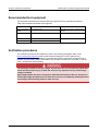
Introduction .......................................................................................................................... 8-1
Environmental conditions ..................................................................................................... 8-1
Warm-up period ................................................................................................................... 8-1
Recommended test equipment ............................................................................................ 8-2
Verification procedures ........................................................................................................ 8-2
DC voltage accuracy ................................................................................................................. 8-3
DC current limit accuracy .......................................................................................................... 8-5
Model 2290-5 5 kV Power Supply User's Manual
Troubleshooting ....................................................................................................... 9-1
Stuck buttons ....................................................................................................................... 9-1
Line power ............................................................................................................................ 9-1
Repeated trips ...................................................................................................................... 9-1
Incorrect rear-panel output voltage ...................................................................................... 9-2
Front-panel test .................................................................................................................... 9-2
Power-on reset ..................................................................................................................... 9-2
No high voltage .................................................................................................................... 9-2
Service ................................................................................................................................. 9-3
Table of Contents
Section 1
Introduction
In this section:
Welcome .................................................................................. 1-1
Extended warranty ................................................................... 1-1
Contact information .................................................................. 1-1
CD-ROM contents .................................................................... 1-2
Organization of manual ............................................................ 1-2
Features ................................................................................... 1-3
Unpacking and inspecting ........................................................ 1-3
Optional accessories ................................................................ 1-3
Front-panel familiarization ........................................................ 1-4
Rear-panel familiarization......................................................... 1-6
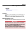
Welcome
Thank you for choosing a Keithley Instruments product. The Model 2290-5 5 kV power supply is
designed for use in the laboratory and for test applications. It also has excellent regulation and low
output voltage ripple. The digital displays provide accurate readings of voltage and current and also
provide for easy, precise setting of output values using digital entry of current and voltage values.
Output voltage can be set from the front panel, using a remote analog voltage, or over the standard
IEEE-488 interface. Voltage and current analog outputs are also available for remote monitoring and
analog control.
Extended warranty
Additional years of warranty coverage are available on many products. These valuable contracts
protect you from unbudgeted service expenses and provide additional years of protection at a fraction
of the price of a repair. Extended warranties are available on new and existing products. Contact your
local Keithley Instruments representative for details.
Contact information
If you have any questions after you review the information in this documentation, please contact your
local Keithley Instruments representative or call Keithley Instruments corporate headquarters (toll-free
inside the U.S. and Canada only) at 1-888-KEITHLEY (1-888-534-8453), or from outside the U.S. at
+1-440-248-0400. For worldwide contact numbers, visit the Keithley Instruments website
(http://www.keithley.com).
Section 1: Introduction
Model 2290-5 5 kV Power Supply User's Manual
CD-ROM contents
The Series 2290 Power Supply Product Information CD-ROM contains:
User's Manuals: Includes information about optional accessories, operation topics, remote operation,
performance verification, troubleshooting, and application examples that you can use as starting point
to create your own applications.
LabVIEW™ Driver and IVI Driver software: Instrument drivers are used to communicate with an
instrument and help to control it.
Organization of manual
Getting started: Front and rear panel familiarization, LED displays.
Safe connection: Configuration and test setup.
Basic operations: Set the voltage source, set the voltage trip limit, and set the current limit.
Remote operation: Remote interfaces and commands.
Status messages: Description of the Model 2290-5 status messages.
Errors: Error numbers with descriptions.
Typical applications: Detailed examples of how to use commands to accomplish certain test
applications.
Performance verification: Environmental conditions, test equipment, and verification procedures.
Troubleshooting: Description of commonly encountered issues and information on how to resolve
them.
1-2
2290-5-900-01 Rev. A/December 2013
Model 2290-5 5 kV Power Supply User's Manual
Section 1: Introduction
Features
The key features of the Model 2290-5 include:
•
•
•
•
•
•
•
High-voltage operation – Source voltages up to a maximum of 5 kilovolts (kV).
25 W power capability – Source currents up to 5 milliamps (mA) at 5 kV.
Ease of use – Digital displays and the keypad simplify setting the voltage and current parameters.
Programmable voltage limit – Voltage limit can be preset to ensure safe operation.
Programmable current limits – Current limit and trip point can be preset to prevent possible
equipment damage.
Output filter – Reduces output ripple and noise.
Monitor outputs – Provide 0 – 10 V signals that can be used to monitor the high-voltage output
and current.
•
External voltage control – Allows the high-voltage output value to be controlled with a 0 – 10 V
input signal.
•
Standard IEEE-488 interface – Allows the instrument to be remotely controlled by a personal
computer.
•
Safety interlock – Connections to an internal circuit that shuts down the high-voltage output when
an external circuit is opened. The external circuit would typically include a limit switch on a test
fixture door.
Unpacking and inspecting
Inspect for damage
Upon receiving the Model 2290-5, carefully unpack the unit, and inspect for any obvious signs of
physical damage that might have occurred during shipment. Notify the shipping agent of any damage
immediately.
Shipment contents
The following items are included with every Model 2290-5 order:
•
•
•
•
Model 2290-5 high voltage power supply
Model 2290-5 product information CD-ROM
AC line power cord
Model 2290-5 additional accessories, as ordered
2290-5-900-01 Rev. A/December 2013
1-3
Section 1: Introduction
Model 2290-5 5 kV Power Supply User's Manual
Optional accessories
The following optional accessories are available for use with the Model 2290-5:
Connecting cables and connectors
•
•
•
•
Model 2290-5-SHV – SHV plug to SHV plug cable; 3.05 meters (10 feet).
Model 2290-5-MHV – SHV plug to MHV male cable; 3.05 meters (10 feet).
Model 2290-INT-CABLE – 3-pin interlock connector to unterminated cable; 3.05 meters (10 feet).
Model 2290-5-SHVBH – SHV male bulkhead connector.
Rack mount kits
•
•
•
Model 2290-5-RMK-2 – double rack-mount kit; mounts two power supplies side-by-side.
Model 2290-5-RMK-1 – single rack-mount kit; mounts a single power supply.
Model 4299-7 – shelf rack-mount kit; mounts one or two power supplies.
Protection module
Model 2290-PM-200
The protection module is intended for use in applications where a device breakdown or other potential
failure could connect the high-voltage output of the Model 2290-5 or Model 2290-10 High Voltage
Power Supply to a lower voltage source-measure unit (SMU).
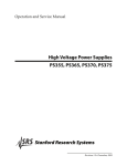
Front-panel familiarization
The Model 2290-5 front panel is shown below. Descriptions of the controls on the front panel follow
the figure.
Figure 1: Model 2290-5 front panel
1-4
2290-5-900-01 Rev. A/December 2013
Model 2290-5 5 kV Power Supply User's Manual
POWER button
HIGH VOLTAGE
enable switch
VOLTS LED display
Center LED display
mA LED display
SELECT, ENTER,
CLR (Clear) button
Numeric and cursor
buttons
STATUS indicators
Section 1: Introduction
Press the POWER button so that it is in the on position to turn the
instrument on. Press the POWER button so that it is in the off
position to turn it off.
This is a three position switch. In the OFF/RESET position, the high
voltage is off, and all trips are cleared. In this position, the high
voltage is locked off and cannot be turned on by computer control.
The ON position is a momentary-contact position and turns on the
high voltage for manual or rear panel analog control. Note that the
switch should be held in the ON position for at least a half second to
turn the high voltage on. In the middle position, the high voltage is
enabled and can be turned on by commands sent over the IEEE-488
bus. The ON LED above the switch indicates that the high voltage is
on; the yellow TRIP LED indicates a trip has occurred.
Displays the output voltage.
Displays the value of the parameter that is entered or adjusted,
including Error and status messages that may occur.
Displays the output current.
The SELECT button is used to choose which parameter is being
displayed in the center display. The ENTER button enters the
parameter shown in the center display. The CLR (clear) button
erases the value in the center display and recalls the last value that
was entered.
All parameters are adjusted using the cursor or numeric buttons.
Three LEDs indicate the instrument's status. The LIMIT LED is on
when the unit is in current limit. The REM LED is on when the unit is
in remote, and the front panel is locked out. The FILTER LED is on
when one of the two available output filters is enabled.
RESET button
Reset mode determines how the instrument responds after a voltage
or current trip. There are two modes: MAN and AUTO. In MAN
(manual) mode the high voltage remains off after a trip and requires
that the operator manually turn it back on.
In AUTO (automatic) mode the unit waits until the output voltage has
fallen to 2% of its full-scale value and then turns the high voltage
back on. This feature is useful when dealing with loads that
occasionally short circuit, but recover after high voltage has been
removed.
FILTER buttons
The output filter, which may be used to reduce output ripple and
noise, is controlled with the FILTER, NO FILTER, FILTER 1, and
FILTER 2 buttons.
GPIB ADDR buttons The GPIB address buttons set the GPIB primary address.
LOCAL button
The LOCAL button takes the instrument out of remote and restores
operation of other front panel controls.
STO and RCL
STO (store) and RCL (recall) allow up to nine complete instrument
settings to be saved in nonvolatile memory. RCL 0 recalls the default
buttons
settings.
2290-5-900-01 Rev. A/December 2013
1-5
Section 1: Introduction
Model 2290-5 5 kV Power Supply User's Manual
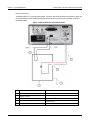
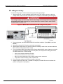
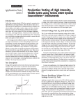
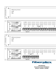
Rear-panel familiarization
The Model 2290-5 rear panel is shown below. Descriptions of the controls on the rear panel follow the
figure.
Figure 2: Model 2290-5 rear panel
Power entry
HIGH VOLTAGE output
port
Analog I/O
IEEE-488 STD PORT
INTERLOCK port
1-6
The power entry module contains the line fuse, the line voltage selection,
and includes filtering to block high-frequency noise from entering or exiting
the unit. Refer to the Safely connect to instruments topic for instructions on
selecting the correct line voltage and fuse.
The HIGH VOLTAGE output port is an SHV male port that connects the
Model 2290-5 source output to external equipment. SHV-to-SHV and SHVto-MHV mated high voltage cables are available.
The SET/MON and I MON BNC jacks provide voltage and current monitor
signals, or an external voltage control input and current monitor, depending
upon the setting of the VOLTAGE select switch. If the switch is in the MON
(monitor) position, the front panel controls the voltage. If the switch is in the
SET position, the rear panel analog voltage will control the output voltage
When the VOLTAGE select switch is in the MON (monitor) position, both
jacks are 0 to +10 V outputs corresponding to 0 to full scale. For example, if
the voltage source output is 2 kV, the SET/MON jack output voltage will be 4
V.
The 24-pin IEEE-488 (GPIB) port allows computer control of the Model
2290-5.
The contacts of the interlock port allow an external limit switch in the
connector path. The circuit must be engaged to allow high-voltage output.
2290-5-900-01 Rev. A/December 2013
Model 2290-5 5 kV Power Supply User's Manual
Section 1: Introduction
Line cord
The Model 2290-5 uses a detachable, three-wire power cord for connection to the power source and
to a safety earth ground through a grounded AC outlet. Only use the power cord that's provided with
your instrument, or an equivalent adequately rated power cord.
The exposed metal parts of the instrument are connected to the outlet ground through the
line cord to provide protection against electrical shock. Always use an AC outlet that has a
properly connected safety ground.
Connect to other instruments
The rear panel SET/MON and I MON BNC jack shields are connected to chassis ground and the AC
power source ground using the power cord. Do not apply any voltage to the shields. The HIGH
VOLTAGE SHV port is also connected to chassis ground and cannot be floated above ground.
This unit contains hazardous voltages. Be absolutely certain that the high voltage is
completely discharged before removing or connecting the high-voltage cable. High-voltage
cables can store charge if they are disconnected from the supply while high voltage is
turned on, and can cause personal injury or death if not handled properly. Use only
connecting cables with a rated working voltage of 5 kV or higher (see the Optional
accessories section for more information).
Do not connect the high-voltage output to exposed circuitry. And load connected to the
high-voltage output should be enclosed in a metal shield that is connected to safety earth
ground using #18 AWG or larger wire.
If the instrument is used in a manner not specified by Keithley Instruments, the protection
provided by the equipment may be impaired.
2290-5-900-01 Rev. A/December 2013
1-7
Section 2
Safe configuration and test setup
In this section:
Introduction .............................................................................. 2-1
High voltage safety precautions ............................................... 2-1
Safely connect to instruments .................................................. 2-2
Interlock circuit ......................................................................... 2-2
Introduction
The Model 2290-5 can generate hazardous voltages. It is intended for use with a test fixture or in a
test system that has safety mechanisms in place to prevent an operator from accessing these
voltages.
This section describes how to use the Model 2290-5 to test a device with a custom test fixture or
system.
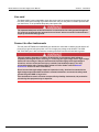
High voltage safety precautions
Make sure that you read and observe the following high voltage safety precautions before operating
the Model 2290-5.
The Model 2290-5 is capable of sourcing hazardous live high voltages that can cause
personal injury or death due to electric shock. This unit should be used only by qualified
personnel who recognize the dangers of high voltages.
Make certain that the source is turned off and that high voltage is completely discharged
before removing the high-voltage cable. High-voltage cables can store charge if they are
disconnected from the supply while the high voltage is on. The charge on the cable can
cause injury or damage even after the cable is disconnected from the unit.
The Model 2290-5 is provided with an interlock circuit that must be engaged to allow high
voltage output. The interlock helps facilitate safe operation of the equipment in a test
system. Bypassing the interlock could expose the operator to hazardous voltages that could
result in personal injury or death.
Section 2: Safe configuration and test setup
Model 2290-5 5 kV Power Supply User's Manual
Safely connect to instruments
Line voltage selection
There are three versions of the Model 2290-5 to allow operation from a 100, 120, 220, or 240 V
nominal AC power source with a line frequency of 50 or 60 Hz. Before connecting the power cord to a
power source, verify that the line voltage selector card, located in the rear panel fuse holder, is set for
the correct AC line voltage.
The following table indicates the three versions of the Model 2290-5 5 kV power supply and their
respective line voltage:
Model
Nominal voltage
2290-5
2290E-5
2290J-5
120 V AC
220/240 V AC
100 V AC
This instrument may be damaged if operated with the line voltage selector set for the wrong AC line
voltage, or if the wrong fuse is installed.
Line fuse
Verify that the correct line fuse is installed before connecting the line cord as follows:
Model
Line voltage
Fuse type
Keithley fuse
part number
2290-5
2290J-5
120 V AC
100 VAC
1 A, 250 V, 3 AG, Slow Blow
FU-10
2290E-5
220/240 V AC
1/2 A, 250 V, 3 AG, Slow
Blow
FU-4
Interlock circuit
An interlock circuit is provided on the rear panel of the instrument. This circuit must be engaged to
allow the Model 2290-5 to produce output voltages. When the safety interlock signal is engaged, all
voltage ranges of the instrument are available. However, when the safety interlock signal is
disengaged, the output voltage is turned off.
The Model 2290-5 is provided with an interlock circuit that must be engaged to allow high
voltage output. The interlock helps facilitate safe operation of the equipment in a test
system. Bypassing the interlock could expose the operator to hazardous voltages that could
result in personal injury or death.
2-2
2290-5-900-01 Rev. A/December 2013
Model 2290-5 5 kV Power Supply User's Manual
Section 2: Safe configuration and test setup
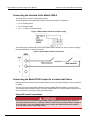
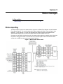
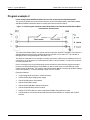
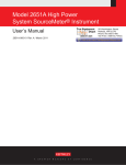
Connecting the interlock of the Model 2290-5
The interlock pins control the high-voltage supply.
The pin locations and connections are shown in the following figure. The pins are:
•
•
•
Pin 3: Chassis ground
Pin 2: Interlock enable
Pin 1: +5 V DC out (current limited)
Figure 3: Model 2290-5 Interlock connector wiring
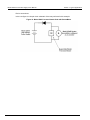
The following figure shows how to connect the Model 2290-5 internal 5 V source in order to engage
the external interlock (or interlocks) circuits:
Figure 4: Model 2290-5 Internal 5 kV source
Connecting the Model 2290-5 output to a custom test fixture
Keithley Instruments offers several accessories that can help you when building a custom test fixture
or system.
You can use a high-voltage SHV bulkhead connector (Model 2290-5-SHVBH) on your test fixture.
The following sections show you how to connect a Model 2290-5 to a custom fixture and also how to
make connections to the device inside the custom fixture.
Using SHV coaxial connections
If you need to convert from safe high-voltage (SHV) to another connector type, be sure to
only adapt SHV connectors to connectors that are rated to the maximum possible voltage in
your test setup. If you use adapters that are not rated to the maximum possible voltage in
your test setup, electric shock may result.
2290-5-900-01 Rev. A/December 2013
2-3
Section 2: Safe configuration and test setup
Model 2290-5 5 kV Power Supply User's Manual
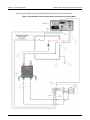
Device connections
Equipment used in the next figure:
•
•
•
•
1 high-voltage diode enclosed in a safe test fixture
1 Model 2290-5 high-voltage power supply
1 Model 2290-5-SHV cable
1 Model 2290-5-SHVBH bulkhead connector
The next figure shows a test configuration using the Model 2290-5 power supply with a safe interlock
test enclosure circuit:
Figure 5: Model 2290-5 high-voltage output connections
2-4
2290-5-900-01 Rev. A/December 2013
Model 2290-5 5 kV Power Supply User's Manual
Item
Description
1
Model 2290-5-SHV high-voltage cable
2
3
4
Model 2290-5-SHVBH high-voltage male
bulkhead connector
Test fixture protective earth (safety ground)
Test fixture interlocked metal safety enclosure
5
Test fixture lid interlock switch connection
2290-5-900-01 Rev. A/December 2013
Section 2: Safe configuration and test setup
Notes
A safety enclosure with an interlock that has a normally
open (NO) switch.
Connect pin 1 (+5 V DC out) and pin 2 (interlock).
2-5
Section 3
Basic operations
In this section:
Numeric and cursor buttons ..................................................... 3-1
Select, Enter, Clear .................................................................. 3-1
Output filter............................................................................... 3-2
Store and recall ........................................................................ 3-3
Analog programming and monitor ............................................ 3-4
Set output voltage .................................................................... 3-6
Turn output on .......................................................................... 3-6
Set voltage limit ........................................................................ 3-6
Set current limit ........................................................................ 3-7
Set current trip.......................................................................... 3-7
Numeric and cursor buttons
All parameters are adjusted using the cursor or numeric buttons. When using the cursors, the
adjusted digit in the center display will flash. When using direct numerical entry, press the number
and decimal point buttons until the desired value appears on the center display. Note that the current
is specified in mA.
The cursor buttons are used to adjust parameters:
•
•
•
•
Up arrow increments the digit
Down arrow decrements the digit
Left arrow cursor selects and moves the digit to the left
Right arrow cursor selects and moves the digit to the right
Select, Enter, Clear
To adjust a value, press the SELECT button until the appropriate LED is lit (for example, the
VOLTAGE LEDs SET or LIMIT). While the value is changing, the appropriate LED will flash indicating
that the value in the center display is not the present unit setting. If an incorrect value is entered,
press CLR (clear) to start over. When the desired value is in the center display, press the ENTER
button to update the unit's actual setting, and the LED will stop flashing.
Section 3: Basic operations
Model 2290-5 5 kV Power Supply User's Manual
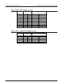
Output filter
The Model 2290-5 employs a switchable output filter for low noise performance. If higher slew rate or
output power is required, the filter can be disabled. When the filter is enabled, the unit can reach
either maximum voltage or maximum current but not both simultaneously. The filter has three
possible settings: Filter Disabled (Filter 0); Filter Enabled, High Current (Filter 1); and Filter Enabled,
High Voltage (Filter 2).
The output filter determines the voltage and current limits, as well as the ripple and noise
performance of the unit. Note that the noise reduction characteristics for the two filters are identical,
but other factors such as rise and discharge times virtually depend on the selected filter (see
specifications). See the specifications for information on ripple and noise for the different filter
settings. The voltage and current limits for the different filter settings are listed in the next table.
Filter mode
Voltage limit
Current limit
Current trip
Filter out (Filter 0)
High Current Filter (Filter 1)
High Voltage Filter (Filter 2)
5000 VDC
3000 VDC
5000 VDC
5.25 mA
5.25 mA
3.25 mA
5.25 mA
5.25 mA
3.25 mA
It is recommended that you turn off the output before changing the filter. If the filter is changed while
the high voltage is on, the unit will turn off the high voltage and wait until the voltage has dropped
below 100 VDC before switching the filter. This is done to minimize stress on the filter components.
During this time, the HIGH VOLTAGE ON switch is disabled. If the filter is changed while the high
voltage is off, it will switch immediately.
To display and change the present filter value:
1. Press the FILTER button to display the current filter selection in the center display.
2. Press FILTER 1 or FILTER 2 at the FIL display prompt (the associated FILTER LED will turn on
to indicate that the filter is enabled).
3. Enter a new filter value (enter the value), then press the ENTER button.
4. To turn off filtering, press FILTER then NO FILTER followed by ENTER.
If an illegal value is entered, the unit will display Err2 (illegal parameter entered). Use the CLR button
to clear any error messages.
3-2
2290-5-900-01 Rev. A/December 2013
Model 2290-5 5 kV Power Supply User's Manual
Section 3: Basic operations
Store and recall
STO (store) and RCL (recall) allow up to nine complete instrument setups to be saved in nonvolatile
memory and later recalled.
To store a setup:
1.
2.
3.
4.
Program the various instrument operating modes to be stored.
Press the STO button.
Press a number (1 to 9) to select the desired storage location.
Press the ENTER button to complete the storage process.
To recall a setup:
1. Press the RCL button.
2. Press the number button (1 to 9) for the configuration to be recalled. (RCL 0 returns the
instrument to the factory default setup.)
3. Press the ENTER button.
Whenever a setup is recalled, the high voltage is turned off for safety.
If an Err3 (recall error) occurs, the stored setup was lost due to a memory error and must be stored
again using the STO button.
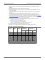
The factory default setup can be recalled by pressing the CLR button while turning on the power or by
recalling setup 0 (RCL 0). The default setup is also recalled after a power-on memory error (Err 1).
The next table lists the factory default setup.
2290-5-900-01 Rev. A/December 2013
Mode
Default setting
Output voltage
Voltage limit
Current limit
Current trip
Reset mode
High voltage
GPIB address
Filter
0V
5000 V
5.25 mA
5.25 mA
MAN
OFF
14
OFF
3-3
Section 3: Basic operations
Model 2290-5 5 kV Power Supply User's Manual
Analog programming and monitor
The rear panel VOLTAGE select switch determines whether the output voltage is set from the front
panel or from the rear panel SET/MON input. If the switch is in the MON (monitor) position, use the
front panel controls. If the switch is in the SET position, use the rear panel analog voltage to control
the output voltage.
When the VOLTAGE switch is in the SET position, the I MON jack remains an output signal, the
SET/MON jack becomes an input signal and sets the high voltage source value over the same range
as the control voltage input. For example, a 2 V analog voltage input results in a 1 kV source output
voltage. When the switch is in the SET position, the REAR LED on the front panel is lit, indicating that
high voltage is under analog control and cannot be adjusted using the front panel buttons. All signals
are positive voltages.
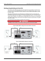
The next two figures show examples of analog output connections.
The BNC jack outer shells are connected to chassis ground and cannot be floated.
Figure 6: Model 2290-5 voltage and current monitor connections
Figure 7: Model 2290-5 Voltage set connections
3-4
2290-5-900-01 Rev. A/December 2013
Model 2290-5 5 kV Power Supply User's Manual
Section 3: Basic operations
When the VOLTAGE switch is in the SET position, the REAR (rear panel) LED is on, and the output
voltage is controlled by the rear panel signal and displayed on the center display when in the
VOLTAGE SET mode. The voltage limit is still active, and the unit does not allow the rear panel
voltage to set the output value above the voltage limit.
If the VOLTAGE switch position is changed while the high voltage is on, the unit will turn off the high
voltage.
Voltage Monitor: When the VOLTAGE switch is in the MON position, the SET/MON jack is a monitor
output providing 0 to +10V for 0 to full-scale output. The next table lists the voltage monitor examples.
Output voltage Analog monitor examples
1 kV
2V
3.5 kV
5 kV
7V
10 V
2.5 kV
5V
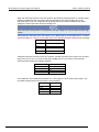
Voltage Set: When the switch is in the SET position, this BNC jack becomes an input over the same
range. An input of 0 V to +10 V will set the output voltage from 0 V to full scale. The next table
summarizes the analog input voltage examples.
Analog input voltage
High voltage output
2V
5V
6V
10 V
1 kV
2.5 kV
3 kV
5 kV
Current Monitor: The I MON jack provides a 0 to +10V signal for 0 to full-scale current output. The
next table summarizes the current monitor output examples.
2290-5-900-01 Rev. A/December 2013
Current output
Current monitor
1 mA
2.5 mA
3.5 mA
5 mA
2V
5V
7V
10 V
3-5
Section 3: Basic operations
Model 2290-5 5 kV Power Supply User's Manual
Set output voltage
To manually set the output voltage, with the high voltage on or off (refer to the Front-panel
familiarization graphic for more information):
1. Press the SELECT button until the VOLTAGE SET LED is on. The present voltage setting will
appear on the center display.
2. To change the voltage setting, enter the desired voltage using either the numeric or cursor
buttons.
3. After the new value has been entered into the center display, press ENTER to update the output
voltage.
The VOLTAGE SET LED will flash until ENTER or CLR is pressed to remind you that the displayed
value is not the actual programmed value.
If an Err2 message appears (illegal parameter entered), check the voltage limit to see that it is
greater than or equal to the desired set voltage. Use the CLR button to clear any error message (see
the Set voltage limit topic for more information).
If the REAR LED is on, the high voltage is programmed from the voltage applied to the analog input
on the rear panel. In this mode, the high voltage cannot be programmed from the front panel, and the
center display will show the actual output voltage in the VOLTAGE SET mode.
If you want to set the output voltage remotely, refer to Voltage set (see VSET(?) <n>). To set the
output voltage using the rear panel analog input, refer to Analog programming and monitor.
Turn output on
Once you have set the voltage limit, you must press the HIGH VOLTAGE enable switch (see Set
voltage limit for more information).
The switch should be held in the ON position for at least a half second to turn the high voltage on. If
the interlock is open, an iloc error message appears on the center display, the voltage will be 0,
and the yellow TRIP LED indicates that a trip has occurred (see Front-panel familiarization for more
information).
Set voltage limit
The voltage limit is a protection feature intended to prevent the output voltage from being set too high
or from overshooting because of large load changes. The output voltage cannot be set higher than
the voltage limit. In addition, if the output voltage ever exceeds the programmed limit by more than
10% of full scale, the trip point is reached, and the high voltage is disabled. In this case, a VTRP
(voltage trip) message appears on the center display.
It is not necessary to clear the trip before turning the high voltage back on. If it is necessary to
change a parameter before turning the high voltage back on, pressing CLR or placing the high
voltage switch in the off position will clear the trip.
3-6
2290-5-900-01 Rev. A/December 2013
Model 2290-5 5 kV Power Supply User's Manual
Section 3: Basic operations
Set the voltage limit as follows:
1. Press the SELECT button until the VOLTAGE LIMIT LED is lit. The present value of the voltage
limit is shown on the center display.
2. Change the limit value using either the numeric or cursor buttons.
3. Press ENTER to update the actual limit value.
If an Err2 message appears (illegal parameter entered), check to see that the output voltage is less
than or equal to the new desired voltage limit.
Set current limit
The power supply output current is clamped at the current limit. If the current limit is reached, the
output voltage may not equal its programmed value. When the unit is current limited, the STATUS
LIMIT LED is on.
Set the current limit as follows:
1. Press the SELECT button until the mA LIMIT LED is on. The present value of the current limit is
shown on the center display.
2. Change the limit value using either the numeric or cursor buttons.
3. Press ENTER to update the actual limit value.
Set current trip
The current trip shuts off the high voltage when the output current exceeds the trip value. The current
trip value is set in the same manner as the voltage and current limits. After a current trip occurs, the
ITRP (current trip) message will appear on the middle display. Current trips are cleared in the same
fashion as voltage trips.
Set the current trip as follows:
1. Press the SELECT button until the mA TRIP LED is on. The present value of the current trip is
displayed in the center window.
2. Change the limit value using either the numeric or cursor buttons.
3. Press ENTER to update the actual trip value.
2290-5-900-01 Rev. A/December 2013
3-7
Section 4
Remote operation
In this section:
Introduction .............................................................................. 4-1
Command syntax ..................................................................... 4-3
Remote commands .................................................................. 4-4
Introduction
This section contains detailed information on remotely programming the Model 2290-5 over the IEEE488 (GPIB) interface. Any computer that supports the IEEE-488 bus may be used to program the
instrument. The Model 2290-5 supports the IEEE-488.1 (1978) interface standard, as well as the
required common commands of the IEEE-488.2 (1987) standard.
The cabling distance between the controller and instrument hub with GPIB is limited to 9 meters (30
feet). In a system connected with GPIB, you can have 15 instruments attached to each controller.
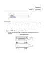
Connect GPIB cables to your instrument
To connect an instrument to the GPIB, use a cable equipped with standard GPIB connectors, as
shown below.
Figure 8: GPIB Connector
Section 4: Remote operation
Model 2290-5 5 kV Power Supply User's Manual
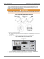
To make a parallel connection to the instrument, stack the connectors. Each connector has two
screws to ensure that connections remain secure. The figure below shows a typical connection
diagram for a test system with multiple instrument .
To avoid possible mechanical damage, stack no more than three connectors on any one instrument.
To minimize interference caused by electromagnetic radiation, use only shielded GPIB cables.
Contact Keithley Instruments for shielded cables.
Figure 9: Model 2290-10 GPIB example connections
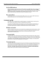
To connect the instrument to the GPIB:
1. Align the cable connector with the port on the rear panel. The location of the port is shown in the
following figure.
2. Attach the connector. Tighten the screws securely but do not overtighten them.
Figure 10: Model 2290-5 rear panel GPIB location
3. Connect any additional connectors from other instruments, as required for your application.
4. Ensure the other end of the cable is properly connected to the controller.
4-2
2290-5-900-01 Rev. A/December 2013
Model 2290-5 5 kV Power Supply User's Manual
Section 4: Remote operation
Set the GPIB address
Before attempting to communicate with the Model 2290-5 over the IEEE-488 interface, make sure the
instrument's primary address is set correctly. To enter the GPIB address mode, press both GPIB
ADDR buttons simultaneously and then increment or decrement the address as required using the up
and down arrow buttons. The allowable primary address range is from 0 to 30. Be sure to avoid
address conflicts with other instruments on the bus, including the controller.
Bus connections
With the power off, connect the Model 2290-5 GPIB connector to the computer IEEE-488 interface.
Shielded GPIB cables such as the Keithley Model 7007 are recommended.
Command syntax
Commands sent to the Model 2290-5 use ASCII characters. Commands may be in either upper or
lower case and may contain any number of embedded space characters.
A command to the Model 2290-5 must be followed by a command terminator. The terminator is a
linefeed (<LF>) or EOI. No command processing occurs until a command terminator is received.
Commands beginning with an asterisk (*) are IEEE-488.2 defined common commands.
Multiple commands
Multiple commands may be sent on one command line by separating them with semicolons (;). When
several commands are included on the same line, the entire line is parsed and executed before any
other device action proceeds. This method allows command synchronization using the
synchronization command (*WAI).
Command buffer
The Model 2290-5 has a 256-character input buffer and processes commands in the order received.
Therefore, it is not necessary to wait between commands. If the buffer becomes full, the Model 22905 will hold off bus handshaking until commands are processed. Similarly, the unit has a 256-character
output buffer to store output data until the host computer is ready for reception. If the output buffer
becomes full, it is cleared, and an appropriate error is reported.
Command queries
The present value of a particular parameter may be determined by querying the Model 2290-5 for its
value. A query is formed by appending a question mark (?) to the command and omitting the desired
parameter from the command. If multiple queries are sent on one command line (separated by
semicolons), responses will be returned in a single line with the individual responses separated by
semicolons. The default response terminator is a linefeed (<LF>) plus EOI. All commands return
integer results except as noted in individual command descriptions.
2290-5-900-01 Rev. A/December 2013
4-3
Section 4: Remote operation
Model 2290-5 5 kV Power Supply User's Manual
Command examples
Command
Description
VSET 1.0E3
VSET?
*IDN?
VSET 100.0;VSET?
Sets the voltage to 1000 V.
Queries the voltage setting.
Queries the device identification.
Sets the voltage to 100 V and queries the voltage.
Remote commands
The following Model 2290-5 commands are divided by the type of command: Output control, Setting
control, Interface control, and Status reporting. Note that multiple parameters are separated by
commas. Commands with queries are followed by a question mark in parentheses (?). Commands
that have only a query include a “?”. Commands that cannot be queried have no question mark.
Brackets [ ] indicate the parameter is optional. An asterisk (*) preceding the command indicates IEEE488.2 common commands.
Parentheses shown in command descriptions indicate only that a query form is available. Do not
include parentheses in commands.
Output control commands
HVOF
The HVOF command turns off the high voltage output.
HVON
The HVON command turns on the high voltage provided that the front panel HIGH VOLTAGE switch
is not in the OFF position. If the switch is in the OFF position, the high voltage is left off, and an
execution error is reported. This command also automatically clears any voltage or current trips.
An Err6 (syntax error over GPIB) may appear when sending this command. To avoid this situation,
insert a *WAI (wait command) before HVON. The command string *WAI;HVON is valid.
IOUT?
The IOUT? query returns the value of the actual output current. This value is the same as that shown
on the front panel mA display.
As with the front panel display, this value takes about one second to stabilize after a change in
current.
4-4
2290-5-900-01 Rev. A/December 2013
Model 2290-5 5 kV Power Supply User's Manual
Section 4: Remote operation
VOUT?
The VOUT? query returns the actual output voltage. This value is the same as that shown on the front
panel VOLTS display. The value returned is a floating-point number and includes the positive sign of
the output voltage.
As with the front panel voltage display, this value takes about one second to stabilize after a change
in voltage.
Setting control commands
*RCL <n>
The *RCL (Recall) command recalls stored configuration setting <n>, where <n> ranges from 0 to 9.
Setting 0 recalls the default settings. If the stored setting is corrupted, an error is returned.
Example:
*RCL 0
Recall default setting
*SAV <n>
The *SAV (Save) command stores the present instrument setup as setting <n>, where <n> ranges
from 1 to 9.
Example:
*SAV 3
Save setting #3
ILIM(?) <n>
The ILIM command sets the value of the current limit to <n>, where <n> is a floating-point value in
amperes. The ILIM? query returns the current limit setting.
Example:
ILIM 1E-3
Set 1 mA current limit
Default value: 5.25 mA
ITRP(?) <n>
The ITRP command sets the value of the current trip to <n>, where <n> is a floating-point value in
amperes. The ITRP? query returns the current trip setting.
Example:
ITRP 1E-3
Set 1mA trip current
Default value: 5.25 mA
2290-5-900-01 Rev. A/December 2013
4-5
Section 4: Remote operation
Model 2290-5 5 kV Power Supply User's Manual
SMOD?
The SMOD? query returns the VSET setting mode. A returned value of 0 indicates that the voltage
value is controlled by the front panel or bus setting, while the value 1 indicates that the output is
controlled by the rear panel SET/MON voltage control input. Note that the setting mode may only be
changed by setting the rear panel VOLTAGE switch.
TCLR
The TCLR command clears any voltage or current trips.
TMOD(?) <n>
The TMOD command sets the trip reset mode. The value <n> = 0 sets manual trip reset, while the
value <n> = 1 sets the trip reset mode to automatic.
VLIM(?) <n>
The VLIM command sets the value of the voltage limit to <n>, where <n> is in volts. The VLIM?
query returns the present limit setting. As with front panel control, the VLIM value must be greater
than or equal to the VSET value, or an execution error will occur.
Example:
VLIM 500
Set 500 V voltage limit
Default value: 5000 V
VSET(?) <n>
The VSET command sets the voltage output level to <n>. If rear panel control is enabled, an error is
returned. The value <n> is in volts. The VSET? query returns the current VSET value. As with front
panel control, the VSET value must be less than or equal to the VLIM value, or an execution error
will occur.
Example:
VSET 2500
Set output to 2.5 kV
Default value: 0 V
4-6
2290-5-900-01 Rev. A/December 2013
Model 2290-5 5 kV Power Supply User's Manual
Section 4: Remote operation
FILT(?) <n>
The FILT command controls the output filter, which is useful for reducing output ripple and noise.
When <n> = 0 the output filter is disabled, while <n> = 1 and <n> = 2 enable Filter 1 and Filter 2,
respectively. The FILT? query returns the state of the filter.
Example:
FILT 1
Enable Filter 1
Default value: 0
When the filter is changed, the high voltage is turned off. The unit does not actually change the filter
until the high voltage has dropped below 100 VDC. If the high voltage is turned on remotely while the
filter is in the process of changing, an error will result. So if the commands FILT 1;HVON are sent,
an Err7 (illegal GPIB command) will appear. To avoid this situation, insert a *WAI (wait command)
between the two. The command string FILT 1;*WAI;HVON is valid.
For more information about the output filter, see the Output filter topic.
Interface control commands
*RST
The *RST (Reset) common command resets the Model 2290-5 to its default configuration. This
command performs the same function as holding down the front panel CLR button at power-on.
*IDN?
The *IDN? (Identification) common query returns the Model 2290-5 device configuration. The
response string is in the format:
KEITHLEY INSTRUMENTS INC., MODEL 2290-5, <serial_number>, <version_number>
Where:
2290-5 is the model number.
serial_number is the serial number of the particular unit.
version_number is the 3-digit firmware version level.
*WAI
The *WAI common command is a synchronization command that halts further command processing
until all present commands are complete. For example, the commands FILT 1;*WAI;HVON will
change the output filter setting, wait until the operation is complete, and turn the high voltage back on.
Status reporting commands
The following commands control various status reporting aspects.
*CLS
The *CLS (Clear Status) common command clears all status registers.
2290-5-900-01 Rev. A/December 2013
4-7
Section 4: Remote operation
Model 2290-5 5 kV Power Supply User's Manual
*ESE(?) <n>
The *ESE common command sets the Standard Event Status Enable Register. The parameter <n> is
the decimal value that programs the enable register.
Example:
*ESE 12
Set bits 2 and 3
*ESR? [<n>]
The *ESR? common query reads the value of the Standard Event Status Register. If the parameter
<n> is present, the value of bit <n> is returned. Reading this register without specifying <n> will clear
the register, but reading bit <n> will clear only bit <n>. The range of <n> is 0 to 7.
Example:
ESR? 2
Request and clear bit 2
*PSC(?) <n>
The *PSC (Power-on Status Clear) common command sets the value of the power-on status clear bit.
If <n> = 1, the power-on status clear bit is set, and all status registers and enable registers are
cleared on power-up. If <n> = 0, the bit is cleared, and the status enable registers maintain their
values at power-down. This feature allows the generation of a service request at power-up.
Example:
*PSC 1
Set power-on status clear bit
*SRE(?) <n>
The *SRE (Service Request Enable) common command sets the value of the Service Request
Enable Register. The parameter <n> is the decimal value representing the register bits to be set.
Example:
*SRE 3
Set bits 0 and 1
*STB? [<n>]
The *STB? (Status Byte) common query reads the value of the Status Byte Register. If the parameter
<n> is included, the value of bit <n> is returned. Reading this register has no effect on its value; it
only represents the summary of the other status registers. The range of <n> is 0 to 7.
Example:
4-8
*STB? 1
Request bit 1 status
2290-5-900-01 Rev. A/December 2013
Section 5
Status messages
In this section:
Status reporting ........................................................................ 5-1
Status reporting
The Model 2290-5 reports on its status with two registers: the Status Byte Register and the Standard
Event Status Register. The overall configuration of these registers is shown in the next figure. Note
that bits 0, 1, and 8 through 15 of both the Standard Event Status Register and Standard Event
Status Enable Register are not used in the Model 2290-5 and are always set to zero.
On power-up, the 2290-5 will either clear all of its status enable registers or maintain them in the state
they were in during power-down. The action taken is controlled by the *PSC command and allows
events such as SRQ on power-up to be generated if desired.
Figure 11: Model 2290-5 Status model
Section 5: Status messages
Model 2290-5 5 kV Power Supply User's Manual
Status byte register
The next table summarizes bits in the Status Byte, which may be read with the *STB? query or with
the serial polling sequence. The Model 2290-5 will generate a service request (SRQ) whenever one
of these bits is set and the corresponding bit in the Service Request Enable Register is set, except for
bit 6, the RQS/MSS bit. (Use the *SRE command and the decimal bit value in the table to set Service
Request Enable Register bits.) Note that any given status condition will produce only one SRQ even if
that condition is never cleared.
Table: Status byte
Bit
Decimal
value
Name
Description
0
1
Stable
1
2
1
Indicates that the VSET or ILIM value is stable. The function depends on whether the
Model 2290-5 is in current limit or constant voltage mode.
Indicates that a voltage trip has occurred.
2
4
1
Indicates that a current trip has occurred.
3
8
1
Indicates that a current limit condition has occurred.
4
5
6
16
32
64
MAV
ESB
Indicates message available in the GPIB output queue.
Indicates that an unmasked bit in the Standard Event Status Register has been set.
Request for Service/Master Summary Status.
V trip
I trip
I lim
2
RQS/MSS
7
128
HV on
Indicates that the high voltage is on.
Note: SRQ may be enabled for corresponding condition by sending *SRE with decimal value of bit (except bit 6). For
example, *SRE 4 enables SRQ on current trip.
1
The V trip, I trip, and I lim bits are latched bits. They are set on the occurrence of the appropriate event and will remain set
until either the status byte is read or the *CLS command is sent. Latching allows you to detect if a trip or limit condition has
ever occurred.
2
Request for Service bit in serial poll byte. Master Summary Status bit in *STB? response.
Standard event status register
The next table summarizes the bits in the Standard Event Status Register, which can be read using
the *ESR? query. This status register is defined by the IEEE-488.2 standard and is used primarily to
report errors in commands received over the GPIB. When the bits in this register are latched, they
stay latched and are cleared by reading them, or by sending the *CLS command. If a bit in the
Standard Event Status Register is latched and the corresponding bit in the Standard Event Status
Enable Register (programmed with *ESE) is also latched, the ESB bit in the Status Byte Register is
latched.
5-2
2290-5-900-01 Rev. A/December 2013
Model 2290-5 5 kV Power Supply User's Manual
Section 5: Status messages
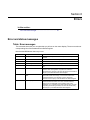
Table: Standard event status register
Bit
Decimal value
0
1
2
3
4
1
2
4
8
16
Name
Description
Unused
Unused
Query Error Set by an output queue overflow.
Recall Error Set if a stored configuration setting is corrupt.
Set by an out-of-range parameter, or non-completion of a command due to a
Execution
condition such as an overload.
Command
5
32
Set by a command syntax error or unrecognized command.
Error
6
64
URQ
Set by any button press.
7
128
PON
Set by power-on.
Note: Set ESB bit in Status Byte Register by sending *ESE command with desired condition. For example, *ESE 16 sets ESB
on execution error.
2290-5-900-01 Rev. A/December 2013
5-3
Section 6
Errors
In this section:
Error and status messages ...................................................... 6-1
Error and status messages
Table: Error messages
The next table shows the error numbers that you will see on the center display. These errors also set
corresponding bits of the Standard Event Status Register.
Note that the CLR button clears any errors.
Error number
Description
Comments
Err1
Memory Error
Err2
Err3
Err4
Err5
Illegal Parameter Entered
Stored Value Recall Error
Illegal Storage Address
No GPIB Interface
Err6
Syntax error over GPIB
Err7
Illegal parameter sent over
GPIB
Err8
GPIB Output queue full
Power-on memory error of the last setup. Default setup is
recalled.
Parameter entered is out of range.
The stored setup (from STO and RCL) was lost.
STO 0 is reserved for default settings.
GPIB interface not detected, and the GPIB address cannot be
set.
Invalid command. Err6 indicates the command had an error in
syntax or was unrecognizable. A syntax error could be a
misspelling of a command. This error will set the Command Error
bit (bit 5) of the Standard Event Status Register.
Parameter programmed is out of range. Err7 indicates a
parameter was set out of range, or a command could not be
completed because of an overload. This error will set the
Execution Error bit (bit 4) of the Standard Event Status Register.
Output buffer overflowed. Err8 indicates the output queue
overflowed and was cleared. This error could be caused by
querying the unit repeatedly and not reading out all of the
characters, or by a problem at the GPIB controller (the unit that's
requesting and receiving the data). This error will set the Query
Error bit (bit 2) of the Standard Event Status Register.
Section 6: Errors
Model 2290-5 5 kV Power Supply User's Manual
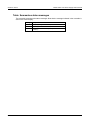
Table: Summarizes status messages
The next table summarizes the status messages. Note that the message indicated in the next table is
seen on the center display.
6-2
Message
Description
VTRP
ITRP
PTRP
Voltage trip (voltage limit exceeded)
Current trip (current limit exceeded)
Primary trip (power transformer primary current limit
exceeded)
2290-5-900-01 Rev. A/December 2013
Section 7
Typical applications
In this section:
Introduction .............................................................................. 7-1
Program example 1 .................................................................. 7-1
Program example 2 .................................................................. 7-4
Introduction
This section is broken into two examples:
Example 1 demonstrates how to generate a basic linear voltage sweep with the Model 2290-5 to
reverse bias a high voltage diode and make leakage current measurements at each point of the
sweep.
Example 2 demonstrates basic interaction of the Model 2290-5 high voltage power supply with a
Model 263xB System SourceMeter. The Model 2290-5 is used to generate a basic linear voltage
sweep across the diode and the Model 263xB is used to make a leakage current measurement on the
diode.
Program example 1
Linear voltage sweep and current measurements with Model 2990-5
Equipment needed:
•
•
•
•
1 high-voltage diode enclosed in a safe test fixture
1 Model 2290-5 high voltage power supply
1 GPIB cable to connect the Model 2290-5 to a computer with a GPIB interface
Appropriate cabling to connect the Model 2290-5 to the test fixture
Section 7: Typical applications
Model 2290-5 5 kV Power Supply User's Manual
Device connections:
The Model 2290-5 is a unipolar power supply. Therefore, the diode should be connected so that it can
be reverse-biased, which means that the cathode should be connected to the HI output terminal of
the Model 2290-5.
Figure 12: Model 2290-5 reverse-biased diode
7-2
Item
Description
1
2
Model 2290-5-SHV high-voltage cable
Model 2290-5-SHVBH high-voltage male
bulkhead connector
3
4
Test fixture protective earth (safety ground)
Interlocked metal safety enclosure
5
Test fixture interlock switch connection
Notes
A safety enclosure with an interlock that has a normally
open (NO) switch.
Connect pin 1 (+5 V DC out) and pin 2 (interlock)
2290-5-900-01 Rev. A/December 2013
Model 2290-5 5 kV Power Supply User's Manual
Section 7: Typical applications
Example program code
The following code was created and tested using the Python programming language using the
pyVISA module. To learn more about Python, go to www.python.org.
The example python program code below can be copied and pasted for your testing purposes,
however, the code must match to include the indents of specific lines.
# Import pyVisa and time modules into the Python environment
import visa
import time
# Open a VISA session with the 2290 at GPIB address 14
ki2290 = visa.instrument("GPIB::14")
# Reset and clear the status of the 2290
ki2290.write("*RST")
ki2290.write("*CLS")
ki2290.write("*RCL 0")
# Define sweep variables for the programmed output voltage and
# measured current readings
voltage = 0
currReading = ""
currRdgList = []
# Turn on the output of the 2290
time.sleep(1)
ki2290.write("HVON")
# Perform a sweep from 0 to 3000V and make current measurements
# at each point of the sweep
for n in range(0,11):
ki2290.write("VSET " + str(voltage))
time.sleep(2) # Allow new voltage level to stabilize
currReading = ki2290.ask("IOUT?")
currRdgList.append(currReading)
voltage = voltage + 300
# Set the voltage of the 2290 to 0V and turn off its output
ki2290.write("VSET 0")
ki2290.write("HVOF")
# Print the current measurements
print "Current Measurements: ", currRdgList
2290-5-900-01 Rev. A/December 2013
7-3
Section 7: Typical applications
Model 2290-5 5 kV Power Supply User's Manual
Program example 2
Linear voltage sweep with Model 2290-5 and current measurements with Model 263xB
The next figure shows how to connect the interlock circuits of the Model 2290-5 and Keithley Model
263xB SourceMeter instrument with the normally-open switch of the test fixture:
Figure 13: Interfacing the interlocks of the Model 2290-10 and the Model 263xB SourceMeter
Instrument to the test fixture
The output of the Model 2290-5 can only be turned on when the interlock is engaged. The interlock is
engaged when the interlock pin is pulled high through a switch to more than +3 V. The interlock is
disengaged when the signal applied is less than +1.2 V.
The interlock is intended for use through a normally open switch, which may be installed on the lid of
a test fixture, on the enclosure of a semiconductor prober or device handler, or on the door (or doors)
of a test equipment rack.
In the next example, the reverse-bias sweep across the diode is performed like program example 1.
However, the Model 263xB System SourceMeter is used to obtain more accurate leakage current
measurements on the diode. This example may also be easily applied to measuring the drain leakage
current of a MOSFET, or collector leakage current of a BJT or IGBT.
Equipment Needed:
•
•
•
•
•
•
•
•
7-4
1 high-voltage diode enclosed in a safe test fixture
1 Model 2290-5 high voltage power supply
1 Model 263xB system SourceMeter
2 Model 2290-5-SHV cables
2 Model 2290-5-SHVBH bulkhead connectors
1 Model 2290-PM-200 protection module
2 Model 7078-TRX cables to connect the Model 263xB to the protection module
2 GPIB cables to connect the Model 2290-5 and the Model 263xB to a computer with a GPIB
interface
2290-5-900-01 Rev. A/December 2013
Model 2290-5 5 kV Power Supply User's Manual
Section 7: Typical applications
Device connections:
In the next figure is a simple circuit schematic of the test performed in this example:
Figure 14: Model 2290-5 reverse-biased diode with SourceMeter
2290-5-900-01 Rev. A/December 2013
7-5
Section 7: Typical applications
Model 2290-5 5 kV Power Supply User's Manual
The next figures detail how these connections should be made in a safe test enclosure.
Figure 15: Model 2290-5 reverse-biased diode connections with SourceMeter
7-6
2290-5-900-01 Rev. A/December 2013
Model 2290-5 5 kV Power Supply User's Manual
Section 7: Typical applications
The following figure indicates pin connections for the lid interlock connections to Models 2290-5 and
263xB.
Figure 16: Model 2290-5 reverse-biased diode interlock connections
Item
Description
1
2
3
4
Model 2290-5-SHV high-voltage cable
Model 2290-5-SHVBH high-voltage male
bulkhead connector
Test fixture protective earth (safety ground)
Interlocked metal safety enclosure
5
Test fixture interlock switch connection
6
Model 2290-PM-200 high voltage SMU
Protection Module
Model 7078-TRX cables
7
2290-5-900-01 Rev. A/December 2013
Notes
A safety enclosure with an interlock that has a normallyopen (NO) switch.
For 2290-5 connect pin 2 (interlock) and pin 3 (ground) , and
263xB connect pin 22 (+5 V DC out), pin 24 (interlock), pin
19 (ground).
Connect the Protection Module to the Model 263xB SMU.
7-7
Section 7: Typical applications
Model 2290-5 5 kV Power Supply User's Manual
Example program code
The following code was created and tested using the Python programming language using the
pyVISA module. To learn more about Python, go to www.python.org.
The example python program code below can be copied and pasted for your testing purposes,
however, the code must match yours to include the indents and spacing between lines.
# Import pyVisa and time modules into the Python environment
import visa
import time
# Open a VISA session with the 2290 at GPIB address 14
# and 263xB at GPIB address 26
ki2290 = visa.instrument("GPIB::14")
ki263x = visa.instrument("GPIB::26")
# Reset and clear the status of the 263xB
ki263x.write("reset()")
ki263x.write("*CLS")
# Reset and clear any errors of the 2290
ki2290.write("*RST")
ki2290.write("*CLS")
ki2290.write("*RCL 0")
# Configure the 263xB as an ammeter, set the current limit
# and current measurement range
ki263x.write("smua.source.rangev = 0.2")
ki263x.write("smua.source.levelv = 0")
ki263x.write("smua.source.limiti = 1e-3")
ki263x.write("smua.measure.rangei = 100e-6")
# Configure the display of the 263xB and turn on the output
ki263x.write("display.screen = display.SMUA")
ki263x.write("display.smua.measure.func = display.MEASURE_DCAMPS")
ki263x.write("smua.source.output = smua.OUTPUT_ON")
# Define sweep variables for the programmed output voltage
# and measured current readings
voltage = 0
currReading = ""
currRdgList = []
# Turn on the output of the 2290
time.sleep(1)
ki2290.write("HVON")
# Perform a sweep from 0 to 3000V and make current measurements
# at each point of the sweep
for n in range(0,11):
ki2290.write("VSET " + str(voltage))
time.sleep(2) # Allow new voltage level to stabilize
currReading = ki263x.ask("print(smua.measure.i())")
7-8
2290-5-900-01 Rev. A/December 2013
Model 2290-5 5 kV Power Supply User's Manual
Section 7: Typical applications
time.sleep(1) # Allow measurement to be taken
currRdgList.append(currReading)
voltage = voltage + 300
# Set the voltage of the 2290 to 0V and turn off its output
ki2290.write("VSET 0")
ki2290.write("HVOF")
# Turn off the output of the Model 263xB
ki263x.write("smua.source.output = smua.OUTPUT_OFF")
# Print the current measurements
print "Current Measurements: ", currRdgList
2290-5-900-01 Rev. A/December 2013
7-9
Section 8
Performance verification
In this section:
Introduction .............................................................................. 8-1
Environmental conditions ......................................................... 8-1
Warm-up period ....................................................................... 8-1
Recommended test equipment ................................................ 8-2
Verification procedures ............................................................ 8-2
Introduction
This section contains procedures to verify that the Model 2290-5 meets or exceeds its stated
performance specifications for DC voltage accuracy, DC current accuracy, load regulation, and output
voltage ripple. These procedures do not adjust your instrument. If your instrument fails any of the
performance verification tests, you should contact Keithley Instruments service.
The procedures in this section are intended to be used by qualified service personnel only.
Many of these procedures may expose you to hazardous voltages that could result in
personal injury or death. Do not perform these procedures unless you are qualified to do so.
Use extreme caution when working with hazardous voltages.
Environmental conditions
All verification procedures should be performed at an ambient temperature of 18°C to 28°C, and at a
relative humidity of 70% or less, unless otherwise noted.
Warm-up period
The Model 2290-5 should be turned on and allowed to warm up for at least one hour before
performing the verification procedures. The test equipment should also be allowed to warm up for the
time period recommended by the manufacturer.
Section 8: Performance verification
Model 2290-5 5 kV Power Supply User's Manual
Recommended test equipment
The next table summarizes the recommended test equipment for the verification procedures.
Table: Recommended verification test equipment
Equipment
Specifications
1000:1 high-voltage
divider
DC/AC multimeter
0.01% DC accuracy
4.99 kΩ load resistor
1 MΩ load resistor
1%, 1 W
5 kV, 25 W
Manufacturer and model
Ohm-Labs, Inc. (formerly Julie Research)
KV-10R
0.002% DC accuracy, 10 GΩ DC input impedance Keithley Model 2000
Any appropriate resistor manufacturer
Verification procedures
The verification procedures are explained in detail in the following paragraphs. Refer to the
Recommended test equipment table and the respective diagrams for test equipment and
connections. Note that each procedure is performed both with the output filter off and with Filter 1
enabled. Since the Model 2290-5 specifications are the same for both Filter 1 and Filter 2, only the
Filter 1 configuration requires testing.
The following procedures use high voltage. Use extreme care to avoid electrical shock that
could result in personal injury or death. Do not touch any exposed circuitry while the high
voltage is enabled.
High voltage cables can store a charge even when disconnected from the unit. Always turn
off the high voltage and make sure all cables and circuitry are completely discharged before
connecting or disconnecting cables or other circuitry.
8-2
2290-5-900-01 Rev. A/December 2013
Model 2290-5 5 kV Power Supply User's Manual
Section 8: Performance verification
DC voltage accuracy
Use the following steps to measure the accuracy of the DC output voltage.
1. With the power off, connect the Model 2290-5 HIGH VOLTAGE output connector to the high
voltage divider, and connect the multimeter to the 1V output tap of the divider (see next figure).
Turn off high voltage and allow ample time for the voltage to discharge before changing any
connections. Also, make sure that you connect the divider chassis to safety earth ground
using #18 AWG or larger wire.
Figure 17: Model 2290-5 Connections for DC voltage accuracy tests
2. Turn on the power, and set the Model 2290-5 to its default conditions. (Press RCL, 0, and then
ENTER.)
3. Select the multimeter DCV function, and enable autoranging.
4. With the high voltage turned off, allow the multimeter reading to settle to 0V, and then enable the
REL mode to null any residual offset voltage.
5. Turn on the Model 2290-5 high-voltage output. Set the Model 2290-5 output voltage to each value
as indicated in the DC voltage accuracy summary table, and verify that the reading parameters
are within stated limits. For each setting:
•
Set the output voltage as indicated in the table.
•
Wait at least 10 seconds for the output to settle.
•
Make sure that the Model 2290-5 VOLTS display reading is within stated limits.
•
Verify that the multimeter reading is within required limits.
6. Turn off the high voltage, and allow the voltage to discharge.
7. Repeat the procedure with Filter 1 enabled for voltages up to 3000V. Be sure to test both with
positive and negative output polarity.
2290-5-900-01 Rev. A/December 2013
8-3
Section 8: Performance verification
Model 2290-5 5 kV Power Supply User's Manual
Table: Filters off DC voltage accuracy
Output volts
Volts display limits
Multimeter voltage reading limits
500
495
505
0.4975
0.5026
1000
1500
2000
2500
995
1495
1995
2495
1005
1505
2005
2505
0.9974
1.4974
1.9973
2.4973
1.0026
1.5027
2.0027
2.5028
3000
3500
4000
4500
5000
2995
3495
3995
4495
4995
3005
3505
4005
4505
5005
2.9972
3.4972
3.9971
4.4971
4.9970
3.0028
3.5029
4.0029
4.5030
5.0030
Table: Filter 1 enabled DC voltage accuracy
8-4
Output volts
Volts display limits
Multimeter voltage reading limits
500
1000
1500
2000
2500
3000
493
993
1493
1993
2493
2993
0.4950
0.9949
1.4949
1.9948
2.4948
2.9947
507
1007
1507
2007
2507
3007
0.5051
1.0051
1.5052
2.0052
2.5053
3.0053
2290-5-900-01 Rev. A/December 2013
Model 2290-5 5 kV Power Supply User's Manual
Section 8: Performance verification
DC current limit accuracy
The DC current accuracy test measures the accuracy of the output current limit and the mA (current)
display.
1. Using the ohms function of the multimeter, measure and record the value of the 4.99 kΩ resistor.
2. With the power off, connect the 4.99 kΩ resistor, the 1 MΩ load resistor, and the multimeter to the
Model 2290-5 HIGH VOLTAGE output connector, as shown in the next figure. Note that the
multimeter is connected across the 4.99 kΩ resistor.
Turn off high voltage and allow ample time for the voltage to discharge before changing any
connections.
For safety purposes, the resistors must be mounted within a safety shield connected to
safety earth ground using #18 AWG or larger wire. Be sure to connect the 4.99 kΩ resistor
to the low (chassis side) of the Model 2290-5 output. Otherwise, the multimeter will be
floated 5 kV above earth ground, which could result in instrument damage or risk of electric
shock.
Figure 18: Model 2290-5 Connections for DC current accuracy tests
2290-5-900-01 Rev. A/December 2013
8-5
Section 8: Performance verification
Model 2290-5 5 kV Power Supply User's Manual
3. Turn on the power, and recall the Model 2290-5 default conditions. (Press RCL, 0, and then
ENTER.)
4. Select the multimeter DCV function, and enable autoranging.
5. With the high voltage off, allow the multimeter reading to settle and then enable REL to null any
residual offset voltage.
6. Set the Model 2290-5 output voltage to 5000V, and set the current limit to 5mA. Turn the high
voltage on.
7. Note the DMM reading, and then calculate the current as follows: I = V/R, where V is the
multimeter voltage reading, and R is the actual value of the 4.99 kΩ resistor measured in step 1.
8. Verify that the current computed in step 7 is within the limits as shown in the table (see Table: DC
current accuracy summary) of the programmed current limit value. Also, make sure that the front
panel mA display reading is within the limits shown in the table.
9. Repeat steps 6 through 8 for the remaining currents listed in the next table. For each value:
•
Program the current limit to the correct value.
•
Measure and record the multimeter voltage reading.
•
Compute the current from the voltage and resistance.
•
Verify the computed and display current values are within required limits.
10. Turn off the high voltage, and allow the voltage to discharge.
11. Enable Filter 1, and then repeat the entire procedure with a 3000V output voltage.
Table: DC current accuracy summary
Current limit
setting
500 µA
Multimeter
1
voltage
Calculated
2
current
V
µA
Allowable current
range Filters off
Allowable current range
Filter 1 and 2 on
Lower limit Upper limit Lower limit
Upper limit
497 µA
1 mA
V
µA 0.997 mA
1.5 mA
V
µA 1.497 mA
2 mA
V
µA 1.997 mA
2.5 mA
V
µA 2.497 mA
3 mA
V
µA 2.997 mA
3.5 mA
V
µA 3.497 mA
4 mA
V
µA 3.997 mA
4.5 mA
V
µA 4.497 mA
5 mA
V
µA 4.997 mA
1Voltage across 4.99 kΩ resistor measured by multimeter.
503 µA
495 µA
505 µA
1.003 mA
1.503 mA
2.003 mA
2.503 mA
3.003 mA
3.5003 mA
4.003 mA
4.503 mA
5.003 mA
0.995 mA
1.495 mA
1.995 mA
2.495 mA
2.995 mA
3.495 mA
3.995 mA
4.495 mA
4.995 mA
1.005 mA
1.505 mA
2.005 mA
2.505 mA
3.005 mA
3.505 mA
4.005 mA
4.505 mA
5.006 mA
2
Calculated as follows: I = V/R, where V= multimeter voltage reading and R= measured resistor value.
8-6
2290-5-900-01 Rev. A/December 2013
Section 9
Troubleshooting
In this section:
Stuck buttons ........................................................................... 9-1
Line power................................................................................ 9-1
Repeated trips .......................................................................... 9-1
Incorrect rear-panel output voltage .......................................... 9-2
Front-panel test ........................................................................ 9-2
Power-on reset ......................................................................... 9-2
No high voltage ........................................................................ 9-2
Service ..................................................................................... 9-3
Stuck buttons
If the center display is filled with a number (such as 4444) or one particular message (such as Err2),
and the front panel buttons are unresponsive, check to see if a button is stuck. If so, gently tap the
stuck button back to the center of its hole to free it.
Line power
Always make certain that the power entry module is set for the correct line voltage and that the
correct fuse is installed. The selected line voltage can be seen through the window on the power
entry module. Verify that the line cord is plugged completely into the power entry module and that the
front panel power switch is on.
Repeated trips
Voltage Trips — This problem may occur if the load changes too rapidly, causing the voltage to
overshoot. Try raising the voltage limit.
Current Trips — Disconnect the load, and note if the unit still trips. If the unit operates with no load,
the load may be causing the problem. If the unit still trips with the load disconnected, the unit may be
damaged. Contact the factory for further information.
Primary Trip (PTRP) — If repeated PTRPs occur, the power supply may be damaged. Contact the
factory for further information.
A PTRP message will occur if the line current exceeds 5.3 A. This feature is included to protect the
instrument. The PTRP level is not user programmable and may be cleared in the same manner as
the voltage and current trips.
Section 9: Troubleshooting
Model 2290-5 5 kV Power Supply User's Manual
Incorrect rear-panel output voltage
If the output voltage is not correct, check the REAR LED and rear panel VOLTAGE Switch to verify
the unit is in the SET mode. Also, check that the voltage limit is higher than the desired voltage.
Front-panel test
This test verifies that all segment drivers are functional. Hold down the ENTER button while turning
on the unit to run the front panel test. After power is turned on, one segment of one numerical digit
should be on. Press the up arrow button to step through all eight digit segments of the present digit
and the following digit. When the up arrow button is pressed again, all segments and one of the
single LEDs should be on. Repeatedly press the up arrow button to cycle through all single LEDs.
The buttons can then be tested by pressing each button and observing the button code on the
display. The codes increase from top to bottom and left to right. After this test, turn the power off and
then back on to restart the instrument.
Power-on reset
If the instrument turns on with unusual combinations of LEDs on, garbled displays, or is unresponsive
to the front panel buttons, the memory contents may have been corrupted, causing the instrument to
lock up. To remedy the situation, turn the unit off and hold down the CLR button while turning the
power back on. Doing so causes the unit to initialize the memory and load the default setup.
No high voltage
If the Model 2290-5 does not enable the high voltage, check to make sure that the HIGH VOLTAGE
LED is on. If the HIGH VOLTAGE LED is OFF, check the following:
1. Make certain that you hold down the high voltage button for at least one-half second. This button
requires a fairly long button press to avoid turning on the high voltage accidentally.
2. Check the voltage limit and current trip levels to verify that they are sufficiently high for the
expected output values.
If the HIGH VOLTAGE LED is ON, but the output voltage is zero or lower than expected, check the
following:
1. The LIMIT LED is on. If so, the current limit value could be too low, or the load could be drawing
excessive current.
2. The voltage limit is as large as or larger than the desired output voltage.
3. The REAR LED is on. If so, the high voltage is being programmed by the analog voltage applied
to the SET/MON input on the rear panel and not by the front panel. Make sure that the rear panel
VOLTAGE switch is in the desired position.
4. The Interlock is not engaged.
9-2
2290-5-900-01 Rev. A/December 2013
Model 2290-5 5 kV Power Supply User's Manual
Section 9: Troubleshooting
Service
For repair and instrument adjustment services, contact your local Keithley Instruments representative.
For worldwide contact numbers, visit the Keithley Instruments website (http://www.keithley.com).
2290-5-900-01 Rev. A/December 2013
9-3
Specifications are subject to change without notice.
All Keithley trademarks and trade names are the property of Keithley Instruments, Inc.
All other trademarks and trade names are the property of their respective companies.
Keithley Instruments, Inc.
Corporate Headquarters 28775 Aurora Road Cleveland, Ohio 44139 440-248-0400 Fax: 440-248-6168 1-888-KEITHLEY www.keithley.com
A Tektronix Company
A Greater Measure of Confidence
7/13