1
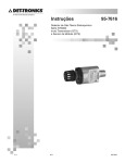
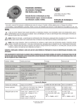
GEP-6612
Rev. F 100900
Ref. I.D.: 16128
3160 WEST HEARTLAND DRIVE LIBERTY, MISSOURI 64068-3385
PHONE: (816) 792-1500 FAX: (816) 792-2277 / 5447
BDI-FLXTM 2W-IS BURST DISC SENSOR SYSTEM
OPERATOR’S MANUAL
IMPORTANT
USER SHOULD READ CAREFULLY AND UNDERSTAND
THIS MANUAL BEFORE INSTALLING, OPERATING OR
TESTING THIS UNIT
TABLE OF CONTENTS
I.
PRODUCT DESCRIPTION ………………………..……………………………………………………………………………………
3
II. SPECIFICATIONS ……………………..……………..……………………………………………………………………………………
4
III. HANDLING AND UNPACKING ……………………………………………………….…………………………………………....
4
IV. STORAGE ……………………………………………………………………………………………………………………………………
5
V. INSTALLATION ……………………………………………………………………………………………………………………………
5
VI. MAINTENANCE …………………………………………………………………………………………………………………….……..
9
VII. LIMITED WARRANTY ……………………………………………………………………………………………………………………
9
VIII. DISCLAIMER OF WARRANTIES …………………………………………………………………………………………………….. 9
IX. DISCLAIMER OF CONSEQUENTIAL DAMAGES ………………………………………………………………………………. 10
X. WARRANTY EXCLUSIONS ……………………………………………………………………………………………………………… 10
©2011, 2012, 2014 Continental Disc Corporation
2
I.
PRODUCT DESCRIPTION
WARNING: For full liquid applications: The BDI-FLX Sensor requires dynamic movement to signal.
Slow reversal of the rupture disc, such as with liquid thermal expansion, will not cause the BDI-FLX
Sensor to indicate. A small crack in a rupture disc score will not cause the BDI-FLX Sensor to indicate.
Note that the BDI-FLX Sensor is designed to indicate within a few milliseconds, so full reversal and full
opening of the rupture disc must occur within a few milliseconds. If full liquid flow at set pressure or a
gas head will not be present during rupture of disc, contact CDC for evaluation.
TM
The BDI-FLX Burst Disc Sensor Systems are designed to continuously monitor the status of rupture
discs and output a switch signal to a system when such rupture discs have relieved an over-pressure
condition. The system is comprised of two components: the BDI-FLX sensor and the BDI-FLX interface
cable. The interface cable processes the sensor’s signal and outputs a switch type signal.
The BDI-FLX Burst Disc Sensor Systems contain numerous advances in rupture disc burst monitoring
and alarm switching technology. Designed to meet the needs of a variety of applications and diverse
industries, the BDI-FLX product family includes three models:
•
•
•
BDI-FLX 2W-IS for use in hazardous environments and intrinsically-safe applications
BDI-FLX 2W-NIS for direct PLC or discrete input
BDI-FLX 4W-NIS for use as dry contact switch that can be used a wide variety of power options
and control/alarm inputs
This user manual provides detail specifications, electrical system requirements, wiring and operating
instructions for model 2W-IS.
The BDI-FLX 2W-IS model is a 2-wire intrinsically safe device for use with a safety barrier (barrier not
provided). It provides a digital switching signal over a single pair of wires. It is designed in compliance
with ATEX and IECEx requirements for use in intrinsically safe applications as category 1 equipment for
Group II and Group III, i.e., gas and dust areas when it is connected to a compatible intrinsically safe
i
isolated repeater or barrier .
The interface cable contains a built-in microprocessor that processes the sensor signal and produces a
logic output, offering plant operators a reliable rupture disc status signal. The unit outputs a continuous
current signal (4.5 mA typical) as disc in normal operation and requires maximum 0.85 mA leakage
current flowing through the load which is in-series connected to the module when switching OFF.
The interface cable incorporates a “failsafe” design: should there be a disc burst or an interruption of the
sensor signal or power line, the output of the interface module is always switched automatically to the
safe “OFF” condition.
3
II.
SPECIFICATIONS
Electrical Specifications
Power Supply:
6 ~12 VDC
Operating Temperature:
BDI-FLX Interface Cable -40°C to 70°C (-40°F to 158°F)
BDI-FLX Sensor -40°C to 204°C (-40°F to 400°F)
Field sensor operating current:
15 µA
Output configuration:
ON: 4.5 mA typical (min: 2.5 mA; max: 4.85 mA)
OFF: max: 850 µA; min: 75 µA
Power-up Time Delay:
62 ms
Polarity Protection:
Protected (up to 60 V)
Transient Over-voltage Protection: Protected
Output Cable:
Approvals:
Marking Code:
18 AWG, shielded twisted pair (STP) PVC tray cable (TC), CMG
under UL-NEC
CE, ATEX, IECEx, UL/cUL
ATEX (Directive 94/9/EC):
0359
II 1 G D
Ex ia IIC T4 Ga, Ex ia IIIC T135°C Da
IECEx (IEC Ex Scheme):
Ex ia IIC T4 Ga, Ex ia IIIC T135°C Da
UL (cULus Hazloc):
Refer to UL C/US Intrinsic Safety Control Drawing GEP-6615
Mechanical Specifications
Housing Material:
Housing Inflammability Class:
Housing Dimensions:
Mounting:
Cable Gland Material:
Output Cable OD:
Degree of Protection:
ABS
UL 94 V-0
3.1 x 2.1 x 1.1 in. / 79 x 54 x28 mm
Wall panel
Nylon
5.8 mm
IP67
III. HANDLING AND UNPACKING
The personnel responsible for the assembly, operation, inspection and maintenance of the BDI-FLX
Burst Disc Sensor System must be appropriately qualified.
The BDI-FLX Burst Disc Sensor System is a precision device. Always follow these guidelines when
handling and unpacking the product to prevent damage:
A. Use care when unpacking/handling the product.
B. Inspect the package for damage or missing items upon delivery.
C. Mark any damage or missing items and report it to Customer Service at Continental Disc
Corporation.
4
WARNING:
POTENTIAL ELECTROSTATIC CHARGING HAZARD!
When installed in hazardous locations, precautions must be taken to ensure
electrostatic charging cannot occur. Prevent unintentional contact or clean with a
dry cloth. Clean ONLY with a damp cloth. Do NOT use any solvent.
CAUTION:
Always observe the applicable local standards, regulations and safety
requirements. Failure to comply with required safety precautions may result in
serious injury or damage to people/property/product and loss of all claims for
damages.
IV. STORAGE
The BDI-FLX interface cable is to remain packed in the box in which it is shipped until ready for
installation. This unit should be stored in a cool dry atmosphere with ambient temperatures within 40ºC to 50ºC
(-40ºF to 122ºF).
V.
INSTALLATION
WARNING:
These installation and servicing instructions are for use by qualified personnel only.
To avoid injury and electrical shock, do not perform any servicing other than that
contained in this manual. The installation and wiring of this unit should be performed
in accordance with the latest edition of the governing Electrical Code.
WARNING:
Disconnect power to the unit before wiring.
NOTE:
This section describes the procedures and requirements for connecting the BDI-FLX 2WIS interface cable to the user’s system. For installation of the BDI-FLX sensor please
refer to “Preparation and Installation of the BDI-FLX Sensor and connection to the BDIFLX Interface Cable Assembly” document provided with the BDI-FLX sensor.
1. The BDI-FLX Burst Disc Sensor System is not equivalent to a traditional mechanical switch. The
user must read carefully the installation procedure for the selected model and verify that their
system meets the required conditions for the specific unit.
2. The BDI-FLX 2W-IS System drops a certain amount of voltage in operation, typically about 5.5 V.
This voltage drop determines how many volts the load (e.g., the safety barriers or control system
digital input channel) can obtain from the supply voltage. If the supply voltage minus the voltage
drop is not sufficient for load normal operation, the device will not turn ON. Check the receiving
system manufacturer’s specifications for the input ON voltage threshold.
3. The BDI-FLX 2W-IS System leaks a small amount of current through the loop when they output a
switching “OFF” signal. This current value is typically 0.075 mA at normal environmental condition
and will not be over 0.85 mA under specified operating conditions. The current flows through the
load and produces a small voltage across the load. If this voltage is greater than the value that will
allow it to turn ‘OFF”, the load will remain in the ON state although the sensor unit has switched
OFF. Check the manufacturer specifications for the control input OFF voltage threshold.
4. The BDI-FLX 2W-IS System output is designed as Normally Closed (ON state). Each time the unit
is powered up, the output stays OFF for about 62 ms (power-up time delay) then switches ON. This
warm-up period allows the power line to stabilize. User should examine their receiving system
power-up set time for logic adaptation.
5. The BDI-FLX Burst Disc Sensor System is designed for continuous monitoring of disc burst. When
powering up on initial installation or upon restoring power from a lost power condition, the unit will
reset itself automatically. When the BDI-FLX system trips an OFF signal as a result of a disc burst,
the user should replace the rupture disc and BDI-FLX sensor. The user can reuse the interface
cable. Re-powering the system without replacing the BDI-FLX sensor could result in a false normal
(ON) signal.
5
WARNING: Installation of intrinsically safe equipment must be performed in accordance with the
requirements of the government and other local authority having jurisdiction. System
components and installation methods must be approved by the appropriate recognized
approval authority.
Prior to installation, review the certification marking on the device label to confirm it is
appropriately certified for your region, suits your site classification and complies with your
hazardous area safety philosophy.
When the BDI-FLX 2W-IS Burst Disc Sensor System is used in an explosive area, it must be
operated in conjunction with a safety barrier or isolator suitable for the hazardous area
classification and substance group. The BDI-FLX 2W-IS System entity parameters must
match in accordance with the safety barrier or isolator entity parameters. This is to insure
safe operation within explosive environments.
CAUTION: Lead polarity must be observed when connecting the two wires to the barrier input
channel.
Required System Conditions:
Safety Entity Parameter Requirements:
1. 2W-IS maximum intrinsically safe input parameters:
Ui = 12 V; Ii = 60 mA; Pi = 180 mW
2. 2W-IS equivalent internal parameters:
Ci = 1.11 µF; Li = 0
Associate IS Barrier entity parameters must meet the following requirements:
Uo ≤ 12 V
Io ≤ 60 mA
Po ≤ 180 mW
Co ≥ 1.11 + Ccable (µF)
Lo ≥ Lcable
SPECIAL CONDITIONS FOR SAFE USE
When located in a Zone 0 hazardous area, the user shall ensure that electrostatic charging of the
interface enclosure cannot occur.
When located in Zone 1 or Zone 2, the interface enclosure represents an electrostatic hazard and the
enclosure shall only be cleaned using a damp cloth. Solvents shall not be used.
Operating Requirements:
1. Max. voltage drop across the barrier (Vdrop) with ON state current of 4.5 mA:
Vdrop ≤ Vpw – 5.5V
(Vpw is the in-series power supply voltage)
2. OFF state input signal current for the barrier (IOFF)
IOFF ≥ 0.85 mA
3. ON state input signal current for the barrier (ION)
ION ≤ 2.5 mA
NOTE: The BDI-FLX 2W-IS Burst Disc Sensor System intrinsically safe entity parameters should not be
mixed with equipment functionality (operating) parameters. Those safety barriers that satisfy the
entity parameter requirements do not guarantee proper functioning of the BDI-FLX System.
Both requirements must be met for safe and proper operation.
6
Safety Barrier Selection Considerations:
The BDI-FLX 2W-IS Burst Disc Sensor System output is typically connected to the load through an
intrinsically safe barrier or isolated repeater. Proper selection of the barriers or isolators is essential.
The barrier input power and capacitance/inductance capacity must be within the BDI-FLX System
permitted range.
The isolated repeater or barrier must keep a proper activation current and provide the BDI-FLX 2W-IS
System with enough voltage for a reliable operation.
The BDI-FLX 2W-IS System output is compatible with NAMUR (IEC 60947-5-6) sensor current level.
Most NAMUR sensor applicable intrinsically safe switching amplifiers are suitable and can be found in
various safety barrier manufacturers catalogs.
NOTE: Certain shunt diode (Zener) barriers are designed for mechanical switch (dry contact) input
applications. These are not recommended for use with the BDI-FLX 2W-IS System since these
barriers typically provide highly restrictive voltage for the hazardous field devices. However,
some Zener barriers can be utilized if both the parameter entity and the 2W-IS operating
conditions are met. If utilizing Zener barriers, the user must verify the complete loop resistance
including barrier end-to-end resistance and constant voltage drop.
For new installations the selection of an isolator is recommended. Isolated barriers can typically drive
higher load resistance than a Zener barrier. Other advantages of isolators include isolation between
input, output and power. Most isolators provide short circuit protection and regulated power to the field
and no I.S. earth required, thus avoiding complex ground loop problems.
The following are recommended barriers that can be used with the BDI-FLX 2W-IS system:
IS Isolators:
MTL:
Pepperl+Fuchs:
R. STAHL:
Weidmuller:
Phoenix:
MTL551x Series; MTL5018
KCD2-SR-Ex1.LB
9170/.0-1x Series
ACT20X-HDI-SDO Series
PI-EX-NAM Series
Zener barriers:
MTL:
MTL774x Series
Wiring Diagram:
2W-IS connected through an isolated barrier
7
2W-IS connected through a zener diode barrier
Note: The shield (drain wire) of the BDI-FLX System output cable should be grounded at the barrier site
and the shield throughout the cable must be connected to ground at a single point.
The shield of shielded cable from barrier to control room should be grounded at the control panel
site and NOT connected to the barrier site.
The Zener diode barrier safety ground requires the ground path must have less than 1 Ω of
resistance from the barrier to the main earth ground electrode.
Installation:
1. Mount the BDI-FLX Interface Cable Enclosure
Bolt the BDI-FLX interface cable enclosure to a wall or rack using mounting bracket hardware.
Consider the distance and location for convenient sensor connection.
The enclosure can be installed in hazardous or non-hazardous environment. The interface cable
must always be connected through a safety barrier located at the non-hazardous area for all
intrinsically safe applications.
2. Connect BDI-FLX Sensor to the BDI-FLX Interface Cable model 2W-IS
Connect the BDI-FLX sensor pigtail to the BDI-FLX interface cable through the M12 connector. After
insertion, fasten the M12 screw ring to lock the connection.
3. Connect Output Cable
Terminate the output cable wires according to the wiring diagram. The 2W-IS two wires must be
routed into the appropriate barrier terminals (typically the discrete input channel).
Terminate all other correlated wires and ground properly before operation.
CAUTION:
To properly maintain the intrinsic safety of the system and to ensure immunity
of the system to external interference, appropriate shielded cable should be
used. Individual runs should use a shielded twisted pair (STP) cable such as
Belden #1032A or equivalent. Multiple runs from safety barrier to field junction
box should use individual or overall shielded multiple twisted pairs cable such
as Belden #9504, #9328 or equivalent. Remove a maximum 20 mm of insulation
from wires prior to connecting.
4. Final Check
Check all wiring to ensure proper connections with no unwanted possible shorts, grounds, or open
circuits.
8
5. Energize Power to Unit
With the disc, sensor system, safety barrier and output load installed and properly connected the
unit can be powered and ready for operation.
VI. MAINTENANCE
The BDI-FLX interface cables have been designed to operate with little maintenance required. Periodic
checks should be made to ensure the units are clean and free from contaminating, humid or hot
atmospheres, and are in good physical and electrical condition.
Should the system fail to function properly, the user should check for the following items where
applicable:
A. You have the correct BDI-FLX sensor model for your application.
B. All specified conditions of the connected system listed in Section V are met
C. The unit is connected to the barrier or control input channel in the correct polarity
D. There is no ground loop through the cable signal transmission
E. The BDI-FLX sensor pigtail cable has been properly connected to the interface cable prior to
powering the unit
F. The power is on
G. All wiring is connected properly per this instruction manual
H. The connected barriers or input channels are working properly
I.
The user receiving system (PLC/DCS, etc.) is functioning properly
J.
There is no short or open circuit in the disc sensor, interface cable or connectors
K. The disc and sensor are in good condition
Note:
If the sensor has tripped an OFF signal due to disc burst or signal interruption, the system
needs to be reset following instructions listed in Section V.
The BDI-FLX interface modules are designed with industrial category components and every effort has
been made to make the unit as easily serviceable as possible. Should there be a problem before or
during operation please contact Continental Disc Corporation Customer Service for assistance. Do not
repair or modify the product without consultation of Continental Disc Corporation. Disassembly of the
unit and/or replacement of components may lead to improper function of the system and safety hazards.
VII. LIMITED WARRANTY
Products manufactured by Continental Disc Corporation have a warranty against defective workmanship
and material for a period of one year after date of invoice. In no event shall Continental Disc
Corporation’s liability for damages with respect to any of the products furnished under this Agreement
exceed the charges previously paid by the customer to Continental Disc Corporation for such products.
Buyer’s sole remedy for breach of this Agreement is repair or replacement of defective parts furnished
by Continental Disc Corporation, which have been returned to Continental Disc Corporation’s factory at
purchaser’s expense. It is expressly agreed between purchaser and Continental Disc Corporation that
the remedy of repair and replacement is the exclusive and sole remedy of the purchaser.
VIII. DISCLAIMER OF WARRANTIES
Except as specifically provided in this Agreement, there are no warranties, expressed or implied,
including, but not limited to any implied warranties of merchantability or fitness for a particular purpose.
9
IX. DISCLAIMER OF CONSEQUENTIAL DAMAGES
In no event shall Continental Disc Corporation be liable for consequential damages, including but not
limited to damages for loss of use, damages for lost profits, and damages for resulting harm to property
other than the Continental Disc Corporation assemblies and their component parts.
Customer acknowledges and understands that the provisions of these additional terms and conditions,
including this paragraph concerning disclaimer of consequential damages and limitation or remedy,
apply fully to the purchase of the products.
X.
WARRANTY EXCLUSIONS
This warranty does not apply in the event of misuse or abuse of the product or as a result of
unauthorized alterations or repairs. It is void if the serial number is altered, defaced, or removed.
10