1
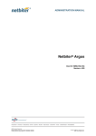
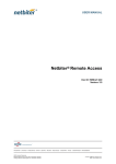
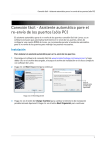
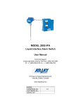
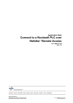
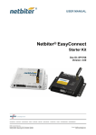
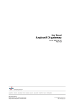
User Manual For Netbiter Tank Sensor HMS Industrial Networks AB Post address: Box 4126 300 04 Halmstad SWEDEN Visitor’s address: Stationsgatan 37 302 45 Halmstad SWEDEN Telephone: + 46 35 17 29 00 Fax: + 46 35 17 29 09 E-mail: [email protected] Web: www.netbiter.com User Manual Netbiter Tank Sensor Doc: HMS-27-215, Rev. 1.0 Important User Information This document is intended to provide a good understanding of the functionality offered by the Netbiter Tank Sensor. Liability Every care has been taken in the preparation of this manual. Please inform HMS Industrial Networks AB of any inaccuracies or omissions. The data and illustrations found in this document are not binding. We, HMS Industrial Networks AB, reserve the right to modify our products in line with our policy of continuous product development. The information in this document is subject to change without notice and should not be considered as a commitment by HMS Industrial Networks AB. HMS Industrial Networks AB assumes no responsibility for any errors that may appear in this document. There are many applications of this product. Those responsible for the use of this software must ensure that all the necessary steps have been taken to verify that the applications meet all performance and safety requirements, including any applicable laws, regulations, codes or standards. HMS Industrial Networks AB will, under no circumstances, assume liability or responsibility for any problems that may arise as a result from the use of undocumented features, timing, or functional side effects found outside the documented scope of this product. The effects caused by any direct or indirect use of such aspects of the product are undefined, and may include e.g. compatibility issues and stability issues. The examples and illustrations in this document are included solely for illustrative purposes. Because of the many variables and requirements associated with any particular implementation, HMS Industrial Networks AB cannot assume responsibility for actual use based on these examples and illustrations. Intellectual Property Rights HMS Industrial Networks AB has intellectual property rights relating to technology embodied in the product described in this document. These intellectual property rights may include patents and pending patent applications in the US and other countries. Trademark Acknowledgements Netbiter® is a registered trademark of HMS Industrial Networks AB. All other trademarks are the property of their respective holders. Copyright© HMS Industrial Networks AB November 2013 HMS Industrial Networks AB Page 2 (27) User Manual Netbiter Tank Sensor Doc: HMS-27-215, Rev. 1.0 History Revision Date Description Author 1.0 2013-11-18 First official release SDa Terminology Netbiter Argos Data Center Netbiter Argos data center is a solution that collects and stores data from connected field systems. Netbiter Argos contains various features such as alarm management, reporting and much more. Gateway A gateway is a Netbiter EasyConnect gateway, all of which are compatible with Netbiter Argos. Field System (or site) A field system is a Netbiter Gateway and its connected devices, taken together as a unit. A field system can contain multiple devices, but only one gateway. (Modbus) Device A Device is the equipment to be monitored and which is connected to a gateway, using e.g. Modbus. Examples of devices include energy meters, ultrasonic tank sensors and free cooling controllers. HMS Industrial Networks AB Page 3 (27) User Manual Netbiter Tank Sensor Doc: HMS-27-215, Rev. 1.0 Table of Contents 1 Planning the Installation ............................................................................................. 6 1.1 Required Tools & Materials (not supplied) .........................................................................7 1.2 Package Contents ................................................................................................................8 1.3 Optional Items .....................................................................................................................8 2 Hardware Installation ................................................................................................. 9 2.1 Preparations on site .............................................................................................................9 2.2 Determine the Mounting Position .......................................................................................9 2.3 Mounting on a Completely Flat Surface ............................................................................11 2.4 Mounting on an Uneven or Rounded Surface ...................................................................11 2.5 Connect Cables ..................................................................................................................12 2.5.1 Connect Cable to Sensor ..............................................................................................12 2.5.2 Install Optional 5m Modbus Extension Cables ............................................................12 2.5.3 Connect Cable to Netbiter Gateway ............................................................................12 2.6 Installation Checklist ..........................................................................................................13 3 Tank Dimensions ...................................................................................................... 14 4 Import the Netbiter Tank Sensor Profile.................................................................... 15 5 Add and Configure Netbiter Tank Sensor at Netbiter Argos ....................................... 16 5.1 Add the Tank Sensor as a Device .......................................................................................16 5.2 Default Modbus Settings ...................................................................................................16 5.3 Configure Tank Parameters ...............................................................................................17 5.4 Configure Level Alarms ......................................................................................................18 5.5 Configure Theft Detection .................................................................................................19 6 Dashboard for Tank Sensor (included in profile) ........................................................ 20 6.1 Creating Custom Dashboards ............................................................................................21 7 Reports .................................................................................................................... 22 7.1 Configure and run the Tank Volume Report .....................................................................23 8 Supported Parameters for the Netbiter Tank Sensor ................................................. 24 8.1 Parameter Group Alarms ...................................................................................................24 8.2 Parameter Group Internal Temp and Humidity ................................................................24 8.3 Parameter Group Measurements......................................................................................24 8.4 Parameter Group Modbus Configuration..........................................................................24 8.5 Parameter Group Tank Setup ............................................................................................25 HMS Industrial Networks AB Page 4 (27) User Manual Netbiter Tank Sensor Doc: HMS-27-215, Rev. 1.0 8.6 Parameter Group Theft Detection/level alarms setup......................................................25 9 Appendix A – Specifications ...................................................................................... 26 9.1 Wiring.................................................................................................................................26 9.2 Dimensions ........................................................................................................................26 10 Appendix B – Limitations .......................................................................................... 27 HMS Industrial Networks AB Page 5 (27) User Manual Netbiter Tank Sensor Doc: HMS-27-215, Rev. 1.0 1 Planning the Installation The main function of the Netbiter Tank Sensor is to measure the level in a given tank. This basic functionality is extended by a number of features, thus providing access to the following: • • • • Exact tank levels at any time Historical reports of consumption over time Estimations of when to refill Alarms for overfilling, high/low levels and abnormal usage (possible theft) The central element of this solution is the Modbus-enabled Ultrasonic Tank Sensor. Manufacturer Pepperl & Fuchs Product ID SP1616 Description Image Smart ultrasonic sensor with built-in temperature compensation Supported features • • • • Theft detection Volume calculation Alarm for low level Alarm for high level Please note that the supplied sensor is not certified for ATEX or HAZLOC environments. HMS Industrial Networks AB Page 6 (27) User Manual Netbiter Tank Sensor Doc: HMS-27-215, Rev. 1.0 1.1 Required Tools & Materials (not supplied) The following tools and materials are required for the installation of the tank sensor: • • • Electric drill Drill-mountable hole cutter for metal, 30mm (1 1/8” – 1 ¼”) diameter Center punch Tape measure (to measure tank) • • Stripping tool for electrical wiring (0.52.5mm2) Wire cutter Half-round/flat file 2 x M5x35mm screws (or equivalent) Thread tap for above screws HMS Industrial Networks AB Page 7 (27) User Manual Netbiter Tank Sensor Doc: HMS-27-215, Rev. 1.0 1.2 Package Contents When the package arrives on site, please verify that it contains the items in the list below. Qty Item 1 Tank Sensor 1 Gasket (rubber) 1 Image Washer (metal) 1 10m, 5-wire cable with connection plug and open end 1 Installation Guide 1.3 Optional Items Also available are 5m extension cables, for covering greater distances between the sensor and the Netbiter Gateway. See page 12 for further details. HMS Industrial Networks AB Page 8 (27) User Manual Netbiter Tank Sensor Doc: HMS-27-215, Rev. 1.0 2 Hardware Installation 2.1 Preparations on site 1. Verify that tools & materials required are available according to the list on page 7. 2. Open the packages and check that they contain the material as described on page 8. 3. Verify that there is sufficient installation space on top of the tank for the sensor. The sensor’s total dimensions are (W x H x D): 125 x 30 x 76.5 mm. 2.2 Determine the Mounting Position The tank sensor should be mounted on the top surface of the tank. The sensor requires a round opening with diameter 30mm (1⅛” – 1¼”), for the ultrasonic sound to enter the tank. To prevent dirt and rain entering the tank, a gasket is provided to seal the mounting area. It is recommended to leave an area of 70─100mm free space around the sensor. Important notes: • Do not install the sensor so that it is exposed to direct sunlight, as this may affect its accuracy. If necessary, mount a shield to protect against direct sunlight. • Avoid installing in positions that may lead to impaired function due to dust or dirt. • Avoid installing the sensor adjacent to power cables. • There must be no obstacles between the sensor and the bottom of the tank, as this might affect the passage of the ultrasonic sound. If there are stabilizing beams inside the tank, ensure the sensor is not mounted over these. HMS Industrial Networks AB Page 9 (27) User Manual Netbiter Tank Sensor Doc: HMS-27-215, Rev. 1.0 • If the sensor is to be mounted close to a tank wall, ensure there are no objects directly below the sensor. Ensure that the sensor has a free line of sight to the bottom of the tank, as shown here. • If the upper surface of the tank is not flat (e.g. on the top of a horizontal cylindrical tank), ensure that the sensor placement is as horizontal as possible. IMPORTANT! Mounting on a surface that is not completely flat will require the use of the supplied rubber gasket and metal washer. This is to ensure achievement of the IP65 protection rating. HMS Industrial Networks AB Page 10 (27) User Manual Netbiter Tank Sensor Doc: HMS-27-215, Rev. 1.0 2.3 Mounting on a Completely Flat Surface Once the mounting position has been determined, the following steps should be followed: 1. Using the center punch, mark the position for the center of the 30mm (1⅛” – 1¼”) hole through which the sensor will transmit its ultrasound signals. 2. Using the electric drill and hole cutter, cut out the 30mm hole. Avoid drill debris falling into the tank. 3. Remove any drill burr with the file. 4. Clean the tank surface. Do not allow drilling debris to fall into the tank. 5. Place the sensor over the hole and mark out the positions for the 2 screw holes. 6. Drill the holes and thread them. 7. Carefully fix the sensor to the tank. 2.4 Mounting on an Uneven or Rounded Surface 1. Using the center punch, mark the position for the center of the 30mm (1⅛” – 1¼”) hole through which the sensor will transmit its ultrasound signals. 2. Using the electric drill and hole cutter, cut out the hole. Try to avoid drill debris falling into the tank. 3. Remove any drill burr with the file. 4. Clean the tank surface. Do not allow drilling debris to fall into the tank. 5. Place the sensor over the hole and mark out the positions for the 2 screw holes. 6. Drill the holes and thread them. 7. Place the gasket and metal washer over the drilled holes, as shown here. Carefully fasten the sensor in place using the 2 screws. HMS Industrial Networks AB Page 11 (27) User Manual Netbiter Tank Sensor Doc: HMS-27-215, Rev. 1.0 2.5 Connect Cables Connect Cable to Sensor 2.5.1 A pre-commissioned 5-wire, 10m cable is included in the package. Connect the end with the plug to the sensor. The other end of the cable should be connected to the Netbiter, see below for details. Install Optional 5m Modbus Extension Cables 2.5.2 To cover greater distances between the tank sensor and the Netbiter Gateway, optional 5m Modbus extension cables with male and female plugs are also available. The maximum supported Modbus cabling length is 100m. Connections using extension cables should be wired in this sequence: Sensor 2.5.3 Extension cable Standard cable Netbiter Connect Cable to Netbiter Gateway 1. At the other end of the cable, remove 8-9mm of insulation from the wires. Note that the grey wire is not used. 2. Connect the individual wires to the Netbiter Gateway, consulting the table below for the correct connections. Wire color Black White Blue Brown Grey Signal/function RS485 Line A RS485 Line B 0V +24 V EC150 Pin EC220 Pin EC250 Pin EC350 Pin RS485 A RS-485 A RS485 TD(A) RS485 A RS485 B RS-485 B RS485 TD(B) RS485 B If using the same power source for both the tank sensor and the Netbiter, check that there is sufficient power available. The sensor requires 24V DC and 0.6W Not used HMS Industrial Networks AB Page 12 (27) User Manual Netbiter Tank Sensor Doc: HMS-27-215, Rev. 1.0 2.6 Installation Checklist When the installation is complete, verify the items in the checklist below. Check: OK Sensor mounted on tank surface tightly enough to prevent water and dirt from entering the tank. Sensor mounted as horizontally as possible on top of the tank, with no visible tilting. Black wire connected to Line A of the RS-485 connector. White cable connected to Line B of the RS-485 connector. Brown cable connected to (+) Blue cable connected to (-) Audio check: when power is connected to the sensor it should issue frequent clicking sounds. HMS Industrial Networks AB Page 13 (27) User Manual Netbiter Tank Sensor Doc: HMS-27-215, Rev. 1.0 3 Tank Dimensions An important part of the configuration process of the Netbiter Tank Sensor involves registering the type and dimensions of the tank. This step is described in detail in section 5.3 on page 17. Four tank types are supported, as depicted below. Use the illustrations to find the measurements required for each type. These dimensions and the tank level measurements will be used to calculate the remaining tank contents. The tank capacity according to the manufacturer should be possible to find somewhere on the tank itself. Vertical cylindrical tank Rectangular tank Height Height Radius Width Horizontal cylindrical tank with flat ends Radius Horizontal cylindrical tank with arched ends Minor Radius Radius Length HMS Industrial Networks AB Page 14 (27) User Manual Netbiter Tank Sensor Doc: HMS-27-215, Rev. 1.0 4 Import the Netbiter Tank Sensor Profile Communication between devices connected to a Netbiter EasyConnect Gateway requires a device template, or a device profile, both of which provide the mapping between the device and the Netbiter EasyConnect Gateway. • • A device template is a description of the parameters for a connected device. It contains information about the available parameters and their data types, and can include predefined scaling and offsets. A device profile too contains a device template, but it also provides further configuration designed to provide a complete interface for the user, including e.g. dashboards, visualizations, logs, alarms and various gateway settings. IMPORTANT! The device template or profile must be available in the user account at Netbiter Argos before adding a device. Follow these steps to import the Netbiter Tank Sensor device profile into the user account: 1) Visit support.netbiter.com and locate the available device profiles. 2) Select the Netbiter Tank Sensor Profile. 3) Follow the onscreen instructions to add the profile. HMS Industrial Networks AB Page 15 (27) User Manual Netbiter Tank Sensor Doc: HMS-27-215, Rev. 1.0 5 Add and Configure Netbiter Tank Sensor at Netbiter Argos Now that the device profile has been added to the user account, the Netbiter Tank Sensor can be added as a device and configured at Netbiter Argos. 5.1 Add the Tank Sensor as a Device 1. Select the field system (Netbiter Gateway) that the Netbiter Tank Sensor is connected to. This is done from the menu Management >> All systems. Select the field system by clicking on the system name. 2. Now go to the Configuration menu for the field system, and add the tank sensor as a new device, using the device profile Netbiter Tank Sensor as added to the account in section 4. 3. After following all the steps to add the device, synchronize the configuration. Please see the Netbiter Argos Administration Manual for further information on adding devices. 5.2 Default Modbus Settings Please see section 8.4 for the default Modbus settings. HMS Industrial Networks AB Page 16 (27) User Manual Netbiter Tank Sensor Doc: HMS-27-215, Rev. 1.0 5.3 Configure Tank Parameters After the Netbiter Tank Sensor has been added to a field system at Netbiter Argos, all the configurable parameters will be available for configuration. The focus here is on the parameters required to initially get the sensor up and running. 1. From the start page at Netbiter Argos, in the list at Presentation >> All Systems, click the link to Browse Devices and find the system containing the tank sensor. Then select Netbiter Tank Sensor v1.0. 2. Select the group Tank Setup. The parameters here will determine the volume of the tank. 3. Click the Refresh button to the right. 4. Select a Tank type from the drop-down list of available types and click Set. The dimension fields required for the selected tank will be populated with default values, thus indicating which fields are required. Fields that are not valid for the selected tank type will show -1. HMS Industrial Networks AB Page 17 (27) User Manual Netbiter Tank Sensor Doc: HMS-27-215, Rev. 1.0 5. Enter the correct dimensions for the tank the sensor is connected to and click the Set button. Also click the Refresh button again. The Calculated tank capacity will now be displayed. 6. The 100% tank level must be configured if intending to use the overfill alarm, which triggers when the tank level rises above this value. This value is the maximum allowed volume in liters for the tank, and must be set to a value lower than the calculated tank capacity. 100% tank level. Overfill alarm triggers here. If set to 0, the overfill alarm is disabled and only the calculated tank capacity will be used for alarms. 5.4 Configure Level Alarms High level alarm triggers here (default 90%) Low level alarm triggers here (default 20%) Example alarm configuration with 100% tank level and overfill alarm This group of parameters allows the settings of the limits that will trigger alarms when these limits are exceeded. 1. Click the Refresh button to the right, to allow editing of the settings. 2. First configure the limits for the High and Low level alarms (parameters a & b), which are expressed as percentages of the calculated tank capacity. The low level alarm warns of an emptying tank, and the high level alarm provides notification when the maximum is being approached. After entering a value, click the Set button to save it. Note that when 100% tank level is configured (see above), these alarm levels will automatically use this parameter value for the tank level, instead of the calculated tank capacity. 3. If frequent minor fluctuations in the levels are anticipated, then a Hysteresis percentage value (parameter c) can also be set, to prevent unnecessary triggering of alarms. For more on hysteresis, see the Netbiter Argos Administration Manual. HMS Industrial Networks AB High level alarm triggers here (default 90%) Low level alarm triggers here (default 20%) Example alarm configuration without overfill alarm Page 18 (27) User Manual Netbiter Tank Sensor Doc: HMS-27-215, Rev. 1.0 5.5 Configure Theft Detection 1. Set Theft detection (parameter d) to ON and click the Set button. 2. The next step is to define the loss rate, which is calculated by the parameters: • • Theft liters – liters (parameter e) Theft time constant – seconds (parameter f) These 2 parameters together (liters per seconds) define the maximum allowed loss rate of tank contents. Enter the required values and click the Set button for each one. 3. Parameter g defines the value at which to Trigger theft alarm. The parameter value is an integer, and the unit is a 10-second interval, so 1=10s, 2=20s, etc. The default value 3 (30s) implies that the maximum loss rate (liters/s) must be exceeded at 3 consecutive measurement intervals, i.e. at 10s, 20s and 30s before the theft alarm is triggered. This parameter makes it possible to detect even a very fast drop in tank volume. 4. The final parameter (h) defines the time period after which to Reset theft alarm. This defines a minimum period of inactivity (i.e. no further losses) before the alarm is considered to be inactive. This parameter is also defined in periods of 10 seconds (as above) and the default value is 10 (i.e. 100s). Note that the default values (3 & 10) for parameters g and h are suitable for most conditions and do not normally need to be changed. Example Configuration The theft detection settings are configured as follows: • • • • Theft liters = 6 (l) Theft time constant = 60 (s) Trigger theft alarm = 3 (30s) Reset theft alarm = 12 (120s) Using these settings will trigger a theft alarm if the loss rate is greater than 6 liters/min at 3 consecutive measurements. The alarm will have the status triggered as long as the consumption rate remains at this elevated level. After the loss rate drops back below the threshold level of 6 l/s, the alarm will remain triggered for a further 100 seconds. During this period, if even a single measurement returns a consumption rate above the threshold value, then Reset theft alarm will be reset and a new period of 100 seconds must pass before the alarm returns to status Normal. Consider also the limitations in the accuracy and resolution of the sensor. See page 27 for further details. HMS Industrial Networks AB Page 19 (27) User Manual Netbiter Tank Sensor Doc: HMS-27-215, Rev. 1.0 6 Dashboard for Tank Sensor (included in profile) A dashboard is a customized graphic presentation page for a field system. A pre-configured dashboard for managing tank levels will be available in the Netbiter Argos account after adding the tank sensor using the Netbiter Tank Sensor device profile, see section 4. A dashboard is displayed as a tab on the presentation page for the field system, as in the example below. Dashboards are made up of widgets. Netbiter Argos provides various widgets for displaying lists and graphical representations of parameters from a field system. These widgets are: • • • • • A) Live values displayed as a list B) Live values (including alarm status) shown in a graphical drawing of the field system C) The latest logged values as a list D) Logged values in a graph E) Alarms shown as a list A B B C D E HMS Industrial Networks AB Page 20 (27) User Manual Netbiter Tank Sensor Doc: HMS-27-215, Rev. 1.0 6.1 Creating Custom Dashboards Apart from using the dashboard supplied with the tank sensor device profile, it is also possible to create custom dashboards of your own. This can be done by manually incorporating any of the available parameter values into a custom dashboard, as logs, visualizations or alarms. For more on creating and using dashboards, please see the Netbiter Argos Administration Manual. HMS Industrial Networks AB Page 21 (27) User Manual Netbiter Tank Sensor Doc: HMS-27-215, Rev. 1.0 7 Reports Reports are created by the Netbiter Argos account administrator. Users have access to finished reports from the project(s) they have access to. Reports can be configured to run at regular intervals, and are available to be downloaded and saved. The illustration below shows the report tab with the report download option as available to a standard user. Reports generated by Netbiter Argos provide clear and precise presentations of user data in various formats, such as lists, graphs and diagrams, as in the example below. The data used as the source for reports is taken from the various parameters provided by a device connected to a Netbiter Gateway, in this case the Netbiter Tank Sensor. Reports may consist of several pages and are mostly available in PDF format. HMS Industrial Networks AB Page 22 (27) User Manual Netbiter Tank Sensor Doc: HMS-27-215, Rev. 1.0 7.1 Configure and run the Tank Volume Report The tank volume report contains information about a tank on a specific site, and provides statistical information on the tank contents. 1) Select Add report. 2) Enter the report name, the frequency to run at, assign users with access, and add the required report parameters. 3) Click the Add button. For more on using reports, see the Netbiter Argos Administration Manual. HMS Industrial Networks AB Page 23 (27) User Manual Netbiter Tank Sensor Doc: HMS-27-215, Rev. 1.0 8 Supported Parameters for the Netbiter Tank Sensor 8.1 Parameter Group Alarms Name High level Alarm Values 0 = No alarm 1 = Alarm Notes Triggers when level rises to value of parameter % for high level alarm. See sections 5.3 and 8.6. Low level Alarm 0 = No alarm 1 = Alarm Triggers when level drops to value of parameter % for low level alarm. See sections 5.3 and 8.6. No-echo alarm 0 = No alarm 1 = Alarm Sensor not receiving a return ultrasound signal. Out of range. Read-only. Overfill Alarm 0 = No alarm 1 = Alarm Triggers when tank volume is greater than parameter 100% Tank Level. See sections 5.3 and 8.5. Read-only Theft Alarm 0 = No alarm 1 = Theft detection Triggers when loss rate exceeds Theft liters/Theft constant. See sections 5.5 and 8.6. Read-only. 8.2 Parameter Group Internal Temp and Humidity Name Humidity compensation 8.3 Allowed Values <default value> 0 = disabled 1 = Compensate for 40% RH, <2 = Compensate for 60% RH> 3 = Compensate for 80% RH Parameter Group Measurements Name Absolute Distance (mm) Allowed Values 0…65535 Operating temp (oC) Tank level Tank level % Measured level in liters Measured level as percentage 8.4 Notes Compensation for speed of sound in varying degrees of relative humidity. Notes Distance from sensor to surface of tank contents. Read-only. Read-only Read-only Read-only Parameter Group Modbus Configuration Name Baud rate Parity RS485 termination Slave address Stop bits Allowed Values <default value> <9600>, 19200 <0 - none>,1 - odd, 2 - even 0 - disabled, <1 - enabled> 1 – 248 <20> <1>, 2 Notes 120Ω + Pull-Up & Pull-Down 390Ω HMS Industrial Networks AB Page 24 (27) User Manual Netbiter Tank Sensor Doc: HMS-27-215, Rev. 1.0 8.5 Parameter Group Tank Setup Name a) Tank type b) Tank height (mm) c) Tank length (mm) d) Tank width (mm) Allowed Values <default value> <0 – Not configured> 1 – Horizontal cylindrical tank 2 – Horizontal cylindrical tank with elliptical ends 3 – Vertical cylindrical tank 4 – Rectangular tank 10…5000, <1000> 0…5000, <1500> 10…5000, <500> e) Tank radius (mm) 10…2500, <500> f) Tank minor radius (mm) g) Sensor offset (mm) h) Calculated tank capacity i) 100% tank level 8.6 10…2500, <150> 0…1000, <0> Must be lower than Calculated tank capacity. Notes See page 14 for supported tank types. Returns -1 when not valid for selected tank type. Returns -1 when not valid for selected tank type. Returns -1 when not valid for selected tank type. Returns -1 when not valid for selected tank type. Returns -1 when not valid for selected tank type. Allows the use of an offset between sensor and tank surface. Calculated according to the entered tank dimensions. The maximum fill volume in liters. This must be set to enable use of Overfill Alarm. Parameter Group Theft Detection/level alarms setup Name Notes a) % for high level alarm Allowed Values <default value> 10...100, <90> b) % for low level alarm 0…90, <20> If hysteresis is 5% (on at <20% / off at >25%) c) % Hysteresis value for high/low level/overfill alarm d) Theft detection e) Theft liters f) Theft time constant g) No. of 10s intervals to trigger theft alarm h) No. of 10s intervals to reset theft alarm 0…10, <2> See Netbiter Argos Administration Manual for further information. <ON>, OFF 5…10000, <50> 30…3600, <120> 0…255, <3> 0…255, <10> If hysteresis is 5% (on at >90% / off at <85%) Max volume drop in liters. Interval to apply to Theft liters. Configure interval after which to trigger theft alarm. See section 0. Configure interval after which to reset theft alarm See section 0. HMS Industrial Networks AB Page 25 (27) User Manual Netbiter Tank Sensor Doc: HMS-27-215, Rev. 1.0 9 Appendix A – Specifications 9.1 Wiring The tank sensor is supplied with a pre-commissioned cable for the Modbus and power connections between the sensor and the Netbiter Gateway. The pin layout of the sensor can be found in the illustration below. 9.2 Dimensions HMS Industrial Networks AB Page 26 (27) User Manual Netbiter Tank Sensor Doc: HMS-27-215, Rev. 1.0 10 Appendix B – Limitations The repeat accuracy of the tank sensor is 0.1% and the internal resolution is 0.4mm. Depending on the tank dimensions, either of these may become a limiting factor, as demonstrated by the table below: Tank volume Tank height Repeat accuracy Resolution 0.4mm Loss rate (l/60s) 300 l 200mm 0.3 l 0.6 l 3.6 l 300 l 500mm 0.3 l 0.24 l 1.8 l 1000 l 1000mm 1.0 l 0.4 l 6l The loss rate (l/60s) figures are absolute minimum values, taking into account the greatest possible detection volume for the tank size. Using values less than these listed here will increase the risk of false alarms. HMS Industrial Networks AB Page 27 (27)