1
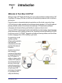
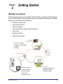
Us e r
M an u a l
Cone Beam 3D +
2D Panoramic Dental
Imaging System
Copyright © Dental Imaging Technologies Corporation 2013, 2014
This manual contains original instructions by Dental Imaging Technologies Corporation for
the safe use of the i-CAT® FLXTM and were originally drafted, approved and supplied in
English. Dental Imaging Technologies Corporation reserves the right to make changes to
both this manual and to the products it describes. Equipment specifications are subject to
change without notice. Nothing contained within this manual is intended as any offer,
warranty, promise or contractual condition, and must not be taken as such.
This document may not, in whole or in part, be copied, photocopied, reproduced, translated,
or reduced to any electronic medium or machine-readable form without prior consent in
writing from Dental Imaging Technologies Corporation.
i-CAT® is a registered trademark of Imaging Sciences International. Other names may be
trademarks of their respective owners.
No part of this document may be reproduced or transmitted in any form or by any means,
electronic or mechanical, for any purpose, without prior written permission of Dental
Imaging Technologies Corporation. Names and data used in examples herein are fictitious
unless otherwise noted. The software program described in this document is provided to its
users pursuant to a license or nondisclosure agreement. Such software program may only
be used, copied, or reproduced pursuant to the terms of such agreement. This manual does
not contain or represent any commitment of any kind on the part of Dental Imaging
Technologies Corporation.
TABLE OF CONTENTS
Chapter 1 - Introduction
Welcome to Your New i-CAT FLX .............................................................................. 1-1
Description .................................................................................................................. 1-2
i-CAT FLX ........................................................................................................................ 1-2
Operator Control Box ...................................................................................................... 1-3
Patient Emergency Stop Control ..................................................................................... 1-4
SmartScan STUDIO Software ......................................................................................... 1-4
Tx STUDIO Treatment Planning Software ...................................................................... 1-4
Chapter 2 - Getting Started
Workflow At A Glance ................................................................................................. 2-1
Scanner Startup .......................................................................................................... 2-2
Power Up ......................................................................................................................... 2-2
Log in ............................................................................................................................... 2-2
Chapter 3 - Scheduling a Patient Exam
Introduction ................................................................................................................. 3-1
Using SmartScan STUDIO Manager to Schedule a Patient Exam ............................. 3-1
Schedule a New Patient for an Exam .............................................................................. 3-1
Schedule an Existing Patient for a New Exam ................................................................ 3-2
Using DEXIS to Schedule a Patient Exam .................................................................. 3-2
Schedule a New Patient for an Exam .............................................................................. 3-2
Schedule an Existing Patient for an Exam ...................................................................... 3-3
Chapter 4 - Selecting a Protocol
Dose Control ............................................................................................................... 4-1
Default Favorites ......................................................................................................... 4-2
Choosing the Best Scan Option for the Patient .......................................................... 4-3
032-0329-EN Rev E
-iii
i-CAT FLX User Manual
Chapter 5 - Positioning the Patient
Patient Positioning For CT Scans - At A Glance ........................................................ 5-1
Patient Positioning For PAN Scans - At A Glance ..................................................... 5-2
Patient Positioning - in Detail ..................................................................................... 5-3
Patient Chair .................................................................................................................... 5-4
Gate ................................................................................................................................. 5-5
Chin Support .................................................................................................................... 5-5
Head Support and Head Strap ........................................................................................ 5-6
Alignment Light ................................................................................................................ 5-8
Scouts and Dry Runs ................................................................................................. 5-9
Instruct Patients Prior to the Scan ............................................................................ 5-10
Chapter 6 - Taking a Scan
Scanning Workflow in SmartScan STUDIO ............................................................... 6-1
Using SmartScan STUDIO Step-by-Step ................................................................... 6-3
Perform a CT Scan .......................................................................................................... 6-3
Perform a PAN Scan ....................................................................................................... 6-5
Build a Custom Protocol .................................................................................................. 6-7
SmartScan STUDIO Details ....................................................................................... 6-8
Choose a Patient Exam ................................................................................................... 6-8
Choose a Protocol ........................................................................................................... 6-9
Choose Type ................................................................................................................. 6-11
Perform a Dry Run ......................................................................................................... 6-12
Perform a CT Scout Scan .............................................................................................. 6-13
Perform a Scan .............................................................................................................. 6-15
Review Exam Images .................................................................................................... 6-16
Perform a PAN Scout Scan ........................................................................................... 6-18
Review PAN Image ....................................................................................................... 6-19
Complete/Incomplete Exam .......................................................................................... 6-20
Build a Custom Protocol Workflow in SmartScan STUDIO ...................................... 6-21
Choose Anatomy ........................................................................................................... 6-22
Choose Resolution ........................................................................................................ 6-24
Choose Dose ................................................................................................................. 6-25
-iv
032-0329-EN Rev E
Table of Contents
Chapter 7 - Opening Images
Introduction ................................................................................................................. 7-1
Locate Exam Images in SmartScan STUDIO Manager ............................................. 7-1
Locate Exam Images in DEXIS .................................................................................. 7-2
Using Tx STUDIO ....................................................................................................... 7-2
Chapter 8 - Calibration and Maintenance
Commonly-Used Utilities ............................................................................................ 8-1
Panel Calibration ............................................................................................................. 8-2
Shutter Calibration ........................................................................................................... 8-3
Reprocessing an Exam .................................................................................................... 8-4
Using Favorites Manager ................................................................................................. 8-4
Routine Cleaning ........................................................................................................ 8-5
Chapter 9 - Shutdown
Scanner Shutdown ..................................................................................................... 9-1
Log out ............................................................................................................................. 9-1
Power Off ......................................................................................................................... 9-1
Appendix A - Safety Guidelines
Intended Use of the Scanner ......................................................................................A-1
Radiation Safety .........................................................................................................A-1
Radiation Protection Measures ........................................................................................A-1
Safety Precautions .....................................................................................................A-2
Safety Devices ............................................................................................................A-3
Warning System ..............................................................................................................A-3
Interlock System ..............................................................................................................A-3
Emergency Stops ............................................................................................................A-4
Appendix B - Status Indicators and Operational Messages
Status Indicators .........................................................................................................B-1
Product Information ....................................................................................................B-1
Operational Messages ................................................................................................B-2
032-0329-EN Rev E
-v
i-CAT FLX User Manual
-vi
032-0329-EN Rev E
Chapter
1
Introduction
Welcome to Your New i-CAT FLX
Welcome to the i-CAT® Family! And thank you for your recent investment in award-winning i-CAT
Cone Beam 3D Imaging. We hope you will have an extraordinary experience with our products
and services.
Praised by owners, esteemed educational organizations and the dental community at large,
i-CAT technology is widely regarded as the cone beam industry standard. i-CAT and its treatment
planning software continue to revolutionize the landscape of 3D dental and maxillofacial
radiography with ultimate efficiency and flexibility for maximum clinical control.
Your new i-CAT FLX was designed to deliver high-definition low-dose imaging, impressive image
quality and clinical control, speed, and ease of use. Proprietary tools such as SmartScan STUDIO
touch screen control, Tx STUDIOTM diagnostic and treatment planning software, and Quick Scan
low-dose imaging put the i-CAT’s flexibility in your hands.
Our goal is that you will
optimize workflow
efficiency with remarkably
rapid scan and
reconstruction rates and
practical office/network
integration.
As with all new clinical
tools, training is
necessary for the practice
to become proficient with
the i-CAT system. In
addition to training with a
certified i-CAT instructor,
we recommend that you
and your clinical team
review this manual for a
thorough understanding
of how to use i-CAT
technology to its potential
in your practice, both
safely and effectively.
032-0329-EN Rev E
1-1
i-CAT FLX User Manual
Description
The following major items comprise the i-CAT FLX:
•
•
•
•
•
•
•
•
•
i-CAT FLX Scanner
Scanner Controller
Touch screen with SmartScan STUDIO software
Keyboard
Operator Control Box
Patient Emergency Stop Control
SmartScan STUDIO Manager software
DEXIS software (optional)
Tx STUDIO Treatment Planning Software
i-CAT FLX
The i-CAT FLX is a Cone Beam Volumetric Tomography and Panoramic scanner used for
dental head and neck applications. It consists of a scanner, scanner controller, touch screen
and keyboard which is suitable for an in-office environment. The scanner is an open design
that allows patients to sit upright during a procedure. An electric powered seat is built into the
scanner for proper patient positioning.
Cone Beam Volumetric Tomography is a medical imaging technique that uses X-rays to
obtain cross-sectional images of the head or neck. Quality of the images depends on the level
and amount of X-ray energy delivered to the tissue. Imaging displays both high-density
tissue, such as bone, and soft tissue. When interpreted by a trained physician, these images
provide useful diagnostic information.
The scanner captures data for 3D skull reconstruction for the following procedures:
•
•
•
•
•
•
•
1-2
Implants
TM Joints
Reconstructed Panoramic
Reconstructed Cephalometrics
Airway / Sinus, etc.
Nerve Canal
PAN - Optional Conventional Digital Panoramic Feature
032-0329-EN Rev E
Introduction
i-CAT® FLXTM with Touch Screen
Operator Control Box
The operator control box must be located outside of the patient environment, and can be
placed on a desktop or wall-mounted. The site layout must provide a means for audio and
visual communication between the operator and patient during scanning.
ON powers the scanner and the POWER indicator lights to show that the scanner is ON.
OFF removes power from the scanner and the POWER indicator goes OFF.
SCAN initiates patient X-ray scanning.
EMERGENCY STOP immediately halts all X-ray and scanning activities.
NOTE: The following indicators are also located on the scanner overhead.
POWER indicator is lit when the scanner is ON.
032-0329-EN Rev E
1-3
i-CAT FLX User Manual
READY indicator is lit when a scan is initiated and the scanner is ready to scan. If the
optional deadman handswitch is installed, this indicator will flash to alert the operator to
press the handswitch.
X-RAY indicator is lit during X-ray exposure.
FAULT indicator lights when a scanner error occurs, such as an X-ray exposure problem
or early release of the optional deadman handswitch.
Patient Emergency Stop Control
The emergency stop control allows the patient to halt all X-ray and scanning
activities by pressing the button.
The emergency stop control can either be hung from the head support
mechanism or held in the patient’s hand as desired.
SmartScan STUDIO Software
SmartScan STUDIO software is used for taking scans on the i-CAT FLX and runs on the
scanner controller. SmartScan STUDIO Manager software is used to enter patient data and
access patient studies. It is loaded on a clinical workstation. Optionally, your site may choose
to use DEXIS software, instead of SmartScan STUDIO Manager, for patient administration.
Tx STUDIO Treatment Planning Software
Tx STUDIO treatment planning software reconstructs 3D volume rendering from images
acquired on the i-CAT FLX. Tx STUDIO is offered for exclusive use with the i-CAT imaging
system, which is manufactured by Imaging Sciences. Tx STUDIO may not be available in all
regions.
1-4
032-0329-EN Rev E
Chapter
2
Getting Started
Workflow At A Glance
i-CAT FLX and the software tools SmartScan STUDIO, DEXIS or SmartScan STUDIO Manager,
and Tx STUDIO enable you to quickly capture patient exam data and view images for treatment
planning. The main steps of the workflow are:
•
•
•
•
•
•
•
Schedule a Patient Exam
Select a Scan Protocol
Position the Patient
Take a Scout Scan to Assess Patient Positioning
Take a Scan
Release the Patient
Open and View Images
•
•
Open and View Images
•
Tx STUDIO
SmartScan STUDIO Manager
or DEXIS
•
•
•
•
•
032-0329-EN Rev E
Select Scan Protocol
Position the Patient
Take a Scout Scan
•
•
Schedule a Patient Exam
SmartScan STUDIO
Manager or DEXIS
Take a Scan
Release the Patient
2-1
i-CAT FLX User Manual
Scanner Startup
The scanner and scanner controller are powered independently, Both must be on to function
properly and are available for use immediately after startup. No warm up is required.
Power Up
1. Power up the scanner: press the ON button on the operator control
box. The POWER indicator on the operator control box and scanner
should light.
2. Power up scanner controller and touch screen: press the power
button on the front of the scanner controller. The log in screen is
displayed.
CAUTION
If the scanner or the scanner controller is powered off, at scanner power up or scanner
controller boot up, when the first scan is initiated (scout or full scan), the i-CAT FLX
performs a reset procedure that may delay the start of first scan.
Log in
To log in to SmartScan STUDIO on the touch screen:
1. Enter your user name and password.
2. Press
2-2
to log in. Scheduled Exams are displayed.
032-0329-EN Rev E
Chapter
3
Scheduling a Patient Exam
Introduction
Depending on your site’s workflow, you may use either SmartScan STUDIO Manager or DEXIS
to schedule patient exams.
Using SmartScan STUDIO Manager to Schedule a Patient Exam
Using SmartScan STUDIO Manager at the clinical workstation, you can schedule a new patient
for an exam or select an existing patient to schedule a new exam. If you need to modify any
patient data after it has been entered and saved, contact your site administrator.
Schedule a New Patient for an Exam
1. At the clinical workstation, start
SmartScan STUDIO Manager.
2. Select New Exam for a New
Patient.
3. Enter data for the patient and exam.
At a minimum, Patient ID and Family
Name must be completed. If a Patient
ID is entered that is already in use, a
Duplicate Patient ID message is
displayed.
NOTE: Entries added to the drop-down
menus are only stored on the local
workstation. They will not display on
another workstation unless they are
added to that workstation.
032-0329-EN Rev E
3-1
i-CAT FLX User Manual
4. Select
. The exam request is sent to SmartScan STUDIO and is displayed in
the Scheduled Exams list on the touch screen.
Schedule an Existing Patient for a New Exam
1. At the clinical workstation, start
SmartScan STUDIO Manager.
2. Select New Exam for an Existing
Patient.
3. Select the patient from the list. Use
the search feature as needed to help
locate the patient.
4. Select the type of new exam, PAN or
CT.
5. Select
. The exam request is
sent to SmartScan STUDIO and is
displayed in the Scheduled Exams
list.
Using DEXIS to Schedule a Patient Exam
If your site uses DEXIS to schedule patient exams, enter patient data in the DEXIS Administration
program. Refer to your DEXIS Imaging Suite Software Manual for additional information.
Schedule a New Patient for an Exam
1. At the clinical workstation, start DEXIS Imaging Suite.
2. on the DEXIS Administration screen, select New Patient.
3. Enter data for the patient and exam.
4. Select OK.
5. Click
3-2
(Extra-oral).
032-0329-EN Rev E
Scheduling a Patient Exam
6. Click
. A pop-up message displays that patient is scheduled for acquisition.
7. Click OK to dismiss pop-up.
Schedule an Existing Patient for an Exam
1. At the clinical workstation, start DEXIS Imaging Suite.
2. On the DEXIS Administration screen, select patient from list or enter search criteria
to locate and select patient.
3. Click
(Extra-oral).
4. Click
. A pop-up message displays that patient is scheduled for acquisition.
5. Click OK to dismiss pop-up.
032-0329-EN Rev E
3-3
i-CAT FLX User Manual
3-4
032-0329-EN Rev E
Chapter
4
Selecting a Protocol
Dose Control
It is important to put the patient’s
health first when selecting a protocol
for the scan. Keep the following in
mind when selecting a protocol:
•
•
•
•
•
Multiple low dose scan settings
provide responsible patientfocused care.
Choose a height to narrow the
image and the applied dose to
only the anatomy of interest.
Preset fields of view simplify the
imaging process to more
efficiently focus on capturing the
anatomy to fit each patient’s
unique case. Target specifically
desired views including maxilla
or mandible single arch, both
arches, and temporomandibular
joints, cephalometric views, and
full skull.
Customize the scan so patients’
anatomy is not exposed outside
the selected field of view.
Capture information critical to
treatment through a clinically
responsible approach that
controls radiation exposure to
the patient.
FOV 8 cm x 8 cm
FOV 16 cm x 4 cm
FOV 16 cm x 6 cm
Maxilla
FOV 16 cm x 6 cm
Mandible
FOV 16 cm x 8 cm
FOV 16 cm x 10 cm
FOV 16 cm x 11 cm
FOV 16 cm x 13 cm
FOV 23 cm x 17 cm
NOTE: Use the PAN 2D panoramic imaging
when CT 3D information is not required.
Disclaimer: The above graphics are only
representations. The actual imaged anatomy
is dependent on the size and position of the
patient being scanned.
032-0329-EN Rev E
4-1
i-CAT FLX User Manual
Default Favorites
Default protocol favorites are pre-loaded in SmartScan STUDIO for CT and PAN scans.
Volume Size
Voxel
Scan Time
DAP
(Diameter x Height)
(mm)
(Seconds)
(mGy2cm2)
3D Ceph
16 x 13
0.3
8.9
623.9
3D Ceph (Quick Scan)
16 x 13
0.3
4.8
349.4
3D Ceph (Quick Scan+)
16 x 13
0.3
4.8,
reduced mA
99.2
Arches - small
8x8
0.3
8.9
239
Arches - small (Quick Scan)
8x8
0.3
4.8
134.8
Arches - small (Quick Scan+)
8x8
0.3
4.8
reduced mA
40
Arches/TMJ
16 x 11
0.3
8.9
543
Arches/TMJ (Quick Scan)
16 x 11
0.3
4.8
301
Arches/TMJ (Quick Scan+)
16 x 11
0.3
4.8
reduced mA
86.5
Both Arches
16 x 8
0.3
8.9
388.9
16 x 6
biased for mandible
0.3
8.9
291.4
16 x 6
biased for maxilla
0.3
8.9
302.9
CT Favorite Name
Mandible
Maxilla
Expanded 3D Ceph
23 x 17
0.3
17.8
877.6
SureSmile Dentition/Full
(acquisition and reconstruction)
16 x 13
0.25
26.9
1257
Second reconstruction follows at:
(no manual reprocessing required)
16 x 8
0.2
n/a
n/a
SureSmile Dentition/Full (Quick Scan)
(acquisition and reconstruction)
16 x 13
0.25
14.7
659.9
Second reconstruction follows at:
(no manual reprocessing required)
16 x 8
0.2
n/a
n/a
SureSmile Dentition
16 x 8
0.2
26.9
797.4
SureSmile Dentition (Quick Scan)
16 x 8
0.2
14.7
444.3
4-2
032-0329-EN Rev E
Selecting a Protocol
Scan Time
DAP
Projection
kVp / mA
(Seconds)
(mGy2cm2)
Panoramic
Standard
94 / 5
20.0
146.4
Panoramic - small
Standard
84 / 5
18.3
91
PAN Favorite Name
NOTE:
• 8 x 8 scans capture a smaller field of view. Use a larger volume size when the
anatomical area being scanned is greater than 8 x 8.
• You can build a custom protocol for a CT scan and save it as a favorite, as described in
Build a Custom Protocol Workflow in SmartScan STUDIO.
Choosing the Best Scan Option for the Patient
To acquire the best scans, select the appropriate scan protocols and options for the patient and
the case. Use the following guidelines when selecting scan options:
•
•
•
•
•
•
A longer scan time results in better image detail, but more dose to the patient. No
patient movement will ensure best results.
A shorter scan time results in less dose to the patient.
Collimate down whenever possible for optimal image quality.
Use a Quick Scan option if the patient is prone to movement during the scan.
One option does not fit all: keep dose as low as reasonably achievable.
Always choose scan options before positioning the patient.
032-0329-EN Rev E
4-3
i-CAT FLX User Manual
i-CAT Scan Type
Height (cm)
Resolution
(voxel size)
Scan Time
(seconds)
Follow Up
Progress Records
TMJ
3rd Molars
Children
Prone to Movement
Cephalometrics
13, 11, 10,
8, 6, 4
0.4, 0.3*
4.8
Standard
Implants
3rd Molars
Cephalometrics
13, 11, 10,
8, 6, 4
0.4, 0.3*
8.9
Quick Scan HD
HD
(Hi Resolution)
Endo
Root Fractures
Pathology
Impactions
Supernumerary
Periodontal Conditions
13, 11, 10,
8, 6, 4
0.25, 0.2*,
0.125
14.7
26.9
Expanded 3D
Ceph
Cephalometrics for Large Skulls
Orthognathic Surgery
0.3 Enhanced*
17.8
0.3, 0.4
8.9
Quick Scan+
Quick Scan
(Lower Dose)
17
*suggested option
NOTE: See the i-CAT website for information about the use of 3rd Party software with the i-CAT.
4-4
032-0329-EN Rev E
Chapter
5
Positioning the Patient
Patient Positioning For CT Scans - At A Glance
Position the patient for minimal movement and maximum image quality. To prevent patient
movement:
•
•
•
•
When possible, use the head support, strap and chin cup.
Stabilize patient’s feet with a foot stool if needed.
If shoulder clearance is a concern, lower the chair elevation and tilt chin up.
Do a Dry Run to test for shoulder clearance.
1. Adjust chair height.
Chair seat is typically
in top slot. Set
elevation with
horizontal laser light
at patient’s smile line.
2. Close the gate.
3. Ensure the patient’s
chin is sitting
comfortably yet firmly
in the chin cup.
032-0329-EN Rev E
Tips:
If Gate won’t close:
• Use the head support/strap
without the chin cup. Keep gate
open and remove metal chin
support mechanism.
OR
• Take out head support and use
just the chin cup.
OR
• Slide patient slightly forward
allowing room to lean back into
scanner with chair in upper slots.
4. Secure patient in
head support and
attach head strap
around forehead.
For Orthodontics:
• Use just head support/strap so
the chin cup is not visible.
Remove metal chin support
mechanism.
5. Adjust tilt of jaw.
Occlusal plane
should be horizontal.
External reference:
tragus-ala line
horizontal.
Instruct Patient Prior to Scan
• Do not swallow during the scan.
• Slow shallow breaths during the
scan.
• Close eyes during the scan.
• Stay as still as possible.
5-1
i-CAT FLX User Manual
Patient Positioning For PAN Scans - At A Glance
1. Place chair in the upper slots so that chair back does not impede
patient’s ability to sit with an erect posture.
2. If head support is installed, loosen locking knob and remove head
support. Slide PAN head holder into place and tighten locking knob.
Temple
Pads
Locking
Knob
Narrow
Edge
3. Insert the narrow edges of bite tip down into bite tip holder uprights.
Turn the bite tip a ¼ turn to lock into place.
4. Insert the chin rest and bite tip holder into the positioning block.
5. Seat the patient in the chair with an erect posture. The neck must be
stretched up and as straight as possible to avoid the spine getting in
the view. Close the gate.
6. Adjust chair height so that the
patient’s chin is on the chin rest,
but erect posture is maintained.
Patient Tilted
Downward
10o
Horizontal Laser
Occlus
al Plan
Chin Rest
Bite Tip
Holder
e
7. Tilt the patient’s head downward
so that the occlusal plane forms
roughly a 5o to 10o angle to the
horizontal laser line.
8. Use the sagittal laser (front
center laser) to ensure that the
patient is centered and facing
straight forward.
9. Instruct patient to bite in the groove of the bite tip and to close lips around the bite tip as if using a straw.
Adjust height of bite tip holder as needed.
10. Close head holder arms so temple pads fit to patient’s temples. If necessary, loosen head support knob
and adjust head holder forward or backward as needed to fit head holder to patient. Tighten knob.
11. Instruct patient to swallow and hold, put the tongue to the roof of the mouth and hold for the duration of
the exposure.
5-2
032-0329-EN Rev E
Positioning the Patient
Patient Positioning - in Detail
Positioning the patient properly and minimizing patient movement are the keys to optimal scan
results. Several scanner features can be used to assist with patient positioning and are detailed
in the following paragraphs.
The figure below shows the location of these features and the order in which they are generally
used to position a patient.
5. Use Laser Lights to
check positioning
4. Adjust Head Support and
use Head Strap as needed
2. Close Gate
1. Adjust Chair
Height
032-0329-EN Rev E
3. Adjust Chin
Support and
Chin Cup as
needed
5-3
i-CAT FLX User Manual
Patient Chair
Patient Align
Buttons
Sensor Panel
Gate
Chair
Mounting
Slots
There are two sets of mounting slots for the chair. Use the following table as a guideline for
initial placement of the chair:
Patient Height
Chair Position
6’ 0” and Taller
Lower Slots
Under 6’ 0”
Upper Slots
NOTE: Ensure chair is fully seated in slots to prevent movement when chair is used.
The chair height can be adjusted using the PATIENT ALIGN buttons on Patient Alignment
Panel. These controls allow movement of the chair, up (▲) and down (▼), to facilitate patient
alignment with the chin support.
Other factors to consider when positioning the patient in the chair are:
5-4
•
Very tall patients (over 7’) may be required to slide down in the chair to gain the
proper alignment with the sensor panel.
•
Shorter adults or children may require a foot stool to stabilize the feet.
•
Children may need a booster seat to gain proper alignment.
032-0329-EN Rev E
Positioning the Patient
Gate
The gate swings open to allow patient seating. The patient should be seated facing forward
with hands in lap.
NOTE: Closing the gate creates a pinch point. Keep hands and other body parts clear when
closing gate.
Close gate prior to scanning, making sure the magnet is secured in its locked position. If gate
will not close:
•
Move head support to the rearmost position. With chair in the upper slot, have
patient slide forward in seat and then lean back into scanner.
•
Use head strap without the chin cup.
•
Keep gate open and remove entire chin support.
Chin Support
The chin support is comprised of several
components to help facilitate correct
positioning of the patient for CT scans.
For most studies, the chin cup should be
aligned with the bottom of the sensor
panel.
Chin Cup
To Adjust the Chin Cup:
1. Insert the slide in the slide block.
2. Insert the chin cup.
3. Raise or lower the chin cup to
desired height, then tighten
adjusting knob to secure in
place.
032-0329-EN Rev E
Slide
Adjusting Knob
5-5
i-CAT FLX User Manual
Head Support and Head Strap
Head Support
Locking Knob
Head Support
Head Support
Adjusting Knob
The head support slides forward or backward for head stabilization. The patient’s head
should be supported firmly between the chin cup and head support. Loosen the head support
adjusting knob, then use the knob to slide the head support forward or backward to move it
into the proper position. When positioned, tighten knob.
A head strap can also be used to help stabilize the head. A velcro head restraint kit comes
with the scanner. For initial use of the head strap, the velcro pads in the kit must be attached
to the back of the head support.
For PAN scans, use the PAN head holder to support the patient’s head.
5-6
032-0329-EN Rev E
Positioning the Patient
To Install Velcro Pads:
Velcro Pads
1. Loosen the locking knob and remove the head
support.
2. Attach pads and, if necessary, trim to fit.
3. Insert head support and tighten locking knob.
To Use the Head Strap:
1.
Attach one end of the head strap to one side of
the head support.
2. Wrap head strap around patient’s forehead and
secure to other side of head support.
For scans that are specific to TMJ or orthodontics, only the head support and head strap
should be used. It is recommended that the chin support not be used because it can affect
the Condylar position in Fossa and interfere with soft tissue at the chin.
NOTE: The gantry does not move into position for a selected protocol until the Scan button
is pressed. The crosshair laser may not be beneficial to patient positioning until a Scout or
Scan has been performed for the selected protocol.
032-0329-EN Rev E
5-7
i-CAT FLX User Manual
Alignment Light
Alignment
Light Button
Sagittal Laser Light
Crosshair Laser Light
NOTE: Laser beams can cause optical damage. Do not stare into the laser beam. Instruct the
patient to avoid looking into the beam. The use of optical instruments such as eyeglasses with
large diopter or mirrors, increase eye hazard with this product.
The Alignment Light button projects a horizontal and vertical crosshair laser light from the
side of the scanner and a vertical Sagittal laser light down the center of the chair to assist with
patient positioning. Pressing the button turns on the laser alignment lights for two minutes, or
until the button is toggled off.
In general, the alignment lights should be positioned as follows:
•
Horizontal light - Position at the Occlusal Plane between the lips (smile line).
•
Vertical light - Position at 1.5 inches in front of condyles.
•
Sagittal light - Typically runs down the center of the patient’s head and the chin
support.
The position of the horizontal alignment light may vary slightly depending on the patient’s
position and the selected height of scan. Final position of the vertical alignment light may also
vary, depending on patient’s anatomy and if the full soft tissue profile is desired.
5-8
032-0329-EN Rev E
Positioning the Patient
Occlusal Plane Flat,
Frankfurt Plane tilted
up slightly.
Position of Alignment Lights:
Horizontal: Occlusal plane between the lips.
Vertical: 1.5 inches in front of condyle (chin support adjusted to acquisition position).
Scouts and Dry Runs
NOTE: Scout scans and Dry Runs are described in detail in the Taking a Scan chapter.
It is recommended that a Scout scan be performed to verify patient positioning. A Scout scan
exposes the patient to a fraction of a second of radiation, but provides an image that can be used
to verify that the patient is positioned to capture desired field of view (FOV).
A Dry Run is recommended for patients who want a demonstration of the machine motion, and
to check shoulder clearance. A Dry Run simply rotates the gantry in the exact manner that is
required for the selected protocol, but does not expose the patient to any radiation.
032-0329-EN Rev E
5-9
i-CAT FLX User Manual
Instruct Patients Prior to the Scan
Inform patients of what to expect during a scan so that they are prepared and avoid movement
during the scan.
•
•
The gantry rotates around the head during the scan.
The exposure buzzer sounds for the duration of the rotation.
Instruct patients to perform the following prior to or during the scan:
•
Remove all metal objects from the shoulders up, including glasses.
•
Place hands in lap or hold on to the bottom of chair.
•
Do not swallow during scan.
•
Breathe through nose during scan.
•
Stay as still as possible until the gantry has finished moving.
•
Close eyes during scan.
•
Keep teeth gently together and in same position.
NOTE: Always use a lead apron on the patient when taking a scan.
5-10
032-0329-EN Rev E
Chapter
6
Taking a Scan
Scanning Workflow in SmartScan STUDIO
SmartScan STUDIO uses a simple touch screen interface that enables you to quickly take a scan
for a patient exam. The typical workflow guides you through the following steps.
Step
Purpose
1
Choose a Patient Exam
2
Choose a Protocol
3
Choose Type
4a
Perform a Dry Run (optional)
032-0329-EN Rev E
Display
6-1
i-CAT FLX User Manual
4b
Perform a CT Scout Scan
OR
Perform a PAN Scout Scan
4c
Perform a Scan
5
Review Exam Images
OR
Review PAN Image
6
Complete/Incomplete Exam
6-2
032-0329-EN Rev E
Taking a Scan
Using SmartScan STUDIO Step-by-Step
Use the following step-by-step instructions for the desired workflow:
•
•
•
Perform a CT Scan
Perform a PAN Scan
Build a Custom Protocol
Perform a CT Scan
1. In SmartScan STUDIO, select exam entry in scheduled exams list.
2. Press
to access protocols.
3. Select desired protocol.
4. Review scan protocol information in header.
5. Position patient for scan. Refer to Patient Positioning For CT Scans - At A Glance.
6. Press
to continue.
7. Select
(scout scan) and press
to continue. The scanner initializes.
8. Instruct the patient to hold still, swallow before the scan, take shallow breaths during
the scan and close his/her eyes so as not to follow the gantry during the scan.
9. When prompted, press the Scan button on the operator control box.
An audible alarm is sounded and the X-ray ON light is illuminated during radiation
exposure. The scanner acquires the data and creates the images.
CAUTION
If the optional deadman handswitch is installed on the scanner, press and hold
handswitch before pressing the Scan button, and continue to hold handswitch down for
the duration of the exposure (X-ray light on). Early release of the handswitch stops the
exposure and the Fault light turns on. The patient will have to be re-scanned.
10. Review scout image. To ensure the scan captures the entire anatomy desired, the
anatomy should appear within a 1 cm border of the edge of the scout scan. Use
visualization controls as needed.
032-0329-EN Rev E
6-3
i-CAT FLX User Manual
11. If patient position is not correct, re-position patient or use Front/Back slider control
or up/down buttons to move panel into proper position.
Press
and repeat steps 7 - 10 to perform another scout.
12. If patient position is correct for scan, press
13. Select
(full scan) and press
.
to continue. The scanner initializes.
14. Instruct the patient to hold still, swallow before the scan, take shallow breaths during
the scan and close his/her eyes so as not to follow the gantry during the scan.
15. When prompted, press the Scan button on the operator control box.
An audible alarm is sounded and the X-ray ON light is illuminated during radiation
exposure. The scanner acquires the data and creates the images.
CAUTION
If the optional deadman handswitch is installed on the scanner, press and hold
handswitch before pressing the Scan button, and continue to hold handswitch down for
the duration of the exposure (X-ray light on). Early release of the handswitch stops the
exposure and the Fault light turns on. The patient will have to be re-scanned.
16. Review image to ensure adequate quality. The view on the right side of the screen
rotates to provide a quick check of the image. Use controls as needed to aid with
visualization.
17. Press
to continue.
18. If CT scan is not acceptable, reposition and re-scan the patient.
19. If CT scan is acceptable:
6-4
•
Ensure scanner is reset.
•
Remove the head strap and move head support back.
•
Ask patient to sit back out of chin cup, open the gate gently and release the
patient.
032-0329-EN Rev E
Taking a Scan
Perform a PAN Scan
1. Prepare the scanner for a PAN scan. Refer to Patient Positioning For PAN Scans At A Glance.
2. In SmartScan STUDIO, select exam entry in scheduled exams list.
3. Press
to access protocols.
4. Select a
protocol.
5. Position patient for scan. Refer to Patient Positioning For PAN Scans - At A Glance.
6. Select
(scout scan) and press
to continue. The scanner initializes.
7. Instruct the patient to swallow and hold, put the tongue to the roof of the mouth and
hold for the duration of the exposure.
8. When prompted, press the Scan button on the operator control box.
An audible alarm is sounded and the X-ray ON light is illuminated during radiation
exposure. The scanner acquires the data and creates the images.
CAUTION
If the optional deadman handswitch is installed on the scanner, press and hold
handswitch before pressing the Scan button, and continue to hold handswitch down for
the duration of the exposure (X-ray light on). Early release of the handswitch stops the
exposure and the Fault light turns on. The patient will have to be re-scanned.
9. Review scout scan to ensure the following:
•
Verify patient is positioned properly at a 10o
angle. Press and drag the button for the
Occlusal (yellow) plane line to position it over
the patient’s Occlusal plane on the scout scan.
The line should roughly align from the back of
the smile line to the point where the patient is
biting on the bite tip. Use the slide controls to
adjust the brightness and contrast buttons as
needed.
032-0329-EN Rev E
6-5
i-CAT FLX User Manual
•
Ensure bite tip is horizontal and bite tip holder is vertical.
•
Ensure patient’s lips are together and both upper and lower teeth are in notches
of the bite tip.
•
Ensure chin is not cut off or too low. Leave a 5 mm gap between the lower
border of the chin and border of the scout scan.
10. If patient position is not correct, use Patient Alignment Panel buttons to lower or raise
the chair. To lower the degree of the angle, lower the chair. To raise the degree of the
angle, raise the chair. You may need to adjust the head holder and bite tip holder
appropriately.
Press
and repeat steps 6 - 9 to perform another scout.
11. If patient position is correct for scan, press
12. Select
(full scan) and press
.
to continue. The scanner initializes.
13. Instruct patient to close lips around the bite tip as if using a straw, swallow and hold,
put the tongue to the roof of the mouth and hold for the duration of the exposure.
14. When prompted, press the Scan button on the operator control box.
An audible alarm is sounded and the X-ray ON light is illuminated during radiation
exposure. The scanner acquires the data and creates the images.
CAUTION
If the optional deadman handswitch is installed on the scanner, press and hold
handswitch before pressing the Scan button, and continue to hold handswitch down for
the duration of the exposure (X-ray light on). Early release of the handswitch stops the
exposure and the Fault light turns on. The patient will have to be re-scanned.
15. Review image to ensure adequate quality. Use controls as needed to aid with
visualization.
16. Press
to continue.
17. If PAN scan is not acceptable, reposition and re-scan the patient.
6-6
032-0329-EN Rev E
Taking a Scan
18. If PAN scan is acceptable:
•
Ensure scanner is reset.
•
Press the Push to Release lever on the head holder to open the arms. Do not
manually force arms open. Open gate.
•
Ask patient to sit back out of bite stick and chin rest, open the gate gently and
release the patient.
•
If you are done performing PAN scans, remove head holder and re-install the
head support.
Build a Custom Protocol
Refer to Using Favorites Manager for information about managing protocol favorites.
1. Access protocol screen and select
.
2. From filmstrip, select anatomy to be captured. Press
3. Select resolution for the scan. Press
.
.
4. Select dose for the scan. Options available vary based on selections made in the two
previous steps.
5. Press
. On dialog box, enter a unique name for the protocol. Press
to save custom protocol. Default values for acquisition type will be used.
NOTE: To save a scout scan as the acquisition type, select
follow step 5 above to save the protocol.
032-0329-EN Rev E
on Choose Type, then
6-7
i-CAT FLX User Manual
SmartScan STUDIO Details
Choose a Patient Exam
Select a patient exam from the exam list.
The list shows all exams currently scheduled. Exam requests are scheduled on a clinical
workstation using SmartScan STUDIO or DEXIS.
Touch and drag to scroll through the list as needed and select an exam entry.
Continue with selected exam.
Go to Utilities.
Note: This is the only user access point to the Utilities menu.
Exit the application. A confirmation dialog box results.
to confirm exit or
6-8
to cancel and return.
032-0329-EN Rev E
Taking a Scan
Choose a Protocol
Select a protocol to use for the exam. Touch and drag to scroll through the options as needed.
The scan parameters defined for the protocol are displayed in the header.
The protocol menu includes both default and custom protocols. Default protocols are
provided with SmartScan STUDIO. Custom protocols are user-defined protocols created
using the Build a Custom Protocol Workflow in SmartScan STUDIO.
Header Parameter
Definition
Logged in as
User name of current user.
Patient Name
Name and date of birth of patient selected.
Total Exam DAP
Total absorbed dose of all scouts and scans taken during
this patient’s current exam session in DAP (dose area
product) mGy*cm2 (milliGray centimeters squared).
Modality
Type of exam requested: PAN or CT.
Volume Size (CT)
Projection (PAN)
Diameter and height of scan in centimeters.
Standard or Small
032-0329-EN Rev E
6-9
i-CAT FLX User Manual
Voxel Size (CT)
Patient Size (PAN)
0.4, 0.3, 0.25, 0.2, or 0.125 in millimeters.
Large or Small
Scan Time
Total scan time in seconds. For CT scans, X-rays are
pulsed. Patient is not exposed to X-rays for the entire scan
time.
Protocol Name
Name of protocol selected.
Exposure Time
Length of time in seconds of the exposure.
kV
KiloVolt setting for the scan.
mA
MilliAmpere setting for the scan.
Scan DAP
Scout DAP
Dry Run DAP
Scan, scout, or dry run dose in DAP mGy*cm2.
The DAP value for a dry run is 0.
Continue with selected protocol.
Go back and select another exam. A confirmation dialog box
results.
to confirm or
to cancel and return to current exam.
Create a custom protocol for a CT scan. Refer to Build a Custom
Protocol Workflow in SmartScan STUDIO.
6-10
032-0329-EN Rev E
Taking a Scan
Choose Type
Select a scan type.
Dry Run (not available for PAN scans or Utilities) - rotates the
gantry in the exact manner that is required for the selected
protocol, but does not expose the patient to any radiation. Use a
Dry Run to give the patient a demonstration of the machine motion
and/or to check shoulder clearance. DAP value for a dry run is 0.
Scout Scan - preview scan that exposes the patient to a small
amount of radiation. It is used to check that the patient is properly
positioned to capture the desired anatomy for the scan. DAP value
for the scout scan is displayed in the header.
Full Scan - full scan used for diagnostic purposes. This can be
either a CT scan or a PAN scan. DAP value for the scan is
displayed in the header.
032-0329-EN Rev E
6-11
i-CAT FLX User Manual
Continue with selected type. The scanner initializes.
You have two minutes to press Scan on the operator control box
before the scanner times out. If the scanner times out, the scan is
incomplete. Begin the workflow again.
Go back to select a different protocol.
Perform a Dry Run
Position patient for the scan. Instruct the patient that the gantry will rotate to check for
clearance, but no images will be acquired. DAP value is 0 for a dry run.
Continue to Choose Type.
Cancel scan and exit workflow. Dry Run is complete.
6-12
032-0329-EN Rev E
Taking a Scan
Perform a CT Scout Scan
Take a scout scan to check for proper patient positioning to ensure desired anatomy will be
captured.
Instruct the patient to hold still, swallow before the scan, take shallow breaths during the scan
and close his or her eyes.
If multiple scouts are taken during a patient session, the cumulative DAP value is displayed
in the header under Total Exam DAP.
To ensure the scan captures the entire anatomy desired, the anatomy should appear within
a 1 cm border of the edge of the scout scan.
Continue to Choose Type.
Cancel scan and exit workflow. Scout scan is complete.
Adjusts the shutter position to move the field of view up or
down to help capture intended anatomy. Buttons are active
for scan protocols of 10 cm height or less.
032-0329-EN Rev E
6-13
i-CAT FLX User Manual
Center line indicates center of X-ray beam. Line is not user
interactive.
Page through scout scans captured during current patient
session.
Save custom scan parameters (anatomy, resolution, dose,
and acquisition type). On dialog box, enter a unique name
for the protocol.
to save custom protocol or
to cancel.
Moves panel back or front to assist with positioning of the
patient for the scan. Slider position indicates where the
next scan will be taken. Arrow indicates panel position
when a scout image is captured. Useful when multiple
scouts are captured as it provides a point of reference for
adjustment.
Adjusts brightness of image.
Adjusts contrast of image.
6-14
032-0329-EN Rev E
Taking a Scan
Perform a Scan
Take a full scan when patient is properly positioned.
Instruct the patient to hold still, swallow before the scan, take shallow breaths during the scan
and close his or her eyes.
Displays when a HD or Standard CT scan is acquired. Toggle to
view first and last frame of scan to check for patient movement.
Frames are the same if the patient did not move. Consider re-scan
if movement is detected.
Cancel image processing. Displays until image creation is
complete. Patient has been exposed to X-rays.
032-0329-EN Rev E
6-15
i-CAT FLX User Manual
Review Exam Images
Review image to ensure a quality scan was acquired.
Use controls as needed to help with visualization.
Continue to Complete dialog box with
options for next scan.
Adjusts brightness of image directly above
slider. Individual controls are provided for
left and right image display.
Adjusts contrast of image directly above
slider. Individual controls are provided for
left and right image display.
Toggle to display or hide axial indicator
line.
6-16
032-0329-EN Rev E
Taking a Scan
MIP View (maximum-intensity projection).
Initial view after scan completes.
Left Viewport
Axial
Right Viewport
MIP
Right view rotates continuously from
-90o to +90o position to provide a quick
check of the image. Touch image to stop
the rotation (cannot be restarted).
Image can be rotated manually with a
swipe.
Axial Slice
MIP Rotation
Drag indicator line in right viewport up or
down to view axial slices in left viewport.
Select Coronal View.
Left Viewport
Right Viewport
Axial
Coronal
Axial Slice
Coronal Slice
Drag indicator line in right viewport up or
down to view axial slices in left viewport.
Drag indicator line in left viewport up or
down to view coronal slices in right
viewport.
Select Sagittal View.
Left Viewport
Axial
Right Viewport
Sagittal
Drag indicator line in right viewport up or
down to view axial slices in left viewport.
Drag indicator line in left viewport left or
right to view sagittal slices in right viewport.
Axial Slice
032-0329-EN Rev E
Sagittal Slice
6-17
i-CAT FLX User Manual
Perform a PAN Scout Scan
Take a PAN scout scan to check for proper patient positioning to ensure desired anatomy will
be captured.
Instruct the patient to close lips around the bite tip as if using a straw, swallow and hold, put
the tongue to the roof of the mouth and hold for the duration of the exposure.
If multiple scouts are taken during a patient session, the cumulative DAP value is displayed
in the header under Total Exam DAP.
Use yellow occlusal plane line control to help check for patient positioning.
Continue to Choose Type.
Cancel scan and exit workflow. Scout scan is complete.
Drag the yellow occlusal plane line control to position it
over the patient’s occlusal plane on the scout scan. The
line should roughly align from the back of the smile line to
the point where the patient is biting on the bite tip.
Page through scout scans captured during current patient
session.
6-18
032-0329-EN Rev E
Taking a Scan
Adjusts brightness of image.
Adjusts contrast of image.
Review PAN Image
Review PAN image to ensure a quality scan was acquired.
Use controls as needed to help with visualization.
Continue to Complete dialog box with options for next scan.
Adjusts brightness of image directly above slider. Individual
controls are provided for left and right image display.
Adjusts contrast of image directly above slider. Individual
controls are provided for left and right image display.
032-0329-EN Rev E
6-19
i-CAT FLX User Manual
Complete/Incomplete Exam
Complete - Acquire workflow is completed for the exam.
Incomplete - Acquire workflow did not complete for the exam.
New Exam - Go to Scheduled Exams and select another exam.
Confirmation dialog box results.
to confirm or
to cancel.
Same Exam - Continue with existing exam and return to the
protocol menu.
Close exam and logout. Exam is removed from Scheduled Exams
list.
to confirm or
6-20
to cancel.
032-0329-EN Rev E
Taking a Scan
Build a Custom Protocol Workflow in SmartScan STUDIO
The Custom Protocol workflow enables you to build a custom protocol for CT scans by selecting
the anatomy (diameter and height), resolution (voxel size), and dose for the protocol.
Press
on the protocol menu to start building a custom protocol.
Step
Purpose
1
Choose Anatomy
2
Choose Resolution
3
Choose Dose
032-0329-EN Rev E
Screen
6-21
i-CAT FLX User Manual
Choose Anatomy
Select anatomy for the scan protocol. The Volume Size header parameter highlights the
selected value.
Scan DAP is not displayed until the dose is selected on the Choose Dose screen.
6-22
Anatomy
Diameter x Height (cm)
Both Arches - small
8x8
Single Arch - small
16 x 4
Mandible
16 x 6 mandible
Maxilla
16 x 6 maxilla
032-0329-EN Rev E
Taking a Scan
Both Arches
16 x 8
Arches/TMJ - small
16 x 10
Arches/TMJ
16 x 11
3D Ceph
16 x 13
Expanded 3D Ceph
23 x 17
Continue to Choose Resolution.
Go back to Protocol menu.
032-0329-EN Rev E
6-23
i-CAT FLX User Manual
Choose Resolution
Select resolution for the scan. Resolution options available depend on the anatomy chosen.
The Voxel Size header parameter highlights the selected value.
Scan DAP is not displayed until the dose is selected on the Choose Dose screen.
Select voxel size (in
millimeters).
0.4
0.3
0.25
0.2
0.125
Continue to Choose Dose.
Go back to Choose Anatomy.
6-24
032-0329-EN Rev E
Taking a Scan
Choose Dose
Select the dose for the protocol.
The Scan Time, Exposure Time, kV, mA, and Scan DAP header parameters highlight the
resulting values based on the options selected on all custom protocol screens.
Options available vary based on custom protocol selections.
For 8cm and 16cm Diameter, 0.3 and 0.4 voxel scans:
Quick Scan+ - lowest dose scan mode. Uses a half rotation and reduced mA. Image clarity
is lower than Quick Scan.
Quick Scan - lower dose than standard mode. Uses a half rotation. Image clarity is generally
lower than standard mode.
Standard - uses standard time settings for maximum image clarity.
For 8cm and 16cm Diameter, 0.125, 0.2 and 0.25 voxel scans:
Quick Scan HD - uses a shorter exposure time and delivers less dose to patient than HD
scan, but at a lower resolution.
HD - uses longer exposure time settings for high resolution image quality.
For 23cm Diameter, 0.3 and 0.4 voxel scans:
Standard - uses standard exposure time settings.
Enhanced - uses longer exposure time settings for maximum image quality.
032-0329-EN Rev E
6-25
i-CAT FLX User Manual
Save selected scan parameters (anatomy, resolution, dose, and
acquisition type) as a custom protocol. On dialog box, enter a
unique name for the protocol.
to save custom protocol or
to cancel.
Continue to Choose Type.
Go back to Choose Resolution.
6-26
032-0329-EN Rev E
Chapter
7
Opening Images
Introduction
Depending on your site’s workflow, you may use either SmartScan STUDIO Manager or DEXIS
to access patient exam images.
Locate Exam Images in SmartScan STUDIO Manager
1. At the clinical workstation, start
SmartScan STUDIO Manager.
2. Select Exam List.
3. Locate the patient from the list. Use
the search feature as needed to help
find the patient.
4. Select arrow to expand the exam data
for the patient, then select the exam.
5. Double-click the desired exam.
Modalities are:
CT - Full CT (3D) scan
RAW_CT - Raw data from CT scan
(cannot be opened in Tx STUDIO)
DX - Scout scan (2D image)
PX - PAN scan (2D image)
6. Exam opens in Tx STUDIO. For 2D
images, the images can be viewed,
but the 3D functions are turned off.
032-0329-EN Rev E
7-1
i-CAT FLX User Manual
Locate Exam Images in DEXIS
If your site uses DEXIS, enter patient data in the DEXIS Administration program. Refer to your
DEXIS Software Manual for additional information.
1. In DEXIS Imaging Suite, locate patient, then click
to open the Extra-oral display.
2. Double-click the i-CAT box to start Tx STUDIO and load patient
exam.
3. View scan in Tx STUDIO.
Using Tx STUDIO
Refer to Tx STUDIO Reference Manual for information on using Tx STUDIO.
7-2
032-0329-EN Rev E
Chapter
8
Calibration and Maintenance
Commonly-Used Utilities
The Utilities menu contains options for running various calibration and quality assurance tests, as
well as options for reprocessing an exam and managing protocol favorites that are user-created.
In SmartScan Studio, press
to access the Utilities menu. The following are the most
commonly-used options. Refer to the i-CAT FLX Technical Guide for information on the other
Utilities menu options.
Option
Description
PanelCal
Panel calibration should be performed once a week.
ShutterCal
Shutter calibration should be performed once a week to
ensure optimal image quality.
Reprocess Exam
Reprocess an acquired scan for which there is raw data
available on the scanner controller. Exams are reprocessed
using the same settings with which they were acquired.
Favorites Manager
Options to manage protocol favorites.
CAUTION
If the optional deadman handswitch is installed on the scanner, press and hold
handswitch before pressing the Scan button, and continue to hold handswitch down for
the duration of the exposure (X-ray light on). Early release of the handswitch stops the
exposure and the Fault light turns on. The patient will have to be re-scanned.
032-0329-EN Rev E
8-1
i-CAT FLX User Manual
Panel Calibration
It is recommended that Panel Cal be performed once a week.
The Panel Cal is performed in both landscape and portrait positions
for 4 x 4 and 2 x 2 resolutions. Several tests run as part of the panel
calibration. A pie chart displays status.
Run Panel Calibration
1. Select PanelCal.
2. Ensure the field of view on the scanner is clear.
3. Press
. The scanner initializes.
4. When prompted, press the Scan button on the operator control box. An audible alarm
is sounded and the X-ray ON light is illuminated during radiation exposure.
5. You will be prompted to press the Scan button for each test.
NOTE: The panel will rotate to the portrait position at the start of the portrait tests.
6. When Panel Cal is complete, Calibration Complete is displayed.
7. Press
to display Complete screen and select another option.
Panel Calibration Failure
If the calibration fails, the following message is displayed:
Panel Calibration Processing Failure
Press
to exit.
Check that the field of view is clear of all objects and that there are no obstacles to the
rotation of the gantry. Re-run Panel Cal.
If failure persists, contact Technical Support.
8-2
032-0329-EN Rev E
Calibration and Maintenance
Shutter Calibration
It is recommended that Shutter Cal be performed once a week to
ensure optimal image quality. This calibration is also necessary if
a mechanical adjustment is made to the beam limiter or if image
quality has degraded.
The Shutter Cal runs several tests in both landscape and portrait
positions. A pie chart displays status.
Run Shutter Calibration
1. Select ShutterCal.
2. Ensure the field of view on the scanner is clear.
3. Press
. The scanner initializes.
4. When prompted, press the Scan button on the operator control box. An audible alarm
is sounded and the X-ray ON light is illuminated during radiation exposure.
5. You will be prompted to press the Scan button for each test.
NOTE: The panel will rotate to the portrait position at the start of the portrait tests.
6. When Shutter Cal is complete, Calibration Complete is displayed. Thumbnail
images of each Shutter Cal test are available to view.
7. If desired, select a thumbnail to view.
8. Press
to display Complete screen and select another option.
Shutter Calibration Failure
If the calibration fails, the following message is displayed:
Shutter Calibration Processing Failure
Press
to exit.
Check that the field of view is clear of all objects and that there are no obstacles to the
rotation of the gantry. Re-run Shutter Cal.
If failure persists, contact Technical Support.
032-0329-EN Rev E
8-3
i-CAT FLX User Manual
Reprocessing an Exam
The Reprocess Exam list contains acquired scans for which there is raw data available on the
scanner controller. Raw data is maintained on the scanner controller for a short period of time.
The exam data is deleted from the scanner controller only when the data has been moved
successfully.
It may be necessary to reprocess an exam if there is a problem with reconstruction of a scan
that was acquired successfully. Exams are reprocessed using the same settings with which
they were acquired. The list is ordered with the most recent scan at the top of the list.
1. Select Reprocess Exam.
2. Select an exam from the list and press
. Image is created.
3. Review image. Refer to Review Exam Images.
4. Press
to go back to Reprocess Exam list.
Using Favorites Manager
The Favorites Manager enables you to change the order of protocols on the protocol menu,
and rename and delete favorites that were previously created. You can also choose to add
default protocols that were provided with the SmartScan STUDIO.
Moves a selected favorite up or down in the list. This is the order the
protocols will appear in the protocol menu.
Enter a new name for selected favorite.
Delete selected favorite.
Displays a list of default favorites provided with SmartScan STUDIO.
Select a favorite and press
default was deleted or renamed.
to add it. May be necessary if a
Go back to Utilities menu.
8-4
032-0329-EN Rev E
Calibration and Maintenance
Routine Cleaning
Routinely clean and disinfect all items which come in contact with the patient. Use Opti-Cide3®
Solution and/or Wipes from Biotrol International, or equivalent cleaner and disinfectant. Saturate
with Opti-Cide3® and allow surface to remain wet for three minutes at room temperature (69oF /
20oC), and then wipe dry using a clean paper or cloth towel. Refer to Opti-Cide3® label for full
instructions. The following items may come in physical contact with the patient during a scan:
• Patient Emergency Stop
• Patient Chair
• Head Support
• Chin Cup/Chin Rest
• PAN Head Holder
• Booster seat/Foot Stool
• Bite Tips
Clean the equipment surfaces frequently, especially if corroding chemicals are present. Unless
otherwise instructed, use a cloth moistened with warm water and mild soap and wipe all surfaces
to remove surface dirt and marks. Do not use strong cleaners and solvents as these may damage
the finish. It is recommended to power off equipment before cleaning. Be careful to avoid liquid
leaking inside the gantry.
032-0329-EN Rev E
8-5
i-CAT FLX User Manual
8-6
032-0329-EN Rev E
Shutdown
Chapter
9
Scanner Shutdown
Log out
1. Press
. This button is accessible from Scheduled Exams or at the conclusion
of the scanning workflow.
2. On the logout confirmation dialog, press
displays with the following options:
to close exam and log out. A menu
•
Acquire - Start the scanning workflow.
•
Technical Support - Access i-CAT Technical Support website.
•
Remote Assistance - Access website for remote Helpdesk assistance.
3. Press
to log out of SmartScan STUDIO. The log in screen is displayed.
Power Off
1. Power off scanner: Press the OFF button on the operator control box.
The scanner shuts down and the POWER indicators on the operator
control box and scanner go OFF.
2.
Power off scanner controller and touch screen: Press power button
on the touch screen to power off both the touch screen and scanner
controller. On the shutdown confirmation dialog, press
to
shutdown.
032-0329-EN Rev E
9-1
i-CAT FLX User Manual
9-2
032-0329-EN Rev E
Appendix
A
Safety Guidelines
Intended Use of the Scanner
The Imaging Sciences International (ISI) Inc. i-CAT scanner constructs a three dimensional
model from images taken during a rotational X-ray sequence. The scanner is intended to be used
whenever a dentist, oral surgeon, or other physician needs 3D information of high contrast
objects. The scanner is designed for imaging of TM joint studies, mandible and maxilla for implant
planning, sinuses, and other areas of the maxillofacial complex.
CAUTION
U.S. Federal law restricts this device to sale by or on the order of a dentist or other
licensed practitioner.
Radiation Safety
The scanner provides a high degree of protection from unnecessary radiation. However, no
practical design can provide complete protection nor prevent operators from exposing
themselves or others to unnecessary radiation. It is important to restrict use and follow all
applicable government radiation protection regulations.
Pregnant women should not be exposed to X-rays unless necessary. Proper safety precautions
should be taken to minimize dose to the fetus.
Radiation Protection Measures
Use the following measures to protect yourself and the patient from unintended exposure to
radiation. Anyone who is near the patient during test procedures must observe the following
precautions:
•
•
•
•
•
Maintain adequate distance from exposed radiation source.
Keep exposure times to a minimum.
Use protective clothing (lead apron, etc.) for all patients.
Wear a PEN dosimeter and/or film badge.
The physician is responsible for protecting the patient from unnecessary radiation.
032-0329-EN Rev E
A-1
i-CAT FLX User Manual
Safety Precautions
WARNING
Failure to follow instructions below may result in serious bodily injury or death.
A-2
•
The X-ray scanner may be dangerous to the patient and operator if you do not
observe and follow operating instructions. Do not operate this scanner unless you
have received training to perform a procedure.
•
The X-ray scanner may potentially cause detrimental interaction with active
implantable medical devices and body worn active medical devices. Contact the
manufacturer of such devices for more information.
•
Use of controls or adjustments or performance of procedures other than those
specified herein may result in hazardous radiation exposure.
•
No modification of this scanner is allowed except by parties that are authorized by
the manufacturer. Use only the software and hardware provided with the scanner.
•
Do not remove covers or cables on scanner or operate the scanner with any covers
open or removed. High voltage is present in the scanner. Operating the scanner
with open or removed covers could expose mechanical operating systems or
increase risk of electrical shock that could cause serious or fatal personal injury to
the operator or the patient. Only qualified and authorized service personnel should
remove covers from the scanner.
•
To avoid any potential hazard or danger to operators and patients, contact your
authorized Service Representative immediately if you experience any unusual
operation, non-recoverable faults, or equipment malfunctions or failures.
•
Laser beams can cause optical damage. Instruct the patient to close eyes to avoid
looking into the beam.
•
Viewing the laser output with certain optical instruments (for example, eye lopes,
magnifiers and microscopes) within a distance of 100 mm may pose an eye hazard.
Viewing the laser output with certain optical instruments designed for use at a
distance (for example, telescopes and Binoculars) may pose an eye hazard.
•
Always follow the manufacturer’s instructions for proper use and cleaning of the
scanner to prevent cross contamination among patients.
•
Do not allow liquids in the vicinity of the scanner.
•
Closing the gate creates a pinch point. Keep hands and other body parts clear when
closing gate.
032-0329-EN Rev E
Safety Guidelines
•
To avoid the risk of electric shock, this equipment must only be connected to a
supply mains with protective earth.
•
In the event of an electrical fire, only use extinguishers that are labelled for that
purpose. Using water or other liquids on an electrical fire can lead to fatal or serious
personal injury.
•
In the event of an electrical fire, to reduce the risk of electrical shock, try to isolate
the equipment from the electric source before attempting to extinguish the fire.
•
Equipment not suitable for use in the presence of a flammable anaesthetic mixture
with air or with nitrous or oxygen enriched atmospheres.
CAUTION
Failure to follow instructions below may result in minor or moderate bodily injury or
damage to the device.
•
If the optional deadman handswitch is installed on the scanner, press and hold
handswitch before pressing the Scan button, and continue to hold handswitch down
for the duration of the exposure (X-ray light on). Early release of the handswitch
stops the exposure and the Fault light turns on. The patient will have to be rescanned.
•
If the scanner or the scanner controller is powered off, at scanner power up or
scanner controller boot up, when the first scan is initiated (scout or full scan), the
i-CAT FLX performs a reset procedure that may delay the start of first scan.
Safety Devices
Warning System
The scanner is equipped with provisions for warning lights and/or audible alarms when X-ray
power is energized.
Interlock System
The scanner is equipped with provisions for an interlock circuit which, when opened, will turn
off X-ray power. Use of the interlock circuit is optional based on site requirements.
The interlock circuit can be used for a door switch, a deadman handswitch, or both. If a door
switch is installed on the room door where the scanner is located, the exposure will stop if the
032-0329-EN Rev E
A-3
i-CAT FLX User Manual
door is opened. If a deadman handswitch is installed, the handswitch must be pressed and
held through the duration of the scan. Early release will stop the exposure.
Emergency Stops
In the event of an emergency, the operator and/or patient should use the Emergency Stop
buttons to turn off the power to all moving parts in order for the patient to be safely removed
from the scanner. Emergency Stop buttons are located on the operator control box and the
Patient Emergency Stop control. An emergency could arise if any moving component collides
with any parts of the scanner or items in the environment, or if the patient moves or needs
immediate assistance for some reason.
Emergency Removal of a Patient
1. Press an Emergency Stop button.
2. When you have determined that you can safely remove the patient, grasp and pull
the gate outward. Make sure the patient’s head will not touch the top of the gantry
and help the patient off the patient chair.
3. To reset an Emergency Stop button, pull and turn button clockwise.
4. In SmartScan STUDIO, a message The Emergency Stop button was activated is
displayed. Ensure button is reset and patient environment is clear.
5. Press
on the message dialog box. The scanner automatically recovers and
returns to a ready state.
Collision Recovery
1. In SmartScan STUDIO, a message A scanner stall was detected is displayed.
2. If a patient scan was in progress, determine that you can safely remove the patient,
then grasp and pull the gate outward. Make sure the patient’s head will not touch the
top of the gantry and help the patient off the patient chair.
3. If the collision was caused by obstructions in the area, not by a patient, clear all
obstructions.
4. Press
on the message dialog box. The scanner automatically recovers and
returns to a ready state.
A-4
032-0329-EN Rev E
Appendix
B
Status Indicators and
Operational Messages
Status Indicators
SmartScan STUDIO Manager displays three status indicators in the top, right-hand corner of the
display. Move the mouse over the indicator to display more detail about the status condition.
Scanner - indicates status of the connectivity between the
workstation running SmartScan STUDIO Manager and the i-CAT
FLX scanner controller.
Database •
The first indicator shows status of the communication
between the workstation running SmartScan STUDIO
Manager and the SmartScan STUDIO Integration
Services web service.
• The second indicator shows status of the communication
between the workstation running SmartScan STUDIO
Manager and the Image Root folder.
If a status check fails, the status indicator changes to a red X.
Refer to i-CAT FLX Installation Manual for information on
troubleshooting failed status indicator conditions. Contact
Technical Support if an error persists.
Product Information
The current installed version number of SmartScan STUDIO can be accessed from the Login
screen.
On the Login screen, select
•
•
•
to access the System Information window. This window displays:
System Serial Number
SmartScan STUDIO PC base image version
SmartScan STUDIO software version
The currently installed version number of SmartScan STUDIO Manager can be found on the
SmartScan STUDIO Manager Settings window.
In SmartScan STUDIO Manager, select
032-0329-EN Rev E
to access the Settings window.
B-1
i-CAT FLX User Manual
Operational Messages
SmartScan STUDIO may display system message in a dialog box. These messages may be
informational only or may indicate the need to recover from an error. Follow instructions in the
message dialog box. If problems persist after performing the indicated actions, call Technical
Support.
Message
Action
Possible Cause
The Emergency Stop button was
activated.
Press OK once the E-Stop button
is reset and Patient Environment
is ready to be reset.
E-Stop button pressed.
The machine is turned off.
Turn scanner on.
Scanner powered off.
The system has timed out.
Retry scan.
Scan button not pressed within
two minutes after scanner
initialization.
Images were successfully saved.
Information only.
Raw data was captured and
saved.
Image processing was cancelled
by user.
Information only. If image
processing is desired, use
Reprocess Exam.
User cancelled image
processing.
A scanner stall was detected.
Press OK once the Patient
Environment is ready to be reset.
Scanner stall.
Images were successfully saved.
Images can be reprocessed
using the Reprocess Exam
Feature.
If image processing is desired,
use Reprocess Exam.
User cancelled image
processing after successful
scan.
X-ray exposure aborted due to
door opening or early release of
X-ray switch.
Press Reset Scanner on dialog
box. When scanner is reset,
initiate re-scan of the patient.
Door was opened or deadman
handswitch was released
during the exposure.
The scanner ethernet cable was
disconnected during an
exposure.
If possible, reconnect ethernet
cable at back of scanner
controller and back of scanner.
Initiate scan when operational.
Scanner ethernet cable was
disconnected.
B-2
032-0329-EN Rev E
Status Indicators and Operational Messages
Message
Action
Possible Cause
The panel ethernet cable was
disconnected during an
exposure.
Re-connect cable if possible.
Otherwise, call Technical
Support.
Panel ethernet cable was
disconnected.
A scanner fault was detected
(1000)
Follow instructions on dialog.
X-ray fault from X-ray
controller.
Scanner reset required (1001)
Platform needs to be homed.
Scanner reset required (1002)
Rotation needs to be homed.
A scanner fault was detected
(1003)
Beam limiter not initialized.
A scanner fault was detected
(1004)
Panel position error.
A scanner fault was detected
(1005)
X-ray tube short.
A scanner fault was detected
(1006)
X-ray watchdog time-out.
A scanner fault was detected
(1007)
Linux watchdog error.
A scanner fault was detected
(1008)
Acquisition error.
Scanner Reset Successful
Information only.
Recovery was successful.
Retry scanner reset?
Try scanner recovery again if
desired.
Scanner recovery failed.
Retry original scan?
Continue with scan if desired.
System has recovered, but
failure occurred prior to
obtaining scan.
Scanner reset failed.
Call Technical Support.
Recovery failed.
Disk space is insufficient. Please
call Technical Support.
Call Technical Support.
Insufficient disk space.
An error requiring special
assistance has been
encountered. Please call
Technical Support.
Call Technical Support.
Problem creating recovery job.
032-0329-EN Rev E
B-3
i-CAT FLX User Manual
Message
Action
Possible Cause
Patient information is missing.
Please call Technical Support.
Call Technical Support.
Patient information missing
from scan.
An error occurred while retrieving
images. Please call Technical
Support.
Call Technical Support.
Error retrieving raw data.
An error in scan initiation was
detected.
Call Technical Support.
Acquisition error prior to
pressing scan button.
An error in image processing was
detected.
Call Technical Support.
Reconstruction error or error
processing recon output data.
A system error has occurred.
Call Technical Support.
Unknown error.
Device Not Calibrated. Please
perform Calibrations.
Device can be used, but it is
recommended that calibrations
are performed.
Calibration should be
performed.
Calibration Processing Failure
(Panel, Shutter, or Geometric)
Retry calibration. Call Technical
Support if calibration fails again.
Acquisition for calibration was
successful, but the
computations failed.
Calibration (Panel, Shutter, or
Geometric) was completed
successfully. Scanner reset
required.
Follow instructions on dialog.
Calibration completed
successfully, but recovery is
required.
Calibration (Panel, Shutter, Chair
or Geometric) and Scanner
Reset Successful
Continue with calibration.
Calibration complete
successfully, and recovery
succeeds.
Retry (Panel, Shutter, Chair, or
Geometric) calibration?
Continue with calibration.
Calibration failed but recovery
is successful.
Please calibrate the scanner. Call
Technical Support for additional
assistance.
Run calibrations. Call Technical
Support if problem persists.
Requested shutter positions
are out of range from normal
sizes.
Continue with calibration?
Continue with calibration if
desired.
Current step of calibration
completed successfully with
errors, but more steps are
required.
B-4
032-0329-EN Rev E
Imaging Sciences International LLC
1910 North Penn Road
Hatfield, PA 19440 USA
Tel: 1-215-997-5666
Fax: 1-215-997-5665
032-0329-EN Rev E
2014 February 15