1
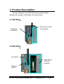
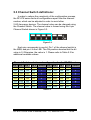
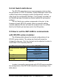
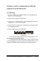
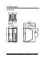
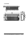
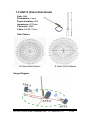
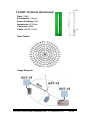
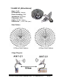
RF-87K1/2/5/9
User’s Manual
Warranty
All products manufactured by ICP DAS are warranted
against defective materials for a period of one year from the date of
delivery to the original purchaser.
Warning
ICP DAS assumes no liability for damages consequent to
the use of this product. ICP DAS reserves the right to change this
manual at any time without notice. The information furnished by
ICP DAS is believed to be accurate and reliable. However, no
responsibility is assumed by ICP DAS for its use, or for any
infringements of patents or other rights of third parties resulting
from its use.
Copyright
Copyright 2004 by ICP DAS. All rights are reserved.
Trademark
The names used for identification only may be registered
trademarks of their respective companies.
RF-87K1/2/5/9 User’s Manual, Rev: 1.0, 8MH-003-10
1/26
Table of contents
1.
Introduction........................................................................................3
2.
3.
Specifications ....................................................................................4
Product Description ...........................................................................5
3.1 RF-87K1..........................................................................................5
3.2 RF-87K2..........................................................................................5
3.3 RF-87K5..........................................................................................6
3.4 RF-87K9..........................................................................................6
4.
3.5 Block diagram .................................................................................7
Application .........................................................................................8
4.1 PC to RF-87K series: ......................................................................8
4.2 7188 series embedded controller to RF-87K series: .......................8
5.
4.3 8000 series embedded controller to RF-87K series: .......................9
4.4 RF-87K series network:...................................................................9
Setting the RF-87K series................................................................10
5.1 The switch’s descriptions of RF-87K series:..................................10
5.2 Init switches’ descriptions:............................................................. 11
5.3 Channel Switch definitions: ...........................................................12
5.4 Init Switch definitions:....................................................................13
5.5 How to set the SST-2450 to communicate with RF-87K series:....13
5.6 How to set the I-87K I/O module’s configuration at the RF-87K
series ...........................................................................................14
5.6.1 RF-87K1..............................................................................14
6.
5.6.2 RF-87k2/5/9 ........................................................................15
Dimension........................................................................................16
6.1 RF-87K1........................................................................................16
6.2 RF-87K2........................................................................................17
6.2 RF-87K5........................................................................................18
7.
6.4 RF-87K9........................................................................................19
Accessory ........................................................................................20
7.1 ANT-3 (Directional)........................................................................20
7.2 ANT-8 (Omni directional) ...............................................................21
7.3 ANT-12P (Directional)....................................................................22
7.4 ANT-15 (Omni directional) .............................................................23
7.5 ANT-18 (Directional) ......................................................................24
7.6 ANT-21 (Directional) ......................................................................25
7.7 ANT-15YG (Directional).................................................................26
RF-87K1/2/5/9 User’s Manual, Rev: 1.0, 8MH-003-10
2/26
1. Introduction
In order to reduce wire-placement tasks and conveniently
manage data acquisition modules, ICPDAS provide a range of RF
I/O modules to meet the above requirements.
The hardware structure is based on the ICPDAS I-87K series
module and the software supports the ICPDAS DCON protocol,
making it easy to integrate into any system.
There are three RF I/O series modules available for selection:
RF-87K1, RF-87K2, RF-87K5 and RF-87K9. The last character of
the model number denotes the number of slots.
The unique specifications of the RF I/O series modules means
that it supports the ICPDAS I-87K series I/O modules, meaning that
the old I-87K back end need only be changed to an RF I/O module
and the system can be updated to a wireless network.
The RF-87K series is based on a direct sequence spread
spectrum and RF technology, operating in the ISM bands with a
Frequency Range of 2410.496MHz~2471.936MHz, with a Channel
Spacing of 4.096MHz.
By changing the default antenna to a high gain antenna, the
transmission range of the RF-87K series can be extended. In
addition, the unique specifications of the RF-87K series allows the
channel to be changed using a simple switch, meaning that most
configuration problems can be easily solved when adding a new
module. It is also easy to add an RF-87K series module to your
existing SST-2400/2450 network.
Note that when ordering an RF-87K series module, I/O
modules are not included and must be purchased separately. The
RF-87K series also needs to operate with any device that is
connected to the SST-2450.
RF-87K1/2/5/9 User’s Manual, Rev: 1.0, 8MH-003-10
3/26
2. Specifications
Frequency Range:
Channel Spacing:
Output Power:
Transmission Power:
2.4GHz (2410.496MHz ~ 2471.936MHz)
4.096MHz
0.05W
17dBm 土 2dBm
I/O types and number:
Modulation technique:
Radio technique:
Depends on the chosen I-87K I/O module
GMSK
Direct sequence spread spectrum
Number of channels:
PN code rate:
Communication distance:
16
1.365 Mchips/sec.
Depends on the type of external antenna,
default is 300m
Setting Method:
Switching
Antenna:
Data Format:
Data bit error rate Antenna:
Input voltage:
Flexible
N, 8,1
< 1/1000@ -102dBm
10~30V DC
Input current:
Power Consumption:
Typically less then 250mA
Transmit: 2W
Receive: 1W
Dimensions:
106mm (L) x 76mm (W) x 31mm (H)
Weight:
Operating temperature:
Operating humidity:
200g
-10oC~50oC
0~90%
The RF I/O module can work together with an SST-2450 or SST-2400
network (the 8051 chip of the SST-2400 must be changed).
RF-87K1/2/5/9 User’s Manual, Rev: 1.0, 8MH-003-10
4/26
3. Product Description
The last character of the RF-87K series model number
identifies the number of available I/O module slots.
3.1 RF-87K1
Channel &
Init Switch
One slot for I-87K
I/O modules
3.2 RF-87K2
Init Switch
Two slots for
I-87K I/O
modules
Channel
Switch
RF-87K1/2/5/9 User’s Manual, Rev: 1.0, 8MH-003-10
5/26
3.3 RF-87K5
Five slots for I-87K
I/O modules
Init Switch
Channel
Switch
3.4 RF-87K9
Nine slots for I-87K
I/O modules
Channel
Switch
Init Switch
RF-87K1/2/5/9 User’s Manual, Rev: 1.0, 8MH-003-10
6/26
3.5 Block diagram
Transceiver
RF-87K series modules contain two elements. The first is the
RF module (for radio communication) and the second is the I-87K
module slot (for data acquisition).
When the Transceiver receives a signal from the RF module, it
will forward the signal to the RS-485 bus. On the other hand, if the
Transceiver receives a signal from the RS-485 bus it will forward
the signal to the RF module.
The RF-87K series wave signals cannot pass through metallic
obstacles, so this product is not suitable for a metallic type
environment.
The signal is able to pass thorough a cement wall, but will be
weakened to 50% of its efficiency for each 15cm of the wall
thickness.
RF-87K1/2/5/9 User’s Manual, Rev: 1.0, 8MH-003-10
7/26
4. Application
4.1 PC to RF-87K series:
4.2 I-7188 series embedded controller to RF-87K
series:
RF-87K1/2/5/9 User’s Manual, Rev: 1.0, 8MH-003-10
8/26
4.3 I-8000 series embedded controller to RF-87K
series:
4.4 RF-87K series network:
RF-87K1/2/5/9 User’s Manual, Rev: 1.0, 8MH-003-10
9/26
5. Setting the RF-87K series
5.1 Descriptions of the RF-87K series switches:
The definition is shown as below:
Channel Setting
I/O Module Init
RF-Init
Channel Setting: The first four bits allow the user to select any of
the sixteen channels. Refer to Table 5.3 in Section 5.3 for the
relevant settings.
I/O Module Init: The fifth bit switch is only valid for the RF-87K1
module. When the position of this switch is adjusted to ON, the
configuration of the I/O module that is connected to the RF-87k1
will be reset to the default settings (i.e. address = 01, Baud Rate =
115200bps).
RF-Init: The sixth bit is only used to set the configuration of the
I-87K I/O modules. When the position of this switch is adjusted to
ON, the Baud Rate of the RF-87K series will be changed from
9600bps to 115200bps.
RF-87K1/2/5/9 User’s Manual, Rev: 1.0, 8MH-003-10
10/26
5.2 Init Switch descriptions:
The RF-87K2/5/9 has an extra Init switch to set the channel
and Init status. The positions and the definitions are shown as
below:
RF-87K2
RF-87K5
RF-87K9
Init switch (the switch number
corresponds to the slot number)
RF-87K1/2/5/9 User’s Manual, Rev: 1.0, 8MH-003-10
11/26
5.3 Channel Switch definitions:
In order to reduce the complexity of the configuration process,
the RF-87K series limits all configurations apart from the channel
number, which can be adjusted in order to avoid other
2.4G-frequency devices. The channel value can be changed using
the Channel Switch. The channel value is formed using the 4-pin
Channel Switch shown in Figure 5.3.
Figure 5.3.
Each pin corresponds to one bit. Pin 1 of the channel switch is
the MSB, and pin 4 is the LSB. The ON position denotes that the bit
value is 0. Otherwise, the value is 1. Please refer to Table 5.3 for
additional available values.
Channel Switch and channel configuration for the RF-87K series
Pin 1 Pin 2 Pin 3 Pin 4 Channel Pin 1 Pin 2 Pin 3 Pin 4 Channel
ON ON ON ON
OFF ON ON ON
0
8
ON ON ON OFF
OFF ON ON OFF
1
9
ON ON OFF ON
OFF ON OFF ON
2
A
ON ON OFF OFF
OFF ON OFF OFF
3
B
ON OFF ON ON
OFF OFF ON ON
4
C
ON OFF ON OFF
OFF OFF ON OFF
5
D
ON OFF OFF ON
OFF OFF OFF ON
6
E
ON OFF OFF OFF
OFF OFF OFF OFF
7
F
Table 5.3.
RF-87K1/2/5/9 User’s Manual, Rev: 1.0, 8MH-003-10
12/26
5.4 Init Switch definitions:
The RF-87K series has one or more expansion slots to allow
the connection of I-87K I/O modules. System Managers often have
a difficult task when managing module configurations, and can
often forget the configuration settings, if not properly recorded. An
Init Switch has been included as a useful method for solving this
problem.
The Init Switch pin number corresponds to the slot. In the
firmware of each I-87K I/O module, there is a specific setting
(module address 00) that will reset the module once it is notified
that the Init Switch pin has been set to the ON position.
5.5 How to set the SST-2450 to communicate
with RF-87K series modules:
The following table shows the internal configurations of an
RF-87K series module. The values are fixed and cannot be
changed by the user. Only the channel can be adjusted in order to
avoid other 2.4G-frequency devices.
The internal configurations of the RF-87K series
Communication interface
RS-485
Mode
Half-Duplex
Slave
Synchronous
Baud Rate
9600 bps
Data Format
N, 8, 1
P/N code
F
Table 5.5.
In order to correctly communicate with RF-87K series modules,
the configuration of the SST-2450 should be set according to the
table above.
RF-87K1/2/5/9 User’s Manual, Rev: 1.0, 8MH-003-10
13/26
5.6 How to set the configuration of I-87K I/O
modules in the RF-87K series
5.6.1 RF-87K1
♦ Set pins 5 and 6 of the Channel Switch to the ON position as
shown in the following figure.
♦ Power-off then power-on the RF-87K1.
♦ Launch the *(1)(2) DCON Utility or terminal application to set the
configuration of the I-87K I/O module.
♦ After setting the configuration, remember to return pins 5 and 6
to the opposite position.
♦ Power-off then power-on the RF-87K1.
Figure 5.6.1.
*(1) The DCON Utility can be found on the attached CD. The
path is Napdos\Driver\DCON_Utility.
*(2) No matter what Baud Rate value is read via DCON Utility
or terminal application, please ensure that the Baud Rate value is
changed to 9600bps before completing the setting procedure.
RF-87K1/2/5/9 User’s Manual, Rev: 1.0, 8MH-003-10
14/26
5.6.2 RF-87K2/5/9
♦ Set pin 6 of the Channel Switch to the ON position as shown in
figure 5.6.2-1
♦ Set the Init Switch pin corresponding to the required slot to the
ON position. For instance, to adjust the configuration for the
second slot of the I-87K I/O module, set pin 2 of the Init Switch to
the ON position (refer to figure 5.6.2-2).
♦ Power-off then power-on the RF-87K2/5/9.
♦ Launch the *(1)(2) DCON Utility or terminal application to set the
configuration of the I-87K I/O module.
♦ After setting the configuration, remember to return pin 6 of the
Channel Switch, and pin 5 of the Init Switch to the opposite
position.
♦ Power-off then power-on the RF-87K1.
Figure 5.6.2-1.
Figure 5.6.2-2.
*(1) The DCON Utility can be found on the attached CD. The
path is Napdos\Driver\DCON_Utility.
*(2) No matter what Baud Rate value is read via DCON Utility
or terminal application, please ensure that the Baud Rate value is
changed to 9600bps before completing the setting procedure.
RF-87K1/2/5/9 User’s Manual, Rev: 1.0, 8MH-003-10
15/26
6. Dimensions
6.1 RF-87K1
RF-87K1/2/5/9 User’s Manual, Rev: 1.0, 8MH-003-10
16/26
6.2 RF-87K2
RF-87K1/2/5/9 User’s Manual, Rev: 1.0, 8MH-003-10
17/26
6.2 RF-87K5
RF-87K1/2/5/9 User’s Manual, Rev: 1.0, 8MH-003-10
18/26
6.4 RF-87K9
RF-87K1/2/5/9 User’s Manual, Rev: 1.0, 8MH-003-10
19/26
7. Accessories
Using an external antenna in conjunction with the SST-2450
allows the device to be used outdoors. The antenna is even water
resistant. Simply replace the default antenna with an external antenna
to allow data to be transmitted across distances of up to 1KM.
7.1 ANT-3 (Directional)
Gain: 3dBi
Polarization: circular
Power handling: 5W
Impedance: 50 Ohms
Connector: SMA
Cable: RG-58, 100cm
Dimension: 65mm x 65mm
Gain Pattern
Usage Diagram
RF-87K1/2/5/9 User’s Manual, Rev: 1.0, 8MH-003-10
20/26
7.2 ANT-8 (Omni directional)
Gain: 8dBi
Polarization: Linear
Power handling: 10W
Impedance: 50 Ohms
Connector: SMA
Cable: RG-58, 100cm
Gain Pattern
H-Plane Field Patterns
E-Plane Field Patterns
Usage Diagram
RF-87K1/2/5/9 User’s Manual, Rev: 1.0, 8MH-003-10
21/26
7.3 ANT-12P (Directional)
Gain: 12dBi
Polarization: Linear
Power handling: 10W
Impedance: 50 Ohms
Connector: SMA
Cable: RG-58, 100cm
Gain Pattern
H-Plane Field Patterns
E-Plane Field Patterns
Usage Diagram
RF-87K1/2/5/9 User’s Manual, Rev: 1.0, 8MH-003-10
22/26
7.4 ANT-15 (Omni directional)
Gain: 15dBi
Polarization: Vertical
Power handling: 10W
Impedance: 50 Ohms
Connector: SMA
Cable: RG-58, 100cm
Gain Pattern
Usage Diagram
RF-87K1/2/5/9 User’s Manual, Rev: 1.0, 8MH-003-10
23/26
7.5 ANT-18 (Directional)
Gain: 18dBi
Polarization: Vertical
Power handling: 10W
Impedance: 50 Ohms
Connector: SMA
Cable: RG-58, 100cm
Dimension: 263 L x 263 W x 30H (mm)
Gain Pattern
E-Plane Field Patterns
H-Plane Field Patterns
Usage Diagram
RF-87K1/2/5/9 User’s Manual, Rev: 1.0, 8MH-003-10
24/26
7.6 ANT-21 (Directional)
Gain: 21dBi
Polarization: Vertical
Power handling: 10W
Impedance: 50 Ohms
Connector: SMA
Cable: RG-58, 100cm
Dimension: φ610 x150 (mm)
Gain Pattern
E-Plane Field Patterns
H-Plane Field Patterns
Usage Diagram
RF-87K1/2/5/9 User’s Manual, Rev: 1.0, 8MH-003-10
25/26
7.7 ANT-15YG (Directional)
Gain: 15dBi
Polarization: Vertical
Power handling: 10W
Impedance: 50 Ohms
Connector: SMA
Cable: RG-58, 100cm
Gain Pattern
E-Plane Field Patterns
H-Plane Field Patterns
Usage Diagram
RF-87K1/2/5/9 User’s Manual, Rev: 1.0, 8MH-003-10
26/26