1
MA1057 OPC Server User Manual
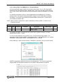
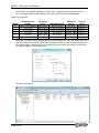
4.5.3 Creating Tags for the MAQ20-VO or -IO Output Module
On the demonstration system, MAQ20-VO module Ch 0 provides a -10V to +10V output signal
which drives the yellow LED bar display, labeled VOUT1, from zero to full scale, and Ch 4 drives
the TC Heat 1 control which simulates an elevated temperature measured by MAQ20-JTC module
Ch 6.
To determine the address to write to, use the Address Map for the MAQ20-VO or -IO Output
Modules found in the appendix of MA1042 MAQ20 Voltage & Current Output Module Hardware
User Manual. An excerpt from the MAQ20-VO Address Map is shown below. Channel Data is
stored starting at address 1000.
NOTE: When a module is registered in a system, addresses are offset by 2000 * R, where R is the
Registration Number.
Address Range 1000 - 1699 : Module Data
Start
Address
R/W
Number of
Registers
1000
R/W
8
Contents
Channel Data
Description
Data Range
Data
type
Data for each of 8 channels
Default = 2048
See Table
INT16
The MAQ20-VO module in the demonstration system has a registration number of 3 and an
address offset of 2000 * 3 = 6000.
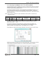
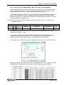
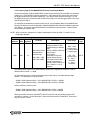
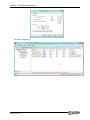
To write to Holding Registers using the OPC server, use base address range 400000. The
addresses to write to are then 400000 + 6000 (address offset) + 1000 (MAQ20-VO Ch 0) = 407000
and 400000 + 6000 (address offset) + 1004 (MAQ20-VO Ch 4) = 407004.
Choose Data type = Short and Client access = Read/Write. Scan rate is only for non-OPC clients.
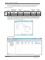
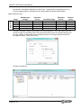
MAQ®20 output module ranges can be set on a per-channel basis. This can be set or checked
using the MAQ®20 Configuration Software Tool or ReDAQ® Shape Software for MAQ®20.
Page 21 of 32