1
56
107
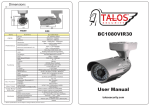
Dimensions
DIMENSION
144
FRONT
Items
TOP
Submenu
DV1080VIR24
Device
CMOS
1/3” 2MEGA CMOS
1944 (H) x 1092(V)
Effective
Resolution
Performance
Scanning system
Digital : 1080P(30p) , 720P(60P)
Max : 1,100TV lines(1080P)
Progressive
Color : 0.1Lux(50IRE)
Minimum illumination(F1.2)
S/N Ratio
OSD
Day&Night
B/W : 0.08Lux(50IRE)
More than 50dB (AGC off)
English/Japanese/German/Italian
Russian/Spanish/Chinese/Portuguese
Auto/Day/B&W/EXT1/EXT2
1800 ~ 10500K
ATW
High Speed Shutter
1/30(1/25) ~ 1/60Ksec
2~4
WDR
Off/ON
D-WDR
Functions
BLC
Off/ON (Size, Position)
HLC
Level Setting(0~20), Color
AGC
Level Setting(0~10)
D-Zoom
Camera ID
White Balance
DNR
0~96 Steps
Off/On (Letters A to Z, Numerals 0 to 9, Symbols)
AUTO / AUTOext / PUSH / MANUAL
3DNR, OFF/LOW/MIDDLE/HIGH
Motion Detection
Privacy Mask
Off/ON
32 Areas (On/Off, Color, Position)
Sens-Up
x2 ~ x4
Etc. Function
Sharpness, Reverse(H,V)
Etc. Function
Video Output
Visible Range
(LED On)
ColorBar
Off/ON
In/Output
Alarm Output
ANALOGUE
Video Output
Built-In 24 IR Leds(20M of Viewing Distance)
Outdoor
Built-In 24 IR Leds(10M of Viewing Diatance)
Lens
Power Consumption
Hardware
NTSC, PAL CVBS(without WDR)
Indoor
HD-SDI(SMA CONNECTOR)
Operating Temperature
Operating Humidity
Dimension
DV1080VIR24
2010 (H) x 1108(V)
Total
2.8~12mm DC Auto IRIS VF Lens
User Manual
DC 12V/ 24 AC, Less than 2.2Watts
Absolute : - 10C ~ +50C
Less than 90%
144mm (W) x 107mm (H) x 144mm(W)
Weight
*** Above specifications can be subject to change without previous notice***
920g
talossecurity.com
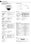
INSTALLATION
1
Mount Base
Mount Base
2
3
4
“L” Wrench
Wrench Screw
Mount Base
Camera
Insert
Open
Cover
Ring
Lock
Fixing Screw
Fix the mount base onto the ceiling
or wall by the fixing screw and insert
the camera like the arrow direction.
Camera Body
After insert the camera body to the mount base
like the Fig1 and slide the camera body just like
the Fig2 to fix the camera onto the base.
6
5
Camera
Gimbal
Gimbal Cap
Camera Body
Fix the screw into screw hole in the mountbase by using the “L”wrench and tighten
the camera body onto the base.
7
“L” Wrench
Unscrew the cover ring screw by
using the “L”wrench and open
the cover ring.
8
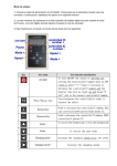
OSD
Controller
Video
test Port
Safety
Cable
Cover
Ring
“L” Wrench
Open the bubble cap and move the camera gimbal
to left, right and up, down to set the viewing direction.
After set the viewing direction, open the gimbal cap
like the arrow diection snd adjust the viewing angle.
Set the desired OSD feature by using the OSD controller.
(Refer the SOD manual to set up the desired OSD)
in case of a installer has portable monitor, connect the
video jack to the video test port to set up the OSD.
Close the dome cover just like above
Fig7 to tighten the screw.
Tighten the screw by using the “L”wrench
and complete the installation.