1
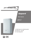
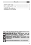
Model sam-12
Ultrasonic
Diathermy
Device
Directions
for Use
Contents
1.Introduction ............................................................................................................................................... 4
2. Indications for Use ................................................................................................................................. 4
3.Safety ........................................................................................................................................................... 5
3.1.Contraindications .................................................................................................................................... 5
3.2.Warnings ..................................................................................................................................................... 5
3.3.Precautions ................................................................................................................................................ 6
4. Features of the sam Device ............................................................................................................. 8
5. sam Components ............................................................................................................................... 9
6. Operator Interface ................................................................................................................................ 10
7.Accessories ............................................................................................................................................. 10
8. LED Display ............................................................................................................................................... 11
9. Initial Setup Instructions .................................................................................................................... 13
10. Treatment Options ................................................................................................................................ 13
sam
11. Application Instructions ..................................................................................................................... 16
12. Device Power Down and Removal ................................................................................................ 22
13. Modes of Operation ............................................................................................................................ 23
14. Cleaning and Maintenance .............................................................................................................. 24
15. Storage and Operating Conditions .............................................................................................. 24
16. Disposal of Waste Products ............................................................................................................ 25
17.Appendix .................................................................................................................................................. 26
A. Symbols ......................................................................................................................................... 26
B. Specifications .............................................................................................................................. 27
C.Notice of Compliance, Calibration and Operational Period .................................... 28
D. Technical Information .............................................................................................................. 29
E. Electrical Immunity and Emissions .................................................................................... 30
F. Warranty ......................................................................................................................................... 33
G. Troubleshooting ........................................................................................................................ 34
Product Support 203-349-2798
ZetrOZ, Inc.
3
Product Support 203-349-2798
1. Introduction
3. Safety
Thank you for choosing the sam Ultrasonic Diathermy Device! This manual contains
general instructions for operation, application, precautions, and maintenance. In order
to obtain maximum life and efficiency from the sam Device and to assist in the proper
operation of the device, please read and understand this manual thoroughly. This
device is only to be used as directed in this manual.
3.1. Contraindications
sam was developed as a next generation wearable ultrasound therapy system which
• Over the eyes
• Over or near growth centers until bone growth is complete
• Over the reproductive organs
• Over the pregnant uterus
• Over a healing bone fracture
• On the thoracic area if the patient is using a cardiac pacemaker
• Over an active implanted medical device such as an implanted deep brain
stimulation device
• On the brain, spinal cord, or large subcutaneous peripheral nerves
• Ischemic tissues in individuals with vascular disease where the blood supply
would be unable to follow the increase in metabolic demand and tissue necrosis
might result
combines miniaturization technology into a small and portable ultrasound therapy
system. It is designed to work with the human body and maximize the safe and effective
delivery of long-duration therapeutic ultrasound. Simple to administer and operate on a
broad range of body types, sam allows the delivery of ultrasound treatment for up to
four hours. It operates at a preset frequency and allows the use of up to two applicators
simultaneously. Applicators are applied and secured to the surface of the body using
convenient sam Ultrasound Coupling Bandages.
The specifications put forth in this manual were in effect at the time of publication.
1.1. General Safety
Thoroughly read and understand the precautionary and operating instructions before
attempting to operate the sam Ultrasonic Diathermy Device. Know the limitations and
hazards associated with using any ultrasound device. Observe the precautionary and
operational decals placed on the device. Periodically review the operation procedures
and safety precautions outlined in this manual.
1.2. Prescription Use Only
Caution: Federal law restricts this device to sale by or on the order of a practitioner
licensed by the law of the state in which he/she practices to use or order the
use of the device.
Contraindications for the use of ultrasound include:
• Over an area of the body where a malignancy is known to be present
3.2. Warnings
This device complies with 21 C.F.R. § 1050.10
2. Indications for Use
The sam Ultrasonic Diathermy Device is intended to apply ultrasonic energy to
generate deep heat within body tissues for the treatment of selected medical
conditions such as the relief of pain, the relief of muscle spasms, the treatment of joint
contractures and the local increase of circulation.
Product Support 203-349-2798
• Instruct the patient to inform the practitioner if the patient feels any pain or
burning during treatment.
• Instruct the patient how to turn off the sam Device and remove the sam
Applicator if the patient feels any pain or burning during treatment.
• If the Lock Switch is in the locked position it must be placed in the unlocked
position to disable the power. Locking the treatment settings is optional and not
required for treatment.
• ALWAYS administer treatment using a new sam Ultrasound Coupling Bandage.
Use one sam Ultrasound Coupling Bandage per applicator. Use of the sam
Ultrasound Applicator without a new sam Ultrasound Coupling Bandage MAY
RESULT IN BURN and/or REPEATED SHUTOFF of the sam Applicator.
• The sam Device should be kept out of the reach of children.
The sam Ultrasonic Diathermy Device is a prescription use device. sam should only
be administered and monitored by a licensed healthcare practitioner.
4
• If the treatment is reported as painful or too hot at any point during treatment,
turn off device and remove the device from the skin.
ZetrOZ, Inc.
5
Product Support 203-349-2798
• DO NOT apply the sam Applicator with alternative coupling media as a
replacement for the sam Ultrasound Coupling Bandage. Use of alternative
coupling media in lieu of the sam Ultrasound Coupling Bandages may reduce
the effectiveness of treatment, lead to automatic shutoff of the applicator, or
cause a burn.
• DO NOT administer treatment if the applicator is not connected to a sam
Ultrasound Coupling Bandage.
• Applicators and sam Ultrasound Coupling Bandages are not sterile. DO NOT
apply this device over an open wound or inflamed skin.
WARNINGS
• This device is rated IPX-0; therefore, it is Not Waterproof. DO NOT apply a direct
stream of any liquid onto the device, submerge the device, or allow any liquid to
pool on the surface of the device. DO NOT use if device has been submerged
in water.
• This device contains a rechargeable lithium-ion battery. DO NOT disassemble,
DO NOT heat above 100°C, DO NOT incinerate or expose to water and
DO NOT ingest.
• DO NOT use if the sam Ultrasound Coupling Bandage if the sam Ultrasound
Media is dried out. Indications of a dried out bandage include: the cup is not
full of gel, there is dry residue or film in the cup, or there is any cut, break, or
opening in the bandage or seals.
• The use of accessories, transducers and/or cables other than those specified,
with the exception of those sold by the manufacturer as replacement parts for
internal components, may result in increased emissions or decreased electrical
immunity of the equipment or system.
• DO NOT apply directly over a bone that is near the skin surface.
• DO NOT open or modify any component of the sam Device. Hazards such
as shock, burn or inappropriate functionality can result from unauthorized
modification of the sam Device.
• Use of the sam Device around electromagnetic interference may negatively
affect the output performance and safety of the device. Do not use the device if
any abnormal functionality occurs.
3.3. Precautions
Precaution should be taken when using the device:
3.5. Electronics and Battery
• Over an area of the spinal cord following a laminectomy, i.e. when major covering
tissues have been removed
PRECAUTIONS
• Only recharge the sam Device using the sam Electrical Charger. Use with any
other recharging device may result in damage to the system and void
all warranties.
• On patients with hemorrhagic diatheses
• Over areas where metal prosthesis or other metallic implants are embedded
in tissue which may form a reflective surface to the ultrasound energy causing
unintended irradiation of tissue and excessive heating
• When not in use, power ‘OFF’ the device to protect the functionality of
the components.
• Over an acute infection or sepsis
• On patients with peripheral artery disease
• Avoid dropping the applicator or power controller and avoid scratching the
lens of the applicator. Rough handling may reduce the device’s acoustic output
power, thereby reducing the effectiveness of therapy.
• Over a deep vein thrombosis
• Over an anesthetized area or in conjunction with a condition that causes
impairment of sensation, such as caused by chemotherapy
• The power controller and applicators should be routinely checked for cracks and
other damage before each use to determine that the device functions normally.
• When using the sam Ultrasound Coupling Bandage, ensure the top and bottom
seals have been completely removed before attaching the applicator to the skin
• DO NOT place the device in a location where the power charging cord could be
a trip hazard.
• DO NOT use sharp objects such as a pencil point or ball point pen to operate the
buttons on the control panel as damage may result.
• Prevent potential electromagnetic or other interference. DO NOT open the sam
Device or connect the device or components of the device to any non-sam
part. Keep the device clean and make sure no exposed non-insulated wires are
visible. If damage is present, do not administer treatment.
3.4. Inflammable gases and anesthetics
• Warning: Explosion hazard if used in the presence of flammable anesthetics,
open flame, or oxygen-rich environment
6
Product Support 203-349-2798
ZetrOZ, Inc.
7
Product Support 203-349-2798
4. Features of the sam Device
5. sam Components
UB-12
4.1. Preset Treatment
UB-12
PMC-12
10
The sam Device is preconfigured to provide continuous ultrasonic output at a preset
frequency and intensity which cannot be modified by the user. The user can set the
treatment duration to be 1, 2, 3, or 4 hours.
%
HRS
0
4
80
3
2.5
60
2
1.5
40
4.2. sam ULTRASOUND APPLICATORS
3.5
AT-12
1
20
DONE
The sam Ultrasound Applicators serve as the ultrasound transducers of the
sam Device. The applicators offer low-profile design with light emitting diode (LED) on/
off notification. The ergonomic plastic housing and smooth contours provide
enhanced comfort.
YB-12
YB-12
CT-12
4.3. sam SENSING
if included
sam is designed to work with the human body and maximize the safe and effective
delivery of long-duration therapeutic ultrasound. Each sam Applicator is equipped
AT-12
with closed-loop continuous temperature monitoring which maintains treatment site
temperatures below 44°C during normal operation. See section 13.4 on page 24 for
more information.
AT-12
AT-12
AT-12
4.4. sam ULTRASOUND COUPLING BANDAGES
The sam Device utilizes ultrasound coupling bandages which are manufactured with
ultrasound coupling media sealed inside. The ultrasound coupling bandages ARE
REQUIRED to secure the sam Applicators to the body.
4.5. Battery Operation
Powered by a rechargeable lithium-ion battery, the sam Device can provide
4 hours of therapy on a single battery charge.
4.6. Lock Switch
The sam Power Controller Module includes a slide lock switch that allows the locking
of treatment settings so that they cannot be inadvertently modified during a 1 – 4 hour
treatment session. Locking the sam Power Controller Module will disable both the
treatment time toggle button and the power ON/OFF button. To disable the device or
modify treatment time once in locked mode, the lock switch must be moved to the
unlocked position. Similarly, the device cannot be turned on while in locked mode and
must be unlocked first. The use of the locking feature is OPTIONAL.
8
Product Support 203-349-2798
YB-12
figure 1: sam Model-12 Components
YB-12
sam MODEL 12 COMPONENTS
AT-12: Ultrasound Applicators
UB-12: Ultrasound Coupling Bandages
OM-12: User Manual
PMC-12: Power Controller Module
CT-12: Electrical Charger
YB-12: Y-branch Adapter
ZetrOZ, Inc.
9
Product Support 203-349-2798
6. Operator Interface
8. LED Display
The sam Device contains Light Emitting Diode (LED) displays that indicate the
functions of the device (see Figure 2).
Treatment
Battery
Power Button Timer LED Indicator LED
Indicator LED
HRS
0
10
%
8.1. Power Controller Indicator LED
The Indicator LED provides power, charging and error checking information.
Toggle
Button
4
80
60
3.5
33
2.5
2.5
3.5
2
1.5
40
1
20
DONE
Lock Switch
Indicator LED
Front
Side
Charge Port
Applicator
Connection
Bottom
Color of Indicator LEDMeaning
Opaque (absence of light) Power Controller is OFF.
No power is being generated
Blue Power Controller is ON. Note – Ultrasonic
energy is generated only when the Power
Controller is connected to the sam
Applicator(s)
Green
Power Controller battery is fully charged
Amber
Power Controller battery is charging
RedToo many applicators are attached. A
maximum of two applicators may be
attached to a single power controller at
any time
Table 1. Power Controller LED Color Definitions
figure 2: sam Interface Components
7. Accessories
The sam Device may be used with any of the following accessories:
sam Belt Clip
sam Armband
sam Carrying Case
* Additional sam Ultrasound Coupling Bandages may be obtained by contacting
the manufacturer
10
Product Support 203-349-2798
ZetrOZ, Inc.
11
Product Support 203-349-2798
8.2. Control Panel
The front face of the sam Power Controller Module contains a control panel. The
LEDs on the control panel are divided into a field for Battery Indicator and a field for
Treatment Timer. The operator is able to make selections by pressing the Power Button
and the Toggle Button.
Color of Battery Indicator LED*Meaning
Red Only
Low Battery, Re-Charge required
Blinking Red
Re-Charge required
Amber
Power Controller is partially charged
Green
Power Controller fully charged
*These lights remain on for 4 seconds and subsequently turn off
Table 2. Battery Indicator LED Color Definitions
9. Initial Setup Instructions
Remove the sam Device components (Figure
1) from the packaging and inspect for any damage
that may have occurred during shipment. Charge
the device for up to 6 hours or until the Power
Controller Indicator LED is Green. The sam Device
arrives only partially charged due to generally
accepted shipping practices.
9.1. Charging the Power
Controller Module
Treatment Time Indicator LEDMeaning
BlueTreatment time remaining. Treatment
timer is set in one hour increments and
will count down in 30 minute increments
AmberTreatment complete. This single “done”
light will activate only when a treatment
cycle has completed and will remain
illuminated for 8 hours, then turn off
Table 3. Treatment Time Indicator LED Color Definitions
Micro USB
Micro USB
Bottom of sam Power Controller
figure 3A
A. Plug the micro USB end of the sam
Electrical Charger into the charging port on
the bottom of the sam Power Controller.
Wall Charger
Bottom of sam Power Controller
Wall Charger
Outlet
B. Plug the electrical charger into a 120/230
VAC wall outlet. The sam Power Controller
Module indicator LED will be amber. When
the device is fully charged the top right
indicator LED will change from amber
to green.
10. Treatment Options
Outlet
figure 3B
10.1. Treatment Duration
8.3. Applicator Indicator LED
LED ColorMeaning
Opaque (absence of light)
Applicator is not receiving power
BlueApplicator is receiving power from the
Power Controller. Ultrasonic energy is
being generated at all times this light
is illuminated
Red (accompanied by vibration)sam Sensing Mode. No Ultrasonic energy
is being generated from this applicator
while this light is illuminated
Table 4. Applicator LED Color Definitions
12
Product Support 203-349-2798
The sam Ultrasonic Diathermy Device provides
ultrasound therapy at a preset frequency and
intensity. The user can program the treatment
duration to be 1, 2, 3, or 4 hours. The maximum
treatment duration setting on the sam Device
is 4 hours. Treatment duration should be set to
the minimum increment required for effective
therapy. Due to individual differences in skin type
and tolerance, it is recommended to begin with a
1 hour treatment. Increase treatment duration in
subsequent applications only as tolerated. Maximum
usage time is 4 hours per day per treatment area.
The sam Device may be used while charging.
Charging the device during treatment has no impact
on device frequency or intensity output settings. If
using sam while charging, position the device in
such a way that the charger cable is easily removed
from the power controller module if needed.
ZetrOZ, Inc.
13
Product Support 203-349-2798
10.2. Treatment Locations
10.3.2. Dual-Applicator Mode
Figures 4 and 5 depict examples of device
placement on two treatment locations. Figure
4A and 4B illustrates using the sam Device with
one applicator on the shoulder and knee. Figure
5A and 5B illustrates using the sam Device with
two applicators on the shoulder and knee. When
determining treatment location, consider that
the maximum diathermic effect will occur directly
under the applicator face; therefore, placing
the applicator near or directly over the target
area while following all warning and cautionary
instructions is advised.
The Y-adapter (optional) may be used to power two Applicators simultaneously. As
shown in Figure 8, connect the Y-adapter directly to the Power Controller wire and then
connect each Applicator to a wire jack at the other end of the Y-adapter.
Shoulder
When using two sam Applicators and two sam Ultrasound Coupling Bandages
simultaneously, the sam Ultrasound Coupling Bandages should be positioned so that
their footprints do not overlap.
figure 4A: Single Shoulder Application
Caution: DO NOT overlap sam Ultrasound Coupling Bandages (Figure 6).
Caution: DO NOT use the Y-adapter when using only one applicator for treatment.
Caution: Do NOT attach more than one Y-adapter to the sam Device.
Note: These figures are examples and are not
intended to be the suggested or only
allowable applicator configurations for those
body locations.
Note: If two applicators will be used, two sam Ultrasound Coupling Bandages (one for
each applicator) and the Y-adapter must be used for the treatment.
Warning: D
o Not apply directly over a bone that is
near the skin surface.
Knee
figure 4B: Single knee Application
10.3. One or Two Applicators:
The sam Device may be used with one or two
applicators simultaneously. The decision to use
one or two applicators is dependent on the
size and anatomical area of treatment. Using
two applicators allows a larger area of tissue to
receive ultrasound treatment. For example, large
anatomical regions, such as the shoulder could
benefit from two applicators, whereas smaller
treatment areas such as the forearm may only
require one.
figure 6: NO Bandage Overlap
figure 5A: Dual Shoulder Application
10.3.1. Single-Applicator Mode
Connect the power controller wire to a single
applicator by inserting the power controller wire
jack into the matching cavity at the base of the
applicator. The port for the power controller wire is
described as ‘Applicator connection’ on the Power
Controller drawing shown in Figure 2, page 10.
figure 5B: Dual Knee Application
14
Product Support 203-349-2798
ZetrOZ, Inc.
15
Product Support 203-349-2798
11. Application Instructions
A. To prevent accidental activation during
shipping, the device will arrive to the user
in the ‘locked’ position. To unlock the
device, slide the Lock Switch on the sam
Power Controller ‘up’ into the ‘unlocked’
position (Figure 7A).
B. Gently twist the wire jack clockwise until the applicator edge is flush with the
wire jack (Figure 8B).
Lock
Switch
45
2
2.5
3
1.5
3.5
4
1
45
figure 7A: Check Device Charge
DONE
0
10
20
40
i. To check the treatment duration for
which the battery charge is capable of
fulfilling, simply continue to press the
Toggle Button sequentially to view all
timer settings allowed by the current
battery charge. See section 9 for
charging instructions.
A. Insert the power controller wire into the matching cavity at the base of the
applicator at a 45 degree angle (Figure 8A).
HRS
B. Check to make sure the Power Controller
holds enough charge to provide the
desired duration of treatment. Press
the Toggle Button on the sam Power
Controller to view the battery indicator
lights (Figure 7B). The lights will illuminate
to show how much battery life is remaining
in the device. If the device is not fully
charged it may not be able to deliver
treatment for 4 hours. The device will only
permit the user to set a treatment duration
for which the battery charge is capable
of fulfilling.
%
Check Device Charge
80
* If using 2 applicators: first connect the Y-adapter directly to the power controller
wire jack and then connect each applicator to a wire jack at the other end of the
Y-adapter (Figure 8*).
60
11.1.
11.2. Connect Applicator to Power Controller
figure 8*: Connecting Y-Adapter
figure 8A: Insert power controller wire at 450 angle
Rotate Clockwise
Rotate Clockwise
Toggle
Button
figure 8B: Gently twist to Lock
figure 7B: Check Device Charge
16
Product Support 203-349-2798
ZetrOZ, Inc.
17
Product Support 203-349-2798
11.3. Attach Applicator to Bandage
11.4. Apply Ultrasound
Coupling Bandage to
Treatment Location
A. Remove the circular seal from the top of
the bandage to reveal the coupling media
within the gel cup (Figure 9A).
B. Attach the applicator, face down, into the
coupling media (Figure 9B).
C. Firmly press the applicator down onto the
center of the gel cup until a clicking noise
is heard or clicking sensation is felt
(Figure 9C).
A. Hold the applicator so the bottom of the
bandage faces up. Remove the paper liner
from the back of the bandage, revealing
the bandage adhesive (Figure 10A).
i. The circular seal should peel off the
bottom of the gel cup along with the
paper bandage liner. If it does not peel
with the paper, be sure to peel away
the circular seal so the coupling media
is completely uncovered.
ii. Add more sam Coupling Media
as needed.
figure 9A: Removing Foil Seal
If using dual applicators, repeat these steps with
the second applicator and the second bandage.
Note: When the applicator is pressed down onto
the gel cup, do not be concerned if coupling
media flows out the edges of the gel cup.
Wipe any excess coupling media away with
a tissue or towel.
Note: Ensure the applicator is fully attached to
the bandage.
B. Turn the bandage over and adhere the
bandage to the desired treatment location
(Figure 10B).
figure 9B: Attach Applicator
figure 10A: Removing Paper Liner
i. The sam Coupling Media must be in
direct contact with the skin.
If using dual applicators, repeat these steps to
adhere the second bandage and applicator to the
second treatment site.
Note: When applying bandages, both sides of
the ultrasound coupling media should be
uncovered. One side should be in contact
with the skin. The other side should be in
contact with the face of the applicator.
Knee
figure 10B: Adhere Bandage to Site
figure 9C: Press Applicator Down
18
Product Support 203-349-2798
ZetrOZ, Inc.
19
Product Support 203-349-2798
11.5. Turn the Device ‘ON’
11.6. Prevent Unintentional Shutoff
A. Check to make sure the Lock Switch is in
the ‘unlocked’ position (Figure 11A).
B. Press and hold the Power Button on
the sam Power Controller for at least 1
second to turn the device ‘ON’ (Figure 11B).
Toggle
Button
i. As confirmation that the device is ‘ON’,
the LEDs on the sam Power Controller
will illuminate blue (treatment timer and
indicator LEDs) and the indicator LED
on the applicator will illuminate blue.
ii. The battery indicator LEDs will remain
‘ON’ for about 4 seconds after turning
‘ON’ the device.
Lock
Switch
figure 11A: Slide to Unlocked Position
iii. The treatment timer LEDs and blue
indicator LEDs (power controller and
applicator) will remain ‘ON’ for the
duration of treatment.
Power Button
C. Press the Toggle Button to select 1, 2, 3 or
4 hour treatment duration (as allowed by
current battery charge) (Figure 11C).
i. If the Toggle Button is pressed up to
the 4 hour setting and a decreased
treatment time is desired, pressing it
again will return the treatment timer to
the 1 hour setting.
%
0
10
HRS
4
80
3.5
3
2.5
2.5
60
2
1.5
1.5
40
11
20
DONE
Once satisfied with the treatment settings, the
settings may be locked to prevent unintentional
shutoff during treatment by sliding the Lock Switch
down into the ‘locked’ position as indicated by
the symbols on the sam Power Controller (see
Figure 11A). In this state the settings cannot be
changed until the Lock Switch is moved back to the
‘unlocked’ position.
Note: The system is not required to be locked in
order to operate. Always be aware of how
to disable a locked device. Always notify the
patient if their device is locked.
11.7. Treatment Delivery
Treatment will be delivered for the duration set by
the user. The treatment timer LEDs will count down
in 30 minute increments as treatment progresses.
Upon completion, the device will automatically shut
off and the ‘treatment complete’ LED will illuminate
for approximately 8 hours before turning off. See
section 12 for how to manually power ‘OFF’
the device.
Warning: If the sam Lock Switch is in the locked position, the sam Power Button will
not turn off the device until the sam Lock Switch is placed into the
unlocked position.
figure 11B: Press Power Button
Toggle
Button
Warning: ALWAYS instruct the patient to alert the practitioner in the event of discomfort
during treatment.
Warning: As an additional safety measure, ALWAYS instruct the patient how to turn off
the sam Device and remove the sam Applicator in the event of discomfort
or emergency.
Warning: ALWAYS keep the sam Power Controller within easy reach so that power may
be ceased at any time.
Lock
Switch
figure 11C: Select Duration
20
Product Support 203-349-2798
ZetrOZ, Inc.
21
Product Support 203-349-2798
12. Device Power Down and Removal
13. Modes of Operation
12.1. P
ower OFF the Power Controller
13.1. ON (Unlocked) Mode
Move the Lock Switch up to the ‘unlocked position’ (if locked) then press and hold the
Power Button on the sam Power Controller for at least 1 second to turn the device
‘OFF’ (See Figure 11B for device diagram).
To turn the device ‘ON’, first ensure the Lock Switch is in the unlocked position as
indicated by the unlocked symbol on the sam Power Controller Module. Press and
hold the Power Button for at least 1 second. Press the Toggle Button on the right side
of the sam Power Controller Module to set the treatment duration. The treatment
duration may be set for 1, 2, 3 or 4 hours. The battery indicator LED and treatment timer
LED will be displayed on the control panel (see section 8: LED Display). The applicator
indicator LED will be displayed on each attached applicator (See Figure 2, page 10).
Each connected applicator will emit ultrasound energy immediately upon the sam
Power Controller Module entering the ‘ON’ mode of operation. The sam Applicator will
emit ultrasonic energy whether the device is locked or unlocked (locking is optional). A
powered sam Applicator will always emit ultrasonic energy unless it enters the sam
Sensing Mode or the treatment duration concludes.
12.2. Remove Device from Skin
A. Remove the bandage(s) from the skin.
B. Remove the applicator from the sam Ultrasound Coupling Bandage by pulling
the tab on the side of the gel cup. This unlocks the cup from the applicator
(See Figure 12).
C. T
hrow away the sam Bandages.
13.2. ON (Locked) Mode
Warning: N
EVER use a sam Ultrasound Coupling Bandage for more than one use.
Misuse of sam Ultrasound Coupling Bandages or use for more than the
intended treatment duration MAY RESULT IN BURN OR REPEATED SHUTOFF
of the applicator.
12.3. Clean the Applicators
Clean any residual ultrasound coupling media off of the applicator and off of the skin.
See section 14 for ‘Cleaning and Maintenance’ details.
12.4. Recharge the Device
Warning: If the Lock Switch is in the locked position, the Power Button will not turn off
the device until the Lock Switch is placed into the unlocked position. Locking
the treatment settings is not required.
13.3. Off Mode
When the device is ‘OFF’, the LEDs on the applicator will not be illuminated, the LEDs
on the sam Power Controller Module will not be illuminated, and no ultrasound energy
will emanate from the device. Always turn the device ‘OFF’ when not in use or if pain or
uncomfortable heating is indicated by the patient.
M
A O
T D
-1
2E
L
Connect the sam Power Controller to the sam Electrical Charger for recharging. Prior
to the next use, allow up to 6 hours to recharge the battery to 100% charge. See section
9 for charging instructions.
Once the device is powered ‘ON’, the user may lock the control panel settings by
sliding the Lock Switch on the sam Power Controller Module to the ‘locked position’ as
indicated by the lock symbol on the sam Power Controller Module. This will prevent the
device from unintentional shutoff during treatment. While locked, the Power Button and
the Toggle Button cannot be modified. The sam Applicator will emit ultrasound whether
the device is locked or unlocked. To change the treatment duration or turn the power
off, simply slide the Lock Switch to the ‘unlocked position’ as indicated by the symbols
on the sam Power Controller Module then press the desired user button.
Pull Tab
figure 12: Removing Applicator
22
Product Support 203-349-2798
ZetrOZ, Inc.
23
Product Support 203-349-2798
13.4. Sam Sensing Mode
In the event that the treatment site underneath the applicator reaches the temperature
threshold, the applicator will pause ultrasound output and vibrate once with a red LED
notification to signify that the device has begun a cooling or rest cycle. sam Applicator
will automatically resume treatment with a blue LED notification after the site
has cooled.
Warning: S
hould the patient ever report discomfort or a painful sensation from the site
under the sam Applicator, the applicator should be removed immediately.
Caution: At no time during treatment should the applicator be covered by thick
insulating material such as a coat, blanket or sports wrap. This may cause
sam to disable and remain disabled throughout the therapy session.
15. Storage & Operating Conditions
15.1. Storage
Store the sam Device in the following conditions:
Temperature: 5-57 °C;
Humidity: 10-80%;
Atmospheric pressure range: 700-1060 hPa
Store the sam Ultrasound Coupling Bandages in the following conditions:
Temperature: 5-30 °C;
13.5. End of Treatment Mode
At the end of treatment, an amber-colored “Treatment Complete” LED will illuminate on
the sam Power Controller Module and all other displays (battery indicator, treatment
timer, indicator LED, and applicator LEDs) will be inactive. All ultrasound emissions from
the applicator will cease. The “Treatment Complete” LED will remain illuminated for
approximately 8 hours after completion of therapy, at which point it will time out and
turn off. To set the sam Device for a new treatment, remember to move the lock switch
to the unlocked position and assess whether the sam Device requires recharging.
Humidity: 10-80%;
Atmospheric pressure range: 700-1060 hPa
15.2. Operation
Only operate the sam Device in the following conditions:
Temperature: 1-44 °C;
14. Cleaning and Maintenance
The exterior of the sam Power Controller and the applicator surfaces may be cleaned
with a soft cloth, tissue, or towel and one of the following cleaning agents: mild
detergent and water or disinfecting medical wipes.
Humidity: 10-80%;
Atmospheric pressure range: 700-1060 hPa
Caution: Do not keep the device in extreme hot or cold temperatures (above 50°C or
below 0°C). Do not leave the sam Device in a hot or freezing car. Do not leave
the device in direct sunlight for extended periods. UV light may damage or
discolor the device.
Caution: Properly clean the applicator between treatments.
Caution: The device is not waterproof. Do not apply a direct stream of liquid onto the
device, submerge the device, or allow any liquid to pool on the surface of
the device.
Caution: DO NOT USE: Phenolic-based disinfectants, quaternary ammonium, chlorinebased disinfectants, solvent-based cleaners, or abrasive materials. Doing so
may damage the plastic housing and void the warranty.
24
Product Support 203-349-2798
16. Disposal of Waste Products
sam Ultrasound Coupling Bandages are one time use and may be disposed of in
regular sanitation trash. No special disposal procedures are necessary.
Old, damaged or expired sam Power Controller Modules and applicators should be
recycled or returned to the manufacturer for proper disposal.
ZetrOZ, Inc.
25
Product Support 203-349-2798
17. Appendix
B. Specifications
The sam Device does not contain microprocessor or software
A. Symbols
0.65 W +20% per transducer
Power Output
1.3 W +20% for 2 transducers
Maximum Intensity
0.132 W/cm2 +20%
Frequency
3 MHz +20%
Consult User Manual/Instructions for Use
Manufacturer/Date of Manufacture
Duty Cycle
100% - continuous wave
Lithium-ion battery inside
Beam Form
Wide Beam – 5 degree diverging lens
Class BF Applied Part
Individual Transducer Dimension
5 cm2 emitting surface area (circular)
Do not use if package is damaged
Do not reuse
Non-ionizing radiation
Separate collection for electrical and electronic equipment. Must not
be disposed of in unsorted municipal waste.
Caution, consult accompanying documents
Input Voltage
100-240 V, 50-60 Hz
Diverging beam
Input Current
0.2 A
Continuous wave (CW)
Output Voltage
5 V DC
Output Current
1.2 A
Max Output Power
6W
Li-ion
W
Watts, ultrasonic power
MHz
Frequency in megahertz
ERA
Effective radiating area
BNR
Beam non uniformity ratio
Maximum Acoustic
BNR<5:1
ERA
6 cm2
Maximum Treatment Duration
4 hours
Other Electrical Ratings for the sam Device Components
Electrical Charger (Model GS2U-006-050-A)
Power Controller
Output Voltage
3.7 V DC +10%
Use by date
Max Output Amperes
700 mA
Temperature limits
Battery Protection
Max Current: 2 Amps
Max Voltage: 4.2 V
Humidity limitation
SN
LOT
Min Voltage: 3.1 V
Serial number
Cable Voltage Rating
300 V
Catalogue/Reorder Number
Cable 20°C Resistance:
94/km
Lot number
26
Product Support 203-349-2798
ZetrOZ, Inc.
27
Product Support 203-349-2798
D. Technical Information
Applicator
Input Voltage: 3.7 V DC +10%
Ultrasound Frequency: 3 MHz +20%
Ultrasonic Output Power:
1 Transducer: 0.65 W +20%
2 Transducers Together: 1.3 W +20%
Max Input Current: 400 mA
Y-Adapter
Voltage Rating
300 V
20°C Resistance 94/km
C. Notice of Compliance, Calibration and
Operational Period
The sam Device meets performance standards under 21 C.F.R. § 1050.10 PERFORMANCE STANDARDS FOR SONIC, INFRASONIC, AND ULTRASONIC RADIATIONEMITTING PRODUCTS. The sam Device meets IEC 60601-1, 3 ed. (2012); IEC 606011-2, 3 ed. (2007); Medical Electrical Equipment, General Requirements for Safety;
Electromagnetic Compatibility. The sam Device is calibrated to provide 3 MHz +20%
ultrasound diathermy at 0.65 W +20% per ultrasound applicator.
figure A. Ultrasound Field Scan Across Applicator Face
Operational Period:
The sam Power Controller Module is intended to maintain calibration for up to 300
charging cycles and each ultrasound applicator is intended to withstand 1500 hours
of run time, after which the system should be recycled or returned to ZetrOZ, Inc. for
proper disposal.
figure B. Ultrasound Field Scan Away From the Applicator Face
28
Product Support 203-349-2798
ZetrOZ, Inc.
29
Product Support 203-349-2798
E. Electrical Immunity and Emissions
Guidance and Manufacturer’s Declaration – Immunity All
ME Equipment and ME Systems
The following components of the sam Ultrasonic Diathermy Device are
compliant with the requirements of IEC 60601-1-2 ed 3.0 (2007-03):
The sam is intended for use in the electromagnetic environment
specified below. The customer or user of the sam should ensure
that it is used in such an environment.
sam Model 12
Immunity Test
Cable Length
IEC 60601 ComplianceElectromagnetic
Test LevelLevelEnvironment - Guidance
AT-12: Ultrasound Applicators
ESD +6kV Contact
+6kV Contact
UB-12: Ultrasound Coupling Bandages
IEC 61000-4-2
+8kV Air
+8kV Airor ceramic tile. If floors are
Floors should be wood, concrete
PMC-12: Power Controller Module
48 inches +1.2
synthetic, the r/h should be at
CT-12: Electrical Charger
60 inches +2.0
least 30%.
YB-12: Y-branch Adapter
8 inches +.6 x 2
EFT
2kV Mains
+2kV Mains
Mains power quality should be
IEC 610000-4-4
+1kV I/Os
+1kV I/Os
that of a typical commercial
Guidance and Manufacturer’s Declaration – Emissions
Emissions Test
ComplianceElectromagnetic Environment – Guidance
RF Emissions
Group 1
CISPR 11
The sam uses RF energy only for its internal
function. Therefore, its RF emissions are very low and are not likely to cause any interference in nearby electronic equipment.
RF Emissions The sam is suitable for use in all establishments, Class B
CISPR 11including domestic, and those directly connected to the public low-voltage power supply network
that supplies buildings used for domestic
purposes.
Harmonics IEC 61000-3-2
Class A
Flicker
IEC 61000-3-3
or hospital environment.
Surge +1kV Differential +1kV Differential Mains power quality should be
IEC 61000-4-5
+2kV Common
Common N/A
that of a typical commercial or
(no ground)
hospital environment.
Voltage >95% Dip for
>95% Dip for
Mains power quality should be
Dips/Dropout 0.5 Cycle
0.5 Cycle
that of a typical commercial or
IEC 61000-4-11
60% Dip for 60% Dip
hospital environment. If the user
5 Cycles
5 Cycles
of the sam requires continued
30% Dip for
30% Dip for operation during power mains
25 Cycles
25 Cycles
interruptions, it is recommended
>95% Dip for >95% Dip for that the sam be powered from 5 Seconds
5 Seconds
an uninterruptible power supply
or battery.
Power Power frequency magnetic fields
3A/m
3A/m
Frequency should be that of a typical
50/60Hz commercial or hospital
Magnetic Field environment.
IEC 61000-4-8
30
Product Support 203-349-2798
ZetrOZ, Inc.
31
Product Support 203-349-2798
Guidance and Manufacturer’s Declaration – Immunity
Recommended Separation Distances between portable and
The sam is intended for use in the electromagnetic environment
mobile RF Communications equipment and the sam ME Equipment and
specified below. The customer or user of the sam should ensure
ME Systems that are NOT Life-supporting
that it is used in such an environment.
The sam is intended for use in the electromagnetic environment in which radiated
Immunity Test
disturbances are controlled. The customer or user of the sam can help prevent
IEC 60601 ComplianceElectromagnetic
Test LevelLevelEnvironment - Guidance
electromagnetic interference by maintaining a minimum distance between portable
Portable and mobile communications
and mobile RF Communications Equipment and the sam as recommended below,
equipment should be separated from
according to the maximum output power of the communications equipment.
the sam by no less than the distances
calculated/listed below:
Max Output Separation (m)
Separation (m)
Separation (m)
Power (Watts)
150kHz to 80MHz
80 to 800MHz
800MHz to 2.5GHz
D=(3.5/V1)(Sqrt P)
D=(3.5/E1)(Sqrt P)
D=(3.5/E1)(Sqrt P)
Conducted RF
3 Vrms
(V1) = 3 Vrms D = (3.5/V1)(Sqrt P)
IEC 61000-4-6
150 kHz to
0.01
0.11667
0.11667
0.23333
80 MHz
150 kHz to 80 MHz
0.1
0.36894
0.36894
0.73785
1.0
1.1667
1.1667
2.3333
Radiated RF
3V/m
D = (3.5/Eq)(Sqrt P)
10.0
3.6894
3.6894
7.3785
IEC 61000-4-3
80 MHz to (E1) = 3 V/m 80 to 800 MHz
100.0
11.667
11.667
23.333
2.5 GHz
D=(7/E1)(Sqet P)
F. Warranty
800 MHz to 2.5 GHz
ZetrOZ, Inc. offers a 1-year manufacturer’s warranty for the sam Device. If the sam
Device fails due to defects in material or workmanship, ZetrOZ, Inc., at its discretion, will:
Where P is the max power in watts and D
1. REPAIR the sam Device OR
is the recommended separation distance
2. REPLACE the sam Device with another sam Device
in meters.
Field strength from fixed transmitters,
as determined by an electromagnetic
site survey, should be less than the
compliance levels (V1 and E1).
THIS LIMITED WARRANTY AND ANY IMPLIED WARRANTIES THAT MAY EXIST UNDER
STATE LAW APPLY ONLY TO THE ORIGINAL PURCHASER OF THE sam DEVICE AND ARE
NON-TRANSFERABLE.
Extent of Limited Warranty
This limited warranty does not cover damages due to external causes, including,
without limitation, accident, usage not in accordance with product instructions, misuse,
neglect, alteration or repair.
Interference may occur in the vicinity of
equipment containing a transmitter.
32
Product Support 203-349-2798
ZetrOZ, Inc.
33
Product Support 203-349-2798
G. Troubleshooting
G. Troubleshooting
Question or Problem
Question or Problem
Solution
1. How to determine if As confirmation that the device is delivering ultrasound,
the device is delivering the LEDs on the Power Controller will illuminate blue
treatment(treatment timer and indicator LEDs) and the indicator LED
on the applicator will illuminate blue. See section 8 on
LED Display.
2. The device isn’t turning ON and the buttons aren’t working
Ensure the power controller lock switch is in the UNLOCKED
position. If the device still fails to power ON/OFF or toggle
treatment duration, contact the manufacturer with serial
and model number details.
3. The indicator LED on Ensure that the applicator is fully connected to the power
the Applicator does not controller wire jack and/or the Y-adapter wire jack. If
illuminate when the recently in sam Sensing Mode, ensure that the applicator
device is turned ONhas had time to reach normal operating temperature and
the indicator LED on the applicator has turned from red
back to blue. If the applicator LED still fails to illuminate
blue, contact the manufacturer with serial and model
number details.
4. How to observe the The Battery Indicator display can only be viewed when
Battery level during the device is powered ON or OFF by pressing the Power
treatment
Button, or when the Toggle Button is pressed. (See section
11.1) The lights remain illuminated for approximately 4
seconds after the device is turned ON or OFF. The Battery
Indicator LEDs do not remain illuminated during treatment.
The treatment duration is indicated by the blue treatment
timer LEDs (See section 8 on LED display).
34
Product Support 203-349-2798
Solution
5. The Applicator is Turn off the device. Remove the sam Ultrasound Coupling
not staying secured Bandage from the applicator. Replace with new sam
during treatmentUltrasound Coupling Bandage. See section 11.3 for gel cup
application instructions.
6. The Applicators are The device has entered ‘sam Sensing Mode’ (See section
vibrating and red13.4) Each sam Applicator is equipped with closed-loop
continuous temperature monitoring which maintains
treatment site temperatures below 44°C during normal
operation. In the event that the treatment site underneath
the applicator reaches the temperature threshold, the
applicator will pause ultrasound output and vibrate once
with a red LED notification that the device has begun
a cooling or rest cycle. sam will automatically resume
treatment with a blue LED notification after the site has
cooled. Caution: At no time during treatment should the
applicator be covered by thick insulating material such as
a coat, blanket or sports wrap. This may cause sam to
disable and remain disabled throughout the
therapy session.
ZetrOZ, Inc.
35
Product Support 203-349-2798
sam
Manufactured by ZetrOZ, Inc.
56 Quarry Road
Trumbull, CT 06611
USA
Toll Free Tel 1-888-202-9831
USA User Manual (OM-12) — LL-2535-01 Rev.A
Published 02/06/2014
Product Support 203-349-2798