1
PV Inverter
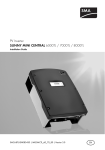
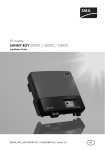
SUNNY BOY 3300TL HC
Installation Guide
SB3300TLHC-IEN094121 | IME-SB33TLHC | Version 2.1
EN
SMA Solar Technology AG
Table of Contents
Table of Contents
1
1.1
1.2
1.3
1.4
Notes on this Manual. . . . . . . . . . . . . . . . . . . . . . . . . . . . . .
Validity . . . . . . . . . . . . . . . . . . . . . . . . . . . . . . . . . . . . . . . . . . . .
Target group . . . . . . . . . . . . . . . . . . . . . . . . . . . . . . . . . . . . . . . .
Additional Information . . . . . . . . . . . . . . . . . . . . . . . . . . . . . . . .
Symbols Used . . . . . . . . . . . . . . . . . . . . . . . . . . . . . . . . . . . . . . .
2
2.1
2.2
Safety . . . . . . . . . . . . . . . . . . . . . . . . . . . . . . . . . . . . . . . . . . 7
Appropriate Usage . . . . . . . . . . . . . . . . . . . . . . . . . . . . . . . . . . . 7
Safety Instructions . . . . . . . . . . . . . . . . . . . . . . . . . . . . . . . . . . . . 8
3
3.1
3.2
Overview . . . . . . . . . . . . . . . . . . . . . . . . . . . . . . . . . . . . . . . 9
Identifying the Sunny Boy . . . . . . . . . . . . . . . . . . . . . . . . . . . . . . 9
External dimensions . . . . . . . . . . . . . . . . . . . . . . . . . . . . . . . . . . 9
4
4.1
4.2
Mounting. . . . . . . . . . . . . . . . . . . . . . . . . . . . . . . . . . . . . . . 10
Selecting the Mounting Location. . . . . . . . . . . . . . . . . . . . . . . . 10
Mounting the Sunny Boy. . . . . . . . . . . . . . . . . . . . . . . . . . . . . . 12
5
5.1
Electrical Connection . . . . . . . . . . . . . . . . . . . . . . . . . . . . . 14
Overview Connection Area . . . . . . . . . . . . . . . . . . . . . . . . . . . 14
5.1.1
View from Below . . . . . . . . . . . . . . . . . . . . . . . . . . . . . . . . . . . . . . . . . . . . . . 15
5.1.2
View from Inside . . . . . . . . . . . . . . . . . . . . . . . . . . . . . . . . . . . . . . . . . . . . . . 16
5.2
Low Voltage Grid (AC). . . . . . . . . . . . . . . . . . . . . . . . . . . . . . . 17
5.2.1
Connection of the AC Output . . . . . . . . . . . . . . . . . . . . . . . . . . . . . . . . . . . . 18
5.3
PV Generator Requirements . . . . . . . . . . . . . . . . . . . . . . . . . . . 19
5.3.1
PV string (DC) connection . . . . . . . . . . . . . . . . . . . . . . . . . . . . . . . . . . . . . . . 20
5.4
5.5
Setting the Display Language . . . . . . . . . . . . . . . . . . . . . . . . . . 22
The Communications Interface . . . . . . . . . . . . . . . . . . . . . . . . . 23
5.5.1
Connection RS485, Radio Piggy-Back . . . . . . . . . . . . . . . . . . . . . . . . . . . . . 24
5.5.2
Jumper Functions . . . . . . . . . . . . . . . . . . . . . . . . . . . . . . . . . . . . . . . . . . . . . . 25
Installation Guide
SB3300TLHC-IEN094121
5
5
5
5
6
3
Table of Contents
SMA Solar Technology AG
6
6.1
6.2
Commissioning . . . . . . . . . . . . . . . . . . . . . . . . . . . . . . . . . . 26
Display Message . . . . . . . . . . . . . . . . . . . . . . . . . . . . . . . . . . . 27
Blink Codes. . . . . . . . . . . . . . . . . . . . . . . . . . . . . . . . . . . . . . . . 28
7
Sunny Boy Opening and Closing . . . . . . . . . . . . . . . . . . . 29
7.1
7.2
Opening the Sunny Boy . . . . . . . . . . . . . . . . . . . . . . . . . . . . . . 29
Closing the Sunny Boy . . . . . . . . . . . . . . . . . . . . . . . . . . . . . . . 30
8
8.1
8.2
Maintenance and Cleaning . . . . . . . . . . . . . . . . . . . . . . . . 31
Cleaning the Cooling Fins. . . . . . . . . . . . . . . . . . . . . . . . . . . . . 31
Check the Electronic Solar Switch for wear . . . . . . . . . . . . . . . 31
9
9.1
Troubleshooting . . . . . . . . . . . . . . . . . . . . . . . . . . . . . . . . . 32
The red LED is continuously lit . . . . . . . . . . . . . . . . . . . . . . . . . . 32
9.1.1
Checking the PV Generator for Ground Fault . . . . . . . . . . . . . . . . . . . . . . . . 32
9.1.2
Checking the Function of the Varistors . . . . . . . . . . . . . . . . . . . . . . . . . . . . . 33
10
10.1
10.2
10.3
10.4
Decommissioning . . . . . . . . . . . . . . . . . . . . . . . . . . . . . . . . 35
Disassembly . . . . . . . . . . . . . . . . . . . . . . . . . . . . . . . . . . . . . . . 35
Packaging . . . . . . . . . . . . . . . . . . . . . . . . . . . . . . . . . . . . . . . . . 35
Storage . . . . . . . . . . . . . . . . . . . . . . . . . . . . . . . . . . . . . . . . . . . 35
Disposal . . . . . . . . . . . . . . . . . . . . . . . . . . . . . . . . . . . . . . . . . . 35
11
Technical Data . . . . . . . . . . . . . . . . . . . . . . . . . . . . . . . . . . 36
12
Accessories . . . . . . . . . . . . . . . . . . . . . . . . . . . . . . . . . . . . . 39
13
Contact . . . . . . . . . . . . . . . . . . . . . . . . . . . . . . . . . . . . . . . . 40
4
SB3300TLHC-IEN094121
Installation Guide
SMA Solar Technology AG
Notes on this Manual
1 Notes on this Manual
This manual describes the mounting, installation, commissioning and servicing of the SMA inverters of
the type Sunny Boy 3300TL HC (SB 3300TL HC). Store this manual where it will be accessible at all
times.
1.1 Validity
This manual is valid for the Sunny Boy 3300TL HC.
1.2 Target group
This manual is intended for the electrician.
1.3 Additional Information
You will find further information on special topics such as designing a line circuit breaker or the
description of the operating parameters in the download area at www.SMA.de/en.
Refer to the user manual for detailed information on troubleshooting and operating the Sunny Boy.
Installation Guide
SB3300TLHC-IEN094121
5
Notes on this Manual
SMA Solar Technology AG
1.4 Symbols Used
The following types of safety instructions and general information appear in this document as
described below:
DANGER!
DANGER indicates a hazardous situation which, if not avoided, will result in death or
serious injury.
WARNING!
WARNING indicates a hazardous situation which, if not avoided, could result in death or
serious injury.
CAUTION!
CAUTION indicates a hazardous situation which, if not avoided, could result in minor or
moderate injury.
NOTICE!
NOTICE indicates a situation that can result in property damage if not avoided.
Information
Information provides tips that are valuable for the optimal installation and operation of
your product.
6
SB3300TLHC-IEN094121
Installation Guide
SMA Solar Technology AG
Safety
2 Safety
2.1 Appropriate Usage
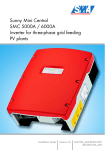
The Sunny Boy is a PV inverter that converts the DC current of solar cells to AC current and feeds it
into the public grid.
Principle of a PV system with this Sunny Boy
The Sunny Boy may only be operated with PV generators (modules and cabling) of protection class
II. Do not connect any sources of energy other than PV modules to the Sunny Boy.
PV modules with large capacities relative to ground, such as thin-film modules with cells on a metallic
substrate, are only to be implemented if their coupling capacity is below 50 nF/kWp.
During grid feeding, a leakage current whose magnitude depends on the manner in which the
modules are installed and on the weather (rain, snow) flows from the cells to ground. This operational
leakage current is not to exceed a value of 50 mA.
When designing the PV system, ensure that the values comply with the permitted operating range of
all components at all times. The free design program "Sunny Design"
(www.SMA.de/en/SunnyDesign) will assist you. The manufacturer of the PV modules must have
approved the modules for use with this Sunny Boy unit. You must also ensure that all measures
recommended by the module manufacturer for long-term maintenance of the module properties are
taken (see also Technical Information "Module Technology", in the download area of
www.SMA.de/en).
Do not use the Sunny Boy for purposes other than those described here. Alternative uses,
modifications to the Sunny Boy or the installation of components not expressly recommended or sold
by the manufacturer void the warranty claims and operation permission.
Installation Guide
SB3300TLHC-IEN094121
7
Safety
SMA Solar Technology AG
2.2 Safety Instructions
DANGER!
Danger to life due to high voltages.
• All work on the Sunny Boy must only be carried out by a qualified personnel.
CAUTION!
Danger of burn injuries due to hot housing parts!
• Do not touch the housing of the Sunny Boy during operation.
NOTICE!
Foreign objects or water entering the Sunny Boy can damage the device!
Once the Electronic Solar Switch has been pulled out, the Sunny Boy only provides
protection degree IP21. The Sunny Boy is then no longer protected against water and
contamination with dirt!
In order that the protection level IP65 is also provided during a temporary
decommissioning, proceed as follows:
• Unplug all DC plug connectors and seal them with the protecting caps provided.
• Attach the Electronic Solar Switch again.
Grounding the PV generator
Comply with the local requirements for grounding the modules and the PV generator. SMA
reccomends to electrically bond the module frames, the racks and all metal surfaces and
ground these in order to have optimal protection of the system and personnel.
8
SB3300TLHC-IEN094121
Installation Guide
SMA Solar Technology AG
Overview
3 Overview
3.1 Identifying the Sunny Boy
You can identify the Sunny Boy using the type label. The type label can be found on the right side of
the housing and contains information about the serial number, the device type as well as technical
data.
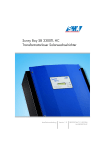
3.2 External dimensions
225 mm
470 mm
490 mm
Installation Guide
SB3300TLHC-IEN094121
9
Mounting
SMA Solar Technology AG
4 Mounting
4.1 Selecting the Mounting Location
DANGER!
Danger to life due to fire or explosion!
Despite careful construction, a fire can occur with electrical devices.
• Do not mount the Sunny Boy on flammable construction materials.
• Do not mount the Sunny Boy near highly flammable materials.
• Do not install the Sunny Boy in potentially explosive areas!
CAUTION!
Danger of burn injuries due to hot housing parts!
The temperature of individual parts of the housing, in particular the temperature of the
heatsink and the components inside the Sunny Boy can reach more than 60 °C. Touching
could result in burns!
Weight
CAUTION!
Risk of injury due to the heavy weight of the Sunny Boy!
The Sunny Boy weighs more than 28 kg.
• Consider the weight of the Sunny Boy when choosing the location and method of
installation.
Ambient Conditions
• The mounting location and mounting method must be suitable for the weight and dimensions.
• Mount on a solid surface.
• The installation location must be accessible at all times (do not mount in inaccessible places).
• The Sunny Boy must be easy to remove from the mounting location at any time.
• The Sunny Boy must not be in operation in ambient temperatures outside the range of -25 °C
and +60 °C. For optimal operation, the ambient temperature should not exceed +40 °C.
• Do not expose the Sunny Boy to direct sunlight, so as to avoid power reduction due to excessive
heating.
10
SB3300TLHC-IEN094121
Installation Guide
SMA Solar Technology AG
•
Mounting
In a living area, do not mount the unit on
plasterboard walls (or similar) in order to avoid
audible vibrations.
The Sunny Boy can make noises when in use which
can be regarded as a nuisance when installed in a
living area.
• Vertical installation or tilted backwards by max. 45°.
• Install at eye level to allow operating modes to be read at all times.
• Never install the device with a forward tilt.
• Do not install horizontally.
Safety Clearances
Observe the following safety clearances to walls, other devices or other objects in order to guarantee
sufficient heat dissipation and enough space for removing the Electronic Solar Switch:
Direction
Sides
Top
Bottom
Front
Installation Guide
Minimum Clearance
20 cm
20 cm
50 cm
5 cm
SB3300TLHC-IEN094121
11
Mounting
SMA Solar Technology AG
4.2 Mounting the Sunny Boy
To make the job easier, we recommend you use the
supplied wall bracket to mount the Sunny Boy. For
vertical installation on solid concrete or block walls, for
example, you can fit the bracket using 8 mm x 50 mm
hexagon bolts to DIN 571 standard, stainless steel type,
and with wall plugs type SX10.
When selecting the mounting materials, be sure to take
into account the weight of the Sunny Boy (28 kg).
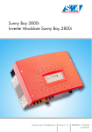
If you do not want to use the supplied wall bracket as a template, observe the dimensions shown in
the illustration below. The procedure for mounting the inverter using the wall bracket is described on
the following pages.
260 mm
95 mm
130 mm
395 mm
300 mm
105 mm
12
SB3300TLHC-IEN094121
Installation Guide
SMA Solar Technology AG
Mounting
1. Mount the wall bracket (1). In order to mark the
positions for the drill holes, you can use the wall
bracket as a drilling template.
2. Now hang the Sunny Boy onto the wall bracket (2)
using its upper mounting plate so that it cannot be
moved sideways.
3. Fix the Sunny Boy onto its bracket by screwing the
supplied M6x10 bolt into the central threaded hole
at the bottom of the bracket (3).
4. Make sure that the Sunny Boy is positioned
securely on the bracket.
Installation Guide
SB3300TLHC-IEN094121
13
Electrical Connection
SMA Solar Technology AG
5 Electrical Connection
5.1 Overview Connection Area
NOTICE!
Electrostatic discharges can damage the Sunny Boy!
Internal components of the Sunny Boy can be irreparably damaged by electrostatic
discharge.
• Ground yourself before you touch a component.
The complete wiring for a Sunny Boy is shown schematically in the following figure:
Opening for optional
communication
String 1
14
AC connection, max. 10 mm²
String 2
SB3300TLHC-IEN094121
Installation Guide
SMA Solar Technology AG
Electrical Connection
5.1.1 View from Below
Electronic Solar Switch (ESS)
socket
Plug and socket
connector for connection
of the solar modules
Installation Guide
AC plug for the mains
supply connection
Cable openings for optional
communication via RS485 or
radio (PG16)
SB3300TLHC-IEN094121
15
Electrical Connection
SMA Solar Technology AG
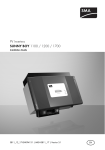
5.1.2 View from Inside
The following diagram gives a schematic overview of the various components and connection points
inside the Sunny Boy with the cover removed:
Object
A
B
C
D
E
F
G
H
I
J
K
L
Description
Socket for communication (RS485, radio), section 5.5 ”The Communications Interface”
(page 23)
Sunny Display
PE (protective earth) connecting cable for cover
Operating status LEDs
Connection terminals (AC), chapter 5.2.1 ”Connection of the AC Output” (page 18)
Tab for grounding the cable shield with RS485 communication
Socket for the PLC power module (required for mains grid communication)
Electronic Solar Switch (ESS) socket
PV input plugs (DC), section 5.3.1 ”PV string (DC) connection” (page 20)
Varistors, section 9.1 ”The red LED is continuously lit” (page 32)
Jumper slot for communication
Communication connector
16
SB3300TLHC-IEN094121
Installation Guide
SMA Solar Technology AG
Electrical Connection
5.2 Low Voltage Grid (AC)
Load Disconnection Unit
The maximal permissible rating is located in the technical data (page 36).
DANGER!
Danger to life due to fire!
When a generator (Sunny Boy) and a consumer are connected to the same line circuit
breaker, the protective function of the line circuit breaker is no longer guaranteed. The
current from the Sunny Boy and the grid can add up to overcurrent which is not detected
by the line circuit breaker.
• Never connect loads between the Sunny
Boy and the line circuit breaker without
protection.
• Always install separate fuses for loads.
The relevant technical regulations and the special instructions of the local grid operator must be
followed.
The connection terminals of the Sunny Boy are suitable
for wire cross-sections of up to 10 mm². The external
diameter of the cable must be between 9mm and 17mm.
The connection is made with three wires (L, N, PE).
Examples for the rating of a line circuit breaker can be found in the Technical Information
"line circuit breaker" in the download area of www.SMA.de/en.
The Sunny Boy is equipped with an integrated universal current sensitive leakage-current monitoring
unit. The Sunny Boy can automatically differ between real fault currents and "normal" capacitive
leakage currents.
The Sunny Boy does not generate any extraordinary leakage currents in normal operation. In certain
operating states (e.g. during self-test of the protective equipment), leakage currents may occur which
can trigger a "normal" 30 mA RCD or FI circuit breaker.
A 30 mA RCD or FI circuit breaker must not be installed.
In the event that an RCD or FI circuit breaker is necessary or mandatory, you must use a
circuit breaker with a tripping characteristic of 100 mA or more.
Installation Guide
SB3300TLHC-IEN094121
17
Electrical Connection
SMA Solar Technology AG
5.2.1 Connection of the AC Output
Connection requirements of the grid operator
Always observe the connection requirements of your grid operator!
To connect the AC cable, proceed as follows:
1. Check the grid voltage. Complying with DIN VDE 0126-1-1, the Sunny Boy will not be fully
operational if the grid voltage is constantly higher than 253 V. In this case, contact the local
grid operator for assistance. The inverter can temporarily feed power into the grid with a
maximum output voltage of 260 V. However, the 10-minute average must not exceed 253 V.
2. Isolate the grid connection (switch the line circuit
breaker to its "Off" position), make sure it cannot be
switched back on, and test to make sure no voltage
is present.
Off!
3. Remove the screws that secure the enclosure of the
Sunny Boy and carefully remove the cover. Remove
the PE connection from the cover.
4. Connect the mains cable as shown in the figure.
Use the supplied cable opening.
"L" and "N" must not be swapped.
5. Connect the protective earth (PE) of the power line
to the upper screw terminal with the earth sign.
6. Reconnect the PE connection to the housing cover
with these.
7. Fix the housing cover of the Sunny Boy and tighten
the four screws evenly.
18
SB3300TLHC-IEN094121
Installation Guide
SMA Solar Technology AG
Electrical Connection
Correct operation of your Sunny Boy requires, among other things, the connection of the
PE conductor to the equipotential bonding of the building. Please check the prescribed PE
connection from the Sunny Boy case to protective earth when commissioning the device!
DANGER!
Danger to life due to high voltages.
• Do not switch the line circuit breaker on yet! The Sunny Boy may only be connected
to the AC grid once the PV strings are connected and the device is securely closed.
5.3 PV Generator Requirements
The Sunny Boy is designed to be connected to up to two strings having a homogenous structure
(modules of the same type, identical orientation, tilt and number).
Sunny Design will assist you in the system design and checking of the string size for a given type of
inverter. Further information on Sunny Design is available at www.SMA.de/en.
The unit has four DC plug connectors (two for each string) for connecting the PV generators. The
connecting cables from the PV generators must also be fitted with this type of plug connector. The
SMA order codes for the various connectors are as follows [see also section 12 ”Accessories”
(page 39)]:
• Multi-Contact 3 mm:
• Multi-Contact 4 mm:
• Tyco:
Limit values for DC input
Max. voltage
Max. input current
Installation Guide
"SWR-MC"
"MC-SET"
"TYCO-SET"
750 V (DC)
11 A (DC)
SB3300TLHC-IEN094121
19
Electrical Connection
SMA Solar Technology AG
5.3.1 PV string (DC) connection
DANGER!
Danger to life due to high voltages on the Sunny Boy!
• Before connecting the PV generator, ensure that the line circuit breaker is switched
off.
Use of Adaptors
Adaptors (branch connectors) are not to be visible or freely accessible in the immediate
surrounding of the Sunny Boy, in order that the DC circuit is not disrupted as a result.
• Always disconnect the current flow first via the Electronic Solar Switch.
Procedure for DC connection
1. Remove the Electronic Solar Switch on the underside
of the Sunny Boy.
NOTICE!
Excessive voltages can destroy the measuring device!
• Only use measuring devices with a DC input voltage range up to at least 800 V.
2. Check that the PV generator connectors have the
right polarity and do not exceed the maximum
string voltage of 750 V (DC). See also section
5.1 ”Overview Connection Area” (page 14).
20
SB3300TLHC-IEN094121
Installation Guide
SMA Solar Technology AG
Electrical Connection
NOTICE!
Exceeding the maximum input voltage can destroy the Sunny Boy!
If the voltage of the PV modules exceeds the maximum input voltage of the Sunny Boy, it
can be destroyed by the overvoltage. All warranty claims become void.
• Do not connect strings to the Sunny Boy with open circuit voltage greater than the
maximum input voltage of the Sunny Boy.
• Check the system design.
3. Check the strings for ground faults, as described in
section 9.1.1 ”Checking the PV Generator for
Ground Fault” (page 32).
DANGER!
Risk of lethal electric shock!
• Do not connect any strings in which you have detected a ground fault!
• Firstly, clear the ground fault in the PV generator.
4. Connect up the faultless PV generator strings to the
inverter.
5. Close the unused DC input sockets with the caps
included in the delivery.
6. Reinsert the Electronic Solar Switch in the socket on
the underside of the Sunny Boy.
Installation Guide
SB3300TLHC-IEN094121
21
Electrical Connection
SMA Solar Technology AG
NOTICE!
Manipulating the connector in the handle can damage the Electronic Solar
Switch!
The connector within the handle must remain movable in order to ensure proper contact.
Tightening the screw voids all warranty claims and creates a fire risk.
• Do not tighten the connector screw in the Electronic Solar Switch handle.
NOTICE!
The Electronic Solar Switch can be damaged if it is inserted incorrectly!
The Electronic Solar Switch can be damaged by high voltage if it has not been attached
properly.
• Press the handle firmly into place on the socket of the Electronic Solar Switch until it
audibly locks into place.
• Check that the handle is securely in place.
5.4 Setting the Display Language
The display language of the display is set with the switches underneath the display assemblies inside
the Sunny Boy.
You can change the language setting of the display as follows:
1. Open the Sunny Boy as described in section 7.1 ”Opening the Sunny Boy” (page 29).
2. Set the switch combination of the required language. See Table.
Language
German
English
French
Spanish
Switch S2
B
B
A
A
Switch S1
B
A
B
A
3. Close the Sunny Boy as described in section 7.2 ”Closing the Sunny Boy” (page 30).
22
SB3300TLHC-IEN094121
Installation Guide
SMA Solar Technology AG
Electrical Connection
5.5 The Communications Interface
The communication interface is used to communicate with SMA communication devices (e.g. Sunny
Boy Control, Sunny WebBox) or a PC with appropriate software (e.g. Sunny Data Control).
Depending on the selected communication interface, up to 2500 inverters can be interconnected.
Detailed information on this topic can be found in the communication device manual, the software or
on the Internet at www.SMA.de/en.
For the installation of the communication interfaces there are the following possibilities:
• RS485, Funk Piggy-Back (see section 5.5.1 ”Connection RS485, Radio Piggy-Back”
(page 24))
The detailed wiring diagram for each communication interface can be found in the communication
device manual. This wiring diagram includes the following information:
• Details on the required cable type
• Which of the inverter's connections are used
• Whether jumpers need to be mounted, and if so, which jumpers
• Whether the PE needs to be connected to the cable shield
The next pages will describe the following:
• The housing feed-throughs for the communication interface
• The permitted cable route in the Sunny Boy
• The location of the PE connector
• The location of the screw terminals for connecting the communication wires
• The location of the jumper slots
• The location of the interface port
• The location of the interface port for the PLC power module and the Powerline modem
Installation Guide
SB3300TLHC-IEN094121
23
Electrical Connection
SMA Solar Technology AG
5.5.1 Connection RS485, Radio Piggy-Back
This section describes the installation of the Piggy-Backs for the different Sunny Boy communication
systems: RS485 interface and Radio Piggy-Back. You can take the relevant SMA order numbers from
the section 12 ”Accessories” (page 39).
NOTICE!
Electrostatic discharges can damage the Sunny Boy and the communication
interface!
Electrostatic discharges are an acute danger to the Sunny Boy and to the communication
interface.
• Ground yourself by touching PE before removing the communication interface from
the packaging, and before touching any components within the Sunny Boy.
Read the communication device manual before beginning installation work. Further wiring
details can be found there.
1. Open the Sunny Boy as described in section 7.1 ”Opening the Sunny Boy” (page 29).
2. Guide the PG screw fitting over the communication cable.
3. Thread the cable through one of the cable openings (A) on the Sunny Boy. Use one or two cable
openings, depending on the type of cable used. Use the right-hand housing feed-through for the
Radio Piggy-Back.
4. Screw the PG screw fitting onto the Sunny Boy.
5. Sheathe the cable inside the Sunny Boy using the silicone tube provided. The silicone tube is
imperative for safety reasons. The interface may not be commissioned without this silicone tube
(with the exception of the Radio Piggy-Back).
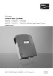
6. Lay the cable in area (B) as shown in the figure to the right.
7. Ground the cable shield at the PE connector (C) if the connection plan of the communication
device indicates this as necessary.
8. Connect the communication wires to the screw terminal strip (D) as described in the connection
plan of the communication device. Note down the connector color coding for the respective pin
numbers. Connecting the receiver incorrectly can damage the devices.
– Pin 2 color:
– Pin 3 color:
– Pin 5 color:
– Pin 7 color:
9. Connect the jumpers (E) if the connection plan of the communication device indicates this as
necessary. The table in section 5.5.2 ”Jumper Functions” (page 25) provides an overview of
the jumper functions.
24
SB3300TLHC-IEN094121
Installation Guide
SMA Solar Technology AG
Electrical Connection
10. Plug the communication interface to the left of the board (F).
11. Close the Sunny Boy as described in section 7.2 ”Closing the Sunny Boy” (page 30).
F
E
D
B
A
Enclosure openings in the base of the Sunny Boy.
B
Cable route (gray surface)
C
PE connector
D
Screw terminals for connection of the communication wires
E
Jumper slots
F
Interface port
A
C
5.5.2 Jumper Functions
RS485
Radio Piggy-Back
Jumper A
Termination
-
Jumper B
Bias 1
-
Jumper C
Bias 2
-
A detailed description of the jumper functiosn can be found in the communication device
documentation.
Installation Guide
SB3300TLHC-IEN094121
25
Commissioning
SMA Solar Technology AG
6 Commissioning
Check the following requirements before commissioning:
• The cover is securely screwed on.
• The AC (power) cable is connected correctly.
• The DC cables (PV-Strings) are fully connected.
• The unused DC plug connectors on the underside of the housing are sealed with protecting
caps.
• The Electronic Solar Switch (ESS) is correctly attached.
• The line circuit breaker is correctly rated.
Commissioning Procedure
1. Switch the line circuit breaker to the "On" position.
2. Now look at the LED display and consult the table
on the following page to check whether the Sunny
Boy is in a fault-free and expedient operating
mode. If this is the case, commissioning was
successfully completed.
26
SB3300TLHC-IEN094121
On
Operation
(green)
Ground fault
(red)
Disturbance
(yellow)
Installation Guide
SMA Solar Technology AG
Commissioning
6.1 Display Message
Feeding Operation
After fault-free grid connection of the Sunny Boy, it takes approximately one minute until the following
display messages are shown alternately. The display messages shown before only have the purpose
of indicating the initialization of the Sunny Boy and the process of controlling whether the power
supply requirements are fulfilled.
• Initially, the energy generated on the respective
day and the current operating mode are displayed.
• After 5 seconds or by tapping on the enclosure lid,
the current feed-in output and the output voltage
are displayed.
Pac
Vac
903W
230V
• After a further 5 seconds, or when you tap again,
the current input voltage and the input power are
displayed.
Vpv
Ppv
520V
1325W
• After a further 5 seconds, or when you tap again,
the total energy produced and the time the Sunny
Boy has been connected to the grid are displayed.
• Then the cycle begins again.
Disturbance
• In case of a failure, the message "Disturbance" will
be indicated in the status bar.
• The exact failure message follows.
• For example, if the grid fault message shown here
is displayed immediately after connection, it may
be due to the fact that the AC wire is not correctly
connected or the circuit breaker is not switched on
yet.
• If the disturbance was caused by a measured value
that does not correspond to the standard, the value
measured at the time of the disturbance is
displayed. If another measurement is possible, the
present value is displayed in the second line.
Installation Guide
SB3300TLHC-IEN094121
27
Commissioning
SMA Solar Technology AG
PV Overvoltage
NOTICE!
Excessive DC input voltage can destroy the Sunny Boy!
If the bottom yellow LED flashes four times at
intervals of one second, the grid voltage and the
PV generator must be immediately disconnected
from the Sunny Boy! There is a danger of
damage to the inverter resulting from excessive
DC input voltage!
Check the string voltages again to make sure they are within the limits stated in section 5.1 ”Overview
Connection Area” (page 14). If the input voltage is too high, contact the planner / installer of the PV
generator for assistance.
If despite checking the string voltages the LED signal occurs again when the PV generator is connected
to the Sunny Boy, disconnect the PV generator from the Sunny Boy again and contact SMA Solar
Technology (see section 13 ”Contact” (page 40)).
6.2 Blink Codes
Green
Glows continuously
Flashes quickly
(3 x per second)
Flashes slowly
(1 x per second)
Briefly goes out
(approx. 1x per
second)
Is not glowing
Red
Is not glowing
Glows continuously
Yellow
Is not glowing
Is not glowing
Glows continuously
Is not glowing
Is not glowing
Glows continuously
Is not glowing
Status
OK (feeding operation)
Disturbance
OK (initialization)
OK (Stop)
Disturbance
Is not glowing
Glows continuously
Is not glowing
Is not glowing
OK (waiting, grid monitoring)
Disturbance
Is not glowing
Glows continuously
Is not glowing
Is not glowing
OK (derating)
Disturbance
Is not glowing
Is not glowing
glowing/blinking
Is not glowing
glowing/blinking
OK (night shutdown)
Disturbance
Disturbance
Disturbance
Glows continuously
You will find a detailed description of the failure messages and their causes as well as the
meaning of the blink codes in the the Sunny Boy user manual included in delivery.
28
SB3300TLHC-IEN094121
Installation Guide
SMA Solar Technology AG
Sunny Boy Opening and Closing
7 Sunny Boy Opening and Closing
NOTICE!
Electrostatic discharges can damage the Sunny Boy!
Internal components of the Sunny Boy can be irreparably damaged by electrostatic
discharge.
• Ground yourself before you touch a component.
7.1 Opening the Sunny Boy
DANGER!
Danger to life due to high voltages.
• Before opening the Sunny Boy, switch the line circuit breaker off and make sure that
it cannot be switched back on.
1. Remove the Electronic Solar Switch.
2. Disconnect the PV generator from the Sunny Boy.
DANGER!
Danger to life due to unsafe disconnection from the PV generator!
A secure separation from the PV generator is only guaranteed after pulling off the
Electronic Solar Switch and all DC connectors.
• Remove all DC plug connectors to completely disconnect the PV generator from the
Sunny Boy.
3. Check whether all LEDs and the display have gone out.
DANGER!
Danger to life due to high voltages.
• Wait 15 minutes for the capacitors to discharge.
4. Remove the four screws from the housing cover and pull the cover forward smoothly. Remove
the PE connection from the cover by loosening the locking device of the PE connection on the
cover.
5. Verify the absence of voltage with respect to ground at the AC clamp with an appropriate
meter. If there is a voltage present, check the installation!
Installation Guide
SB3300TLHC-IEN094121
29
Sunny Boy Opening and Closing
SMA Solar Technology AG
7.2 Closing the Sunny Boy
1. Reconnect the protective earth (PE) to the housing cover.
2. Now secure the lid to the Sunny Boy by tightening the four screws evenly. The screws must be
tightened with approximately 4 Nm torque in order to guarantee the sealing of the housing.
3. Connect the PV generator. Ensure the assignment of the strings is correct.
4. Check the Electronic Solar Switch for wear, as
described in section 8.2 ”Check the Electronic
Solar Switch for wear” (page 31).
5. Reinsert the Electronic Solar Switch in the socket on
the underside of the Sunny Boy.
NOTICE!
Manipulating the connector in the handle can damage the Electronic Solar
Switch!
The connector within the handle must remain movable in order to ensure proper contact.
Tightening the screw voids all warranty claims and creates a fire risk.
• Do not tighten the connector screw in the Electronic Solar Switch handle.
NOTICE!
The Electronic Solar Switch can be damaged if it is inserted incorrectly!
The Electronic Solar Switch can be damaged by high voltage if it has not been attached
properly.
• Press the handle firmly into place on the socket of the Electronic Solar Switch until it
audibly locks into place.
• Check that the handle is securely in place.
6. Switch the line circuit breaker to the "On" position.
7. Now check whether the LED display on the Sunny
Boy indicates that the device is functioning
correctly.
30
SB3300TLHC-IEN094121
Operation
(green)
Ground fault
(red)
Disturbance
(yellow)
Installation Guide
SMA Solar Technology AG
Maintenance and Cleaning
8 Maintenance and Cleaning
Check the correct operation of the Sunny Boy at regular intervals.
Impurities such as dust or airborne blossoms can cause heat concentration that can lead to yield
losses. Also check the Sunny Boy and the cables for visible external damage. Undertake repairs if
necessary.
8.1 Cleaning the Cooling Fins
The heat dissipation of the product can be restricted by unclean cooling fins.
• Clean the cooling fins with a suitable, soft brush.
8.2 Check the Electronic Solar Switch for wear
To check the Electronic Solar Switch for wear, proceed as follows:
1. Remove the Electronic Solar Switch.
2. Check whether metal tongues inside the connector have a brown discoloration or are burned
off.
Metal tongues
☑ If all metal tongues are in acceptable condition (as illustrated above), the Electronic Solar
Switch can continue to be used.
☑ If at least one of the metal tongues has a brown discoloration or is completely burned off
(as illustrated below), proper functioning of the Electronic Solar Switch is no longer
guaranteed.
worn-out metal
tongues
3. Replace the defective Electronic Solar Switch, before you re-commission the Sunny Boy. You
can purchase replacements from SMA Solar Technology (see section 12 ”Accessories”
(page 39)).
Installation Guide
SB3300TLHC-IEN094121
31
Troubleshooting
SMA Solar Technology AG
9 Troubleshooting
The Sunny Boy is a complex high-technology device. As a result, the possibilities for fixing faults on
site are limited to just a few items. Do not attempt to carry out repairs other than those described here.
Use the SMA Solar Technology 24-hour replacement service and repair service instead.
9.1 The red LED is continuously lit
If the red LED of the status display is continuously on during operation, there is either a ground fault
in the PV generator or at least one of the varistors for the overvoltage protection is defective.
9.1.1 Checking the PV Generator for Ground Fault
1. Disconnect the Sunny Boy from both the DC and AC connections, as described in section
7.1 ”Opening the Sunny Boy” (page 29).
2. Measure the voltages between the plus and minus pole of a string against the ground potential.
If voltage is found, there is a ground fault in the corresponding string.
DANGER!
Risk of lethal electric shock!
In case of a ground fault, the PV generator may carry high voltages.
• Do not touch the frame of the PV generator.
• Wait until no voltage can be measured.
• Do not connect strings with ground faults to the Sunny Boy.
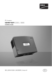
The approximate position of the ground fault can be determined from the ratio of the measured
voltages between plus against ground potential and minus against ground potential.
Example:
V1 = 40 V
20 V
20 V
V2 = 60 V
20 V
20 V
20 V
The ground fault is between the second and third module in this case.
32
SB3300TLHC-IEN094121
Installation Guide
SMA Solar Technology AG
Troubleshooting
3. Repeat step 2 for each string.
4. The table illustrated below shows the various results and corresponding measures.
Result
You have found a ground fault.
Measure
• The installer of the PV generator must remedy the
ground fault in the affected string before you may
reconnect the string to the Sunny Boy.
• Do not reconnect the faulty string.
You have found no ground fault.
• Close the Sunny Boy and operate as described in
section 7.2 ”Closing the Sunny Boy” (page 30).
It is likely that one of the thermally monitored varistors is
defective.
• Check the varistors as described in section
9.1.2 ”Checking the Function of the Varistors”
(page 33).
9.1.2 Checking the Function of the Varistors
Varistors are wearing parts. Their functioning becomes restricted through aging or due to repeated
responses as a result of overvoltages. It is therefore possible that one of the thermallly monitored
varistors has lost its protective functioning, and thus the red LED is permanently lit.
Position of varistors
The position of the varistors are to be determined with the help of the diagram below.
Observe the following allocation of the terminals:
• Terminal A: outer terminal
(varistor connection with crimp)
• Terminal B: middle terminal
• Terminal C: outer terminal
(varistor connection without crimp)
You can check the functioning of the varistors in the following manner:
1. Open the Sunny Boy as described in section 7.1 ”Opening the Sunny Boy” (page 29).
Installation Guide
SB3300TLHC-IEN094121
33
Troubleshooting
2.
SMA Solar Technology AG
Determine with the aid of a multimeter for both
varistors in the installed state whether a conductive
connection exists between connectors B and C
☑ If there is no conducting connection, then that
varistor is not working.
3. Replace both varistors, as illustrated in the adjacent
drawing, with new ones.
Ensure the varistor is installed the right way round!
If you do not receive a special tool for operating the
terminal clamps with your replacement varistors,
contact SMA Solar Technology. As an alternative,
the terminal contacts can be operated using a
suitable screwdriver.
Since the failure of one varistor is generally due to
factors that affect all varistors in a similar way
(temperature, age, inductive overvoltages), it is
highly recommended that you replace both
varistors. The varistors are specially manufactured
for use in the Sunny Boy and are not commercially
available. They must be ordered directly from SMA
Solar Technology (see section 12 ”Accessories”
(page 39)).
Insert the special tool to
open the terminal clamp
Remove the varistor
The pole with the crimp
must be fitted to terminal A
when reassembling.
NOTICE!
The Sunny Boy could be irreparably damaged by overvoltage!
If varistors are missing, the Sunny Boy is no longer protected against overvoltages.
• Replacement varistors should be obtained as soon as possible.
• The Sunny Boy must not be operated without varistors in systems with a high risk
of overvoltages.
4. Close the Sunny Boy as described in section 7.2 ”Closing the Sunny Boy” (page 30).
If no ground fault and no defective varistor were found, there is probably a fault in the Sunny Boy. In
this case, contact the SMA Serviceline to discuss what to do next.
34
SB3300TLHC-IEN094121
Installation Guide
SMA Solar Technology AG
Decommissioning
10 Decommissioning
10.1 Disassembly
1. Open the Sunny Boy as described in section 7.1 ”Opening the Sunny Boy” (page 29).
2. Remove all cables from the Sunny Boy.
3. Close the Sunny Boy: fasten the housing cover to the Sunny Boy with the 4 screws.
4. Loosen the cylinder head screw between the Sunny Boy and wall mounting bracket.
5. Dismantle the Sunny Boy by lifting it out of the wall mounting bracket.
10.2 Packaging
If possible, always package the Sunny Boy in the original packaging. If this is no longer available,
you can also use an equivalent box that fulfills the following requirements:
• Suitable for loads up to 28 kg
• With handle system
• Completely closable
10.3 Storage
Store the Sunny Boy in a dry place where ambient temperatures are always between -25 °C
and +60 °C.
10.4 Disposal
Dispose of the Sunny Boy at the end of its service life in accordance with the disposal regulations for
electronic waste which apply at the installation site at that time. Alternatively, send it back to SMA
Solar Technology with shipping paid by sender, and labeled "ZUR ENTSORGUNG" ("for disposal").
Installation Guide
SB3300TLHC-IEN094121
35
Technical Data
SMA Solar Technology AG
11 Technical Data
PV generator connection data
Setting
750 V a)
Max. input voltage
UDC max
Input voltage, MPP range
Upv
Max. input current
IPV max
Max. input power
PDC
3440 W
Voltage ripple
Upp
< 10 % of the input voltage
Internal consumption during operation
125 V ... 600 V
11 A
< 10 W (standby)
a) The maximum open circuit voltage, which can occur at a cell temperature of -10 °C, must not exceed the maximum input
voltage.
Grid Connection Data
Setting
Nominal output power
PACnom
3000 W
Max. output power
PACmax
3300 W
Nominal output current
IACnom
13 A
Max. output current
IAC max
16 A
Max. fuse protection
32 A
Harmonic distortion of output current
(at THD < 2 %, PAC > 0.5 PACNom)
KIAC
Nominal AC voltage
UACnom
Voltage range
(extended operating range)
UAC
AC- Grid frequency
fACnom
Frequency range
(extended operating range)
fAC
<4%
220 V / 230 V / 240 V
180 ... 260 V AC
50 Hz
45.5 ... 52.5 Hz
Power factor (at nominal output power) cos Phi
1
Overvoltage category
III
Test voltage (50 Hz)
1.65 kV
Test surge voltage
Internal consumption in night mode
36
SB3300TLHC-IEN094121
4 kV (serial interface: 6 kV)
0.25 W
Installation Guide
SMA Solar Technology AG
Technical Data
General Data
EC Declaration of Conformity
You will find the EC Declaration of Conformity in
the accompanying document set or in the
download area of www.SMA.de/en under
Certificate.
Protection category per DIN EN 60529
Dimensions (W x H x D)
IP65
approx. 470 mm x 490 mm x 225 mm
Weight
approx. 28 kg
Protection class
I
Topology
Transformerless
Climatic conditions according to DIN EN 50178:1998-04
Location of type C:
Class 4K4H
Extended temperature range: -25 °C ... +60 °C
Extended humidity range: 0 ... 100 %
Extended air pressure range: 70 kPa ... 106 kPa
Transport of type E:
Class 2K3
Temperature range: -25 °C ... +70 °C
Operating temperature range
-25 °C ... +60 °C
Max. operating altitude
2000 m above sea level NN
Noise emission (typical)
≤ 29 dB (A)
Protective function DC side
All-pole isolator on the DC input side
Overvoltage protection
Personal protection
Pole Confusion Protection
Electronic Solar Switch, DC plug connectors
Thermally monitored varistors
Ground fault monitoring (Riso > 1 MOhm)
via short-circuit diode
Protective function AC side
Short Circuit Proof
All-pole disconnection unit on grid side
Installation Guide
Grid-side via current regulation
Automatic disconnection device (grid guard 2.1),
double design
SB3300TLHC-IEN094121
37
Technical Data
SMA Solar Technology AG
Communication Interfaces
RS485 (galvanically isolated)
optional
Radio
optional
Electronic Solar Switch
Electrical lifetime (in the event of a short circuit,
with a nominal current of 30 A)
Maximum switching current
Maximum switching voltage
Maximum PV power
Protection rating when plugged
Protection rating in unplugged state
Efficiency
Max. efficiency
European standard efficiency
ηmax
ηeuro
min. 50 switching processes
30 A
800 V
Approx. 10 kW
IP65
IP21
96 %
94.6 %
Efficiency curve
38
SB3300TLHC-IEN094121
Installation Guide
SMA Solar Technology AG
Accessories
12 Accessories
You will find the corresponding accessories and replacement parts for your product In the following
overview. If needed, you can order these from SMA Solar Technology or your dealer.
designation
Replacement varistors
Electronic Solar Switch
RS485 upgrade kit
Radio upgrade kit
Bluetooth® Wireless
Technology upgrade kit
DC- Connection set
Multi-Contact 3 mm:
DC- Connection set
Multi-Contact 4 mm:
Tyco DC connection set
Installation Guide
Brief description
Set of thermally monitored varistors (2 pcs.)
including insertion tool
ESS handle replacement part
RS485 interface
Radio Piggy-Back for upgrading a Sunny Boy
for communication with Sunny Beam,
including antenna, coaxial cable, and PG
cable gland (metal)
Bluetooth Interface
SMA order number
MSWR-TV7
Multi-Contact adapter set 3,
max. flow current: 21 A
Multi-Contact adapter set 4,
max. flow current: 30 A
TYCO adapter set,
max. flow current: 30 A
SWR-MC
ESS-HANDLE:03
485PB-MS-NR
BEAMPB-NR
on request
MC-SET
TYCO-SET
SB3300TLHC-IEN094121
39
Contact
SMA Solar Technology AG
13 Contact
If you have technical problems concerning our products, please contact our Serviceline. We require
the following information in order to provide you with the necessary assistance:
• Inverter type
• Type and number of modules connected
• Communication
• Series number of the Sunny Boy
• Blink code or display of the Sunny Boy
SMA Solar Technology AG
Sonnenallee 1
34266 Niestetal, Germany
www.SMA.de
Serviceline
Inverters:
+49 561 9522 1499
Communication: +49 561 9522 2499
Fax
+49 561 9522 4699
E-mail:
[email protected]
40
SB3300TLHC-IEN094121
Installation Guide
SMA Solar Technology AG
Installation Guide
Contact
SB3300TLHC-IEN094121
41
Contact
42
SMA Solar Technology AG
SB3300TLHC-IEN094121
Installation Guide
SMA Solar Technology AG
Legal Restrictions
The information contained in this document is the property of SMA Solar Technology AG. Publishing its content, either partially or
in full, requires the written permission of SMA Solar Technology AG. Any internal company copying of the document for the
purposes of evaluating the product or its correct implementation is allowed and does not require permission.
Exclusion of liability
The general terms and conditions of delivery of SMA Solar Technology AG shall apply.
The content of these documents is continually checked and amended, where necessary. However, discrepancies cannot be
excluded. No guarantee is made for the completeness of these documents. The latest version is available online at www.SMA.de
or from the usual sales channels.
Guarantee or liability claims for damages of any kind are excluded if they are caused by one or more of the following:
• Damages during transportation
• Improper or inappropriate use of the product
• Operating the product in an unintended environment
• Operating the product whilst ignoring relevant, statutory safety regulations in the deployment location
• Ignoring safety warnings and instructions contained in all documents relevant to the product
• Operating the product under incorrect safety or protection conditions
• Altering the product or supplied software without authority
• The product malfunctions due to operating attached or neighboring devices beyond statutory limit values
• In case of unforeseen calamity or force majeure
The use of supplied software produced by SMA Solar Technology AG is subject to the following conditions:
• SMA Solar Technology AG rejects any liability for direct or indirect damages arising from the use of software developed by
SMA Solar Technology AG. This also applies to the provision or non-provision of support activities.
• Supplied software not developed by SMA Solar Technology AG is subject to the respective licensing and liability agreements
of the manufacturer.
SMA Factory Warranty
The current guarantee conditions come enclosed with your device. These are also available online at www.SMA.de and can be
downloaded or are available on paper from the usual sales channels if required.
Trademarks
All trademarks are recognized even if these are not marked separately. Missing designations do not mean that a product or brand
is not a registered trademark.
The Bluetooth® word mark and logos are registered trademarks owned by Bluetooth SIG, Inc. and any use of such marks by SMA
Solar Technology is under license.
SMA Solar Technology AG
Sonnenallee 1
34266 Niestetal
Germany
Tel. +49 561 9522-0
Fax +49 561 9522-100
www.SMA.de
E-Mail: [email protected]
© 2004 to 2009 SMA Solar Technology AG. All rights reserved
Installation Guide
SB3300TLHC-IEN094121
43
SMA Solar Technology AG
www.SMA.de