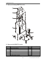
1
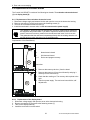
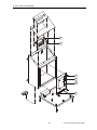
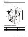
Operating Instructions
SENSITY Control Unit
9-18812 96th Avenue
Surrey, BC Canada, V4N 3R1
Tel: (001) 604 607-6028 Fax: (001) 604 607-6026
e-mail: [email protected]
1
TecTronix-Sensity-BA-CU-EN-3029.doc
Customer Name:
Location:
Date in Service d/m/y:
We would like to take this opportunity to thank you for purchasing your
Metal Detector from Tectronix. The confidence you have placed in our product
is sincerely appreciated and we will endeavour to provide the best service and
support possible.
Please take the time to read the User Manual completely as this provides
you with the expertise necessary to install and adjust the system according to
your requirements. In addition to this, you will learn about the sophisticated options provided by the SENSITY electronics.
If you have any problems in the set up and operation of your system, the
Tectronix team are available to assist you.
Tectronix Systems inc.
9 - 18812 Avenue
Surrey, British Columbia
Canada, V4N 3R1
Telephone: (001) 604 607-6028
Fax: (001) 604 607-6026
E-mail: [email protected]
2
TecTronix-Sensity-BA-CU-EN-3029.doc
Installation Do´s and Don´ts
Electrical
- Do Not cut the connector or the power cables
These cables are equipped with special double shields and connectors and must not be cut. If you require longer or shorter cables please order them from our parts department. The electrical cables are
approximately 10 feet (3m) in length and the connector cables are 26 feet (8m). It is therefore recommended that consideration be given to where the connection boxes are located and that all cables be
installed in conduit.
- Do Not weld in reasonable proximity to the metal detector
Welding in the vicinity of the metal detector will trigger faults.
-Run a clean, constant voltage power supply from the main to the control panel
Voltage fluctuations can cause false tripping therefore a constant voltage transformer is highly recommended.
- Do Not install the metal detector near MCC´s or control panels
Stray fields can trigger faults
- Run the connector cables to the metal detector separately
Connector cables are part of the metal detector and have to be protected against noise. It is highly recommended to run them in a dedicated conduit. Both cables can be run in the same conduit. The conduit should be metal but, must be grounded. If the conduit is to be connected at the transmit/receive
boxes on the coil and/or the control panel, all fittings must be plastic.
- Do Not install the detection coil inside an electromagnetic field
(strong power supply fluctuations) Interferences can trigger faults. For example; Where units are installed in close proximity to chipper motors, when under high amperage draw, can cause nuisance or
false tripping and this may require the fabrication of a shield.
- Do Not disconnect the metal detector from the power supply main
A constant, uninterrupted power supply enables more sensitive adjustments. Powering the unit on and
off causes it to recalibrate during which time metal will not be detected.
- When welding, do not use the control panel mounting surface as a ground
Mechanical
- Do Not use conductive (Anti-Static) belt material
Non-conductive belt material is preferred. When splicing belts, use a ”Finger over Finger” splice for
best results. Ensure all surfaces are clean and free of debris at the splice.
- Vibration less installation of the detector coil (except ”VT”)
Higher sensitivities can be attained and maintained if the operating conditions are optimal. Ensure the
coil is mounted to a structure that is stationery at all times.
- Eliminate loose metal to metal connections near or within the detection field
Intermittent metal to metal contacts from such things as roller axis, loose bolted connections, or broken
welds can cause the metal detector to false trip especially on the higher sensitivity settings.
- Vibration less installation of the Control Panel
Mount the control panel on a vibration free surface. Vibration can cause premature electronic component failure.
- Avoid cable whiplash……….
On “VT” Vibratory Conveyor installations, use the supplied cable clamps and tie wraps to secure the
cables to the metal detector housing. Doing so will avoid whip lash at the transmit/receive box strain relief connections. In addition to this we recommend that you loop the cables as they exit the conduit.
These loops will then flex as the conveyor cycles. It is also advisable to follow this procedure on belt
conveyor installations.
- Do Not touch the sensor/coil surface of the detector
Mechanical contacts may cause detection errors. Keep the sensing surface free of debris.
- Mount the FLAT PLATE type coils as close as possible to the underside of the vibrating conveyor or belt conveyor
The closer the coil to the product being conveyed, the greater the sensitivity.
- Isolate rollers on belt conveyors
On belt conveyor applications where a roller is less than 24” (610mm) from the centerline of the detector, the roller must be isolated on one side to avoid the possible effect of errant static charges. Use a
UHMW shim beneath the bearing and nylon washers or some other non conductive material beneath
the bolt head and nut/flat washer. The bolts should also be sleeved with a non conductive material.
3
TecTronix-Sensity-BA-CU-EN-3029.doc
Contents
Contents
1
2
3
General information
6
1.1
1.2
1.3
1.4
6
6
6
6
Technical data
7
2.1
2.2
Performance data
Dimensions
2.2.1 SENSITY standard version
2.2.2 SENSITY-D version
7
8
8
8
Design and method of operation
9
3.1
3.2
4
5
6
7
Field of application
Symbols used
Legal basis
Overall view
Functional principle
Functional and control elements
3.2.1 Electronic board
9
9
10
Safety
11
4.1
4.2
4.3
4.4
4.5
4.6
4.7
4.8
11
11
11
11
11
11
11
11
Use to the intended purpose
Marking of dangers
Risks in case of non-observance of the safety notes
Safety notes for the operator
Safety notes for operation and maintenance
Notes on residual risks
Consequences of unauthorized modification
Inadmissible operation
Commissioning
12
5.1
5.2
12
12
12
12
13
13
13
14
15
Mechanical installation
Connection of the equipment
5.2.1 Connector assignments of the electronic board
5.2.2 Electrical connection
5.2.3 Electrical rating
5.2.4 Mains supply
5.2.4.1 Connection with shock proof plug
5.2.4.2 Connection by clamp connection
5.2.5 Starting status of the equipment
Menu structure
16
6.1
6.2
6.3
6.4
16
17
18
19
Main menu (Operating level 1)
Setting menu (operating level 2)
System function menu (operating level 3)
Output configuration menu (operating level 4)
Operation
20
7.1
21
21
21
21
23
23
23
23
23
23
23
7.2
Main menu
7.1.1 Operating mask
7.1.2 Change product
7.1.3 Learn product
7.1.4 Settings
7.1.5 Device information
Menu settings
7.2.1 Code
7.2.2 Product name
7.2.3 Product angle
7.2.4 Sensitivity
4
TecTronix-Sensity-BA-CU-EN-3029.doc
Contents
7.3
7.4
7.5
8
10
24
24
24
24
25
25
25
25
25
25
26
26
26
26
26
27
27
27
27
27
28
28
29
Error and error remedying
30
8.1
30
30
30
30
31
31
31
31
32
32
33
33
33
8.2
8.3
8.4
9
7.2.5 Reject duration
7.2.6 Reject delay time
7.2.7 Metal reset
7.2.8 Setup
Menu device information
7.3.1 Metal counter
7.3.2 Check of conveying speed
7.3.3 Software version
Menu system functions
7.4.1 Conveying speed
7.4.2 Deviation frequency
7.4.3 Code change product
7.4.4 Code learn product
7.4.5 Code settings
7.4.6 Language
7.4.7 Half wave
7.4.8 Reset metal counter
7.4.9 Display
7.4.9.1 Display contrast
7.4.9.2 Display backlight
7.4.9.3 Display temperature
7.4.10 Save product data
Menu output configuration (operating level 4)
Error messages
8.1.1 Defective transmitter
8.1.2 Receiver voltage too high
8.1.3 Receiver connection
8.1.4 Error at the solenoid valve MV1 or MV2
8.1.5 Compressed air
8.1.6 Thermo monitor
8.1.7 Level monitor
Undefined activation of the outputs
Special notes on separators
Replacement of electronic boards
8.4.1 Replacement of the evaluation electronics board
8.4.2 Replacement of the display board
Spare parts, service
35
9.1
9.2
9.3
9.4
9.5
35
35
36
36
37
Spare parts drawing SENSITY standard version
Spare parts list SENSITY standard version
Spare parts drawing SENSITY-D version
Spare parts list SENSITY-D version
Service address
Shipping, transport, storing, preservation
5
38
TecTronix-Sensity-BA-CU-EN-3029.doc
1. General information
1 General information
1.1 Field of application
•
•
•
•
Product liability
ISO 9000
TQM (Total Quality Management)
Protection of consumers and of machines
1.2 Symbols used
= Important notes
= Danger notes
= Safety notes
Warning signs attached at the equipment:
These labels should call the readers attention to the text of the warning signs.
Danger!
This symbol refers on risks for life and health on account of electric voltages.
Danger!
This symbol refers on risks for life and health on account of electric voltages.
Danger!
This symbol refers on risks for life and health on account of electric voltages.
1.3 Legal basis
This equipment complies
• with EMC guideline 89/336/EC and 92/31/EC
• low-voltage guideline 73/23/EC
1.4 Overall view
SENSITY standard version
SENSITY-D version
SENSITY front panel
6
TecTronix-Sensity-BA-CU-EN-3029.doc
2. Technical data
2 Technical data
2.1 Performance data
Type
Control Unit „SENSITY“
Housing versions
SENSITY: Mild steel, varnished, FDA white, suitable for food (RAL 9010)
SENSITY-D: Stainless steel 1.4301 (AISI 304), glass bead blasted
Weight
5 kg
Connecting cable
(to the detection coil) up to 3 m standard (max. 15 m)
Mains cable
1,8 m with plug
Ambient temperature
-10...+50°C
Type of protection
IP 65
Power supply
100-240 VAC (±10%), 50/60 Hz
Current consumption
220mA/115V, 110 mA/230V
Fuse
1,6A, slow-blowing
Inputs
1 switching input „Reset“
1 switching input „air pressure monitor“ or „thermal switch“ or „level
indicator“
2 switching inputs for proximity switches
Outputs
2 relay output for metal alarm
1 relay output for error message
2 switching output 24V DC, 200mA for metal detection
Operation
Operator panel with:
Character display double spaced, 4-key operation
Reset/Test button
Lamp „operation“
Lamp „fault“
Lamp „metal“
Conveyance speed
depend on type and size of the detection coil used
Can be combined with
detection coils of the series RECTANGULAR, SQUARE, ST-VT, FLAT
PLATE and OCTAGONAL
Subject to changes due to technical innovation!
7
TecTronix-Sensity-BA-CU-EN-3029.doc
2. Technical data
2.2 Dimensions
2.2.1 SENSITY standard version
240
220
200
300
260
95
85
Ø9
2.2.2 SENSITY-D version
280
260
240
145
315
240
7
All dimensions in mm
8
TecTronix-Sensity-BA-CU-EN-3029.doc
3. Design and method of operation
3 Design and method of operation
3.1 Functional principle
Detec tion c oil
Re
c
e iv
er
Control Unit Sensity
Tra
nsm
itte
r
Re c
Computer
Signa l amplifier
eiv
er
Data
Analog / digital
c onverter
Data
Digita l signa l
proc essing
LCD displa y
Keyboard
Quartz osc illator
Relay
24V outputs
24V inputs
Outp ut
c ontrol
Monitoring
Power
supply
Memory for
28 produc ts
A metal impurity in the material flow causes a change of the high-frequency field in the detection coil.
This change is detected by the Control Unit. Since the product flow itself may already have an influence on the field (which is referred to as a product effect), this behaviour can be stored in order to
avoid false activation caused by the product effect. For this purpose the equipment offers 28 storage
places for different products.
3.2 Functional and control elements
The control panel of the SENSITY equipment has the following control and indication elements.
M E TA L D E TE C TO R
1
Be t rie b
o p e ra t io n
4
St ö ru n g
f a u lt
Re s e t
Te s t
ESC
5
M e t a ll
m etal
6
2
1
2
LCD display
Operator keys
3
4
5
6
Function key
Green lamp
Red lamp
Yellow lamp
3
double spaced, 32-digit display
ESC, UP, DOWN und
Reset / Test
Betrieb (operation)
Störung (fault)
Metall (metal)
to operate and set the equipment
to operate and set the equipment
resetting of the metal and alarm
lights up when mains supply is ON
blinks in case of fault or error
lights up in case of metal detection
9
TecTronix-Sensity-BA-CU-EN-3029.doc
3. Design and method of operation
3.2.1 Electronic board
The drawing below shows the position of the most important components and the placing of the connectors.
10
17
15 16
18
8
14 13
19
20
21
23
11
12
22
9
1
Connectors and terminals:
Elements connected to
mains voltage:
Elements connected to external voltage:
Memory devices:
LED s:
Test points:
2
3
(1)
(2)
(3)
(4)
(5)
(6)
(7)
(8)
(1)
(9)
(2)
(3)
(4)
(10)
(11)
(12)
(13)
(14)
(15)
(16)
(17)
(18)
(19)
(20)
(21)
(22)
(23)
4
5
6
21
7
„Mains“:
Power supply
„Metal 1“:
Potential-free change-over-contact
„Fault“:
Potential-free change-over-contact
„Metal 2“:
Potential-free change-over-contact
„Input/Output“
24V Inputs/Outputs
„Receiver“
Input signal from the detector coil
„Transmitter“
Output signal to the detector coil
Ribbon cable connector for control panel
„Mains“ connector
Mains fuses
„Metal 1“ connector
„Fault“ connector
„Metal 2“ connector
Device and product data
Status indication magnetic valve 1 (MV1)
Status indication magnetic valve 2 (MV2)
Active light supply voltage +5V
Active light supply voltage +24V
Active light supply voltage +15V
Active light supply voltage -15V
Supply voltage +5V
Supply voltage +24V
Supply voltage +15V
Supply voltage –15V
Common ground for all signals (GND)
Sine wave signal to the detection coil (transmitter)
Sine wave signal from the detection coil (receiver)
10
TecTronix-Sensity-BA-CU-EN-3029.doc
4. Safety
4 Safety
4.1 Use to the intended purpose
The equipment is intended to be used for the following fields of application only in combination
with a corresponding detection coil: Suction/pressure conveyance, free-fall applications, and use
in a conveyor belt. The ambient temperature of the equipment must not exceed 50°C. At the
operation field of the device, no steam (e.g. plasticizer) or other substances may occur that attack cord insulation of PVC.
4.2 Marking of dangers
Inside the electronic housing of the Control Unit SENSITY mains voltage is used and possibly connected external electric circuits may use also mains voltage.
Therefore on the cover of the electronic housing the warning sign is sticked.
Marking of terminals "Mains" with
(1)
, "Metal" and "Fault" with
(2)
(3)
If the covering have to be removed during maintenance and repair works notice the references in
4.5.
4.3 Risks in case of non-observance of the safety notes
In case of non-observance of the safety notes there is a danger for life and health on account of
electric voltages.
4.4 Safety notes for the operator
The control unit SENSITY may only be operated in the intended purpose and in a perfect functioning condition, especially the cover of the electronic housing has to be closed during operation. Entered moisture have to be removed! All fixed warning signs on the equipment may not be
removed and have to be in a well recognizable condition. The operating instructions always have
to be in a legible condition and complete available. The operator may only appoint qualified personnel for operation, maintenance and repair work. People with cardiac pacemaker should not
permanently stay in the area of the detection coil. If potentially explosive materials are examined, the pertinent regulations must be observed.
4.5 Safety notes for operation and maintenance
Clean the case of pollution and wetness so far before opening the cover of the electronic housing, that no greater lots reach the interior. Turn off power supply and connected circuits before
opening of the control cabinet. Entered moisture have to be removed!
The operator may only appoint qualified personnel for operation, maintenance and repair work.
4.6 Notes on residual risks
External circuits can still lead voltage in spite of interrupted mains power supply.
4.7 Consequences of unauthorized modification
In case of unauthorized modification or repair work all the declarations and guarantees given by
the manufacturer will become void.
4.8 Inadmissible operation
For other applications as enumerated in 4.1 the control unit SENSITY intended for – that is regarded as inadmissible operation. Inadmissible is the operation out of the specifications given in
the technical data and the operation under high mechanical static or dynamic loads (e.g. heavy
system parts or strong vibrations). Also inadmissible is the examination of aggressive materials
such as materials containing alkaline solutions, acids and solvents as well as the use in an explosion hazardous environment.
11
TecTronix-Sensity-BA-CU-EN-3029.doc
5. Commissioning
5 Commissioning
5.1 Mechanical installation
• Ensure stable and non-vibrating installation! In house mounting and operation. Do not install the
system in an explosion proof zone.
• Do not install the detection coil and the electronic unit in the vicinity of interference fields (e.g.
large electric motors and frequency converters)! The distance depends on the output of the motor
or of the frequency converter (value for orientation: 5 m).
• Mount the control cabinet by using the provided bores. i.e. at a wall or frame (dimensions are
shown in the outline drawings). Pay attention to good stability, as the weight of the control unit is
approx. 5kg.
• Never install the electronic unit in other switchgear cabinets, because this may lead to interference
effects (e.g. from contactor controls)!
• Cable lengths between electronic unit and detection coil may only be modified after consultation
with Tectronix. Always use original cables. Lay these connecting cables in fixed installation, apart
from other cables (e.g. fix them with nailing clips or lay them in a separate cable duct).
• If several metal detector systems are used, the distance of the detection coils must not be less
than 2 m, if these coils stand side by side. If the coils are arranged opposite to one another, the distance must not be less than 10 m. These values apply to large systems; for smaller systems the
distances may be reduced to 0.5 m. If, for reasons of space, these distances cannot be observed,
please contact "Tectronix" service!
5.2 Connection of the equipment
Cable
For CE conformity it is an absolute necessity to use shielded cables
for all the wires leading to the outside. The shields must be attached Shield
to the housing directly at the glands.
Housing
5.2.1 Connector assignments of the electronic board
5.2.2 Electrical connection
Connector
Connection
Description
„Mains“
Connection for power
supply
Potential-free relay
contact
Potential-free relay
contact
Potential-free relay
contact
As a standard a mains plug with integrated filter is already connected here.
Normal operation:
Contact 31 and 32 is closed
Metal detected:
Contact 31 and 34 is closed
Normal operation:
Contact 21 and 24 is closed
Fault signal:
Contact 21 and 22 is closed
Normal operation:
Contact 11 and 12 is closed, conveyor
belt running
Fault signal:
Contact 11 and 14 is closed, conveyor
belt stop
24V Inputs/Outputs
1,2
„Metal 1“
„Fault“
„Metal 2“
„Input/Output“
24V switching output MV1, remove the bridge
between 1-2 if you connect a external load
12
TecTronix-Sensity-BA-CU-EN-3029.doc
5. Commissioning
(valve)
Input for external reset button
Input for air pressure monitor, thermal switch,
level indicator
Input external +24V
Sensor 2 (PNP)
Sensor 1 (PNP)
24V switching output MV2, remove the bridge
between 15-16 if you connect a external load
(valve)
3,4
5,6
7,8
9,10,11
12,13,14
15,16
Connection for detec- 1
tion coil:
2
Receiver
3
4
5
Connection for detec- 1
tion coil:
2
transmitter
3
„Receiver“
„Transmitter“
Receiver signal
Reference ground for receiver
-15V
+15V
Transmitter signal 1
Reference ground for transmitter
Transmitter signal 2
5.2.3 Electrical rating
Dry relay contacts
24V DC Switching output
Control Inputs
250VAC / 3A
120VDC / 3A
Max. current load: 200 mA
Connection of make contacts against ⊥ or+ 24V, resp.
PNP outputs (NPN on request)
Switching elements (contactors, relays, etc.) may only be connected to the potential-free
contacts in interference-suppressed condition!
Relay connection for machine protection:
For the conveyor system to stop both in case of metal detection and in case of an error, the relays ”Metal” and ”Fault” must
be connected in series (see sketch at the right)!
Metal 1
Fault
34 31 32
24 21 22
Wire jumper
Connec tion c ontac ts
5.2.4 Mains supply
5.2.4.1 Connection with shock proof plug
1. Connect the power cord with shockproof plug to an existing mains outlet.
2. After approx 5 sec the system is ready for work.
13
TecTronix-Sensity-BA-CU-EN-3029.doc
5. Commissioning
5.2.4.2 Connection by clamp connection
The work described below may only be performed by qualified expert personnel ! Make
sure before opening the housing that no mains voltage or external voltage is applied to
the electronic unit!
The power cable and skintop gland may not be removed - it is an essential part of the
EMC-concept.
The power supply cable is special cable with ferrite shell and my not be replaced by a
standard shielded cable.
If the mains plug cannot be used, a connection box should be used.
1. Remove the mains plug.
2. Strip the insulation of the cable for 5 cm (2“) and of the wires for 1 cm (0.4“) and sheathe them.
Mains cable
1
5
4
2
3
1
Shield
2
Conductor
3
PVC - insulation
4
Shield
5
Sheath
3. Connect the cable according to the sketch below.
Make sure, that the mains voltage is switched off.
1
2
5
3
L
N
PE
6
7
8
Important!!!
4
1
2
3
4
5
6
7
8
Terminal box
3 pole terminal strip
Mains cord of control unit
Mains supply
Conductor L (brown)
to terminal
Conductor N (blue)
to terminal
Conductor PE (yellow/green) to terminal
Shield
to terminal
L
N
PE
PE
Connect the shield to PE
4. Close the terminal box.
5. Approx after 5 sec after switching on the unit is ready for operation.
Note:
The power cable has a wire cross-section from 0,75 mm². The safeguard of the AC power cable
should be designed correspondingly.
One spare piece of mains fuse are on the electronic board SENSITY.
14
TecTronix-Sensity-BA-CU-EN-3029.doc
5. Commissioning
5.2.5 Starting status of the equipment
Status of the lamps and outputs during the starting phase:
Lamp/output
Green lamp
Red lamp
Yellow lamp
Metal relay 1
Fault relay
Metal relay 2
24V switching outputs
MV1 / MV2
Contact status
on
on
on
Contacts 31 und 34 is closed (corresponds with metal detection)
Contacts 21 and 22 is closed (corresponds with fault status)
as programmed
„start = on”, contacts 11 and 14 is closed
„start = off”, contacts 11 and 14 is open
as programmed
H-active 0V
L-active 24V
Status of the lamps and outputs after the starting phase:
The SENSITY equipment is ready for operation after approx. 5 seconds. The display changes to the
operation mask.
Lamp/output
Green lamp
Red lamp
Yellow lamp
Metal relay 1
Fault relay
Metal relay 2
24V switching outputs
MV1 / MV2
Contact status
on
off
off
Contacts 31 and 34 is closed
Contacts 21 and 24 is closed
as programmed
„operation = on”, contacts 11 and 14 is closed
„operation = off”, contacts 11 and 14 is open
as programmed
H-active 0V
L-active 24V
15
TecTronix-Sensity-BA-CU-EN-3029.doc
6. Menu structure
6 Menu structure
6.1 Main menu (Operating level 1)
Operating mask
mask only when c ustomer code
is activates
mask only when c ustomer code
is activates
Setting menü
(see next page)
16
TecTronix-Sensity-BA-CU-EN-3029.doc
6. Menu structure
6.2 Setting menu (operating level 2)
mask only when c ustomer code
is activates
17
TecTronix-Sensity-BA-CU-EN-3029.doc
6. Menu structure
6.3 System function menu (operating level 3)
18
TecTronix-Sensity-BA-CU-EN-3029.doc
6. Menu structure
6.4 Output configuration menu (operating level 4)
-
19
TecTronix-Sensity-BA-CU-EN-3029.doc
7. Operation
7 Operation
General information for operation
•
•
•
•
•
To operate the SENSITY use the buttons UP, DOWN, ENTER and ESC.
The buttons are used to select menus or set and adjust parameters.
The button ESC always gets to the main menu.
The button Reset/Test allows to reset a metal alarm in the mode „manual“.
The program automatically returns to the main menu after 30 sec if no operation has been made.
Masks on the display
1. Operation mask: displayed during normal operation. Four different operation masks can be selected. Select them by pressing continuously the ESC button and select with UP
Example for an operation mask
bar graph for
metal signal
threshold
button allocation
2. Menu selection: use the buttons UP/DOWN to select the desired menu,
then confirm by pressing .
3.
operation level
button allocation
Main menu
Settings
Setup
Operation level > 1 <
Operation level
Operation level > 3 <
Operation level > 4 <
> 1a <
>2<
> 3a < > 3b < (system functions)
(output configuration)
Setting mask: Use the buttons UP / DOWN to set or change the parameters. The new settings
are stored by pressing . If the ESC- button is pressed after a changing the previous setting is effective.
Example for a setting mask
parameter setting
button allocation
20
TecTronix-Sensity-BA-CU-EN-3029.doc
7. Operation
7.1 Main menu
7.1.1 Operating mask
In the normal system operating mode, the operating mask is displayed. It is possible to use 4 different
operating masks. Change the operating mask by keeping pressed the ESC key and select by the UP
key.
Operating mask 1:
Displayed information
Operating mask 2:
Displayed information
Operating mask 3:
Displayed information
Operating mask 4:
Displayed information
Current product number
Metal signal as bar display
Current product number
Metal signal as bar display
Actual product number
S:
Threshold
M:
Metal signal
Actual product number
S:
Threshold
M:
Metal signal
In the case of a metal detection, the metal signal is held for a short time with the max.
value as a bar or as a measuring value (e.g.: M:0.8).
7.1.2 Change product
Select the menu “Change product” by pressing the
key
If the customer code has been set, input CODE
(otherwise, this mask is no longer displayed)
Select the desired product by pressing the UP / DOWN keys and confirm
by
7.1.3 Learn product
Select the menu “Learn product” by pressing the
key
If the customer code has been set, input CODE
(otherwise, this mask is no longer displayed)
The product teach-in process is carried out in two steps:
1. Product compensation by automatic determination of the optimum product angle
21
TecTronix-Sensity-BA-CU-EN-3029.doc
7. Operation
2. Adjustment of the maximum sensitivity with the product
1. Product compensation
Convey product through the detector head.
The displayed number is used as product counter. It displays how often
the product to be learned has passed the detector head.
Convey product with a large product effect until the system has compensated the product effect, then continue with the
key
>>>:
signals products with a large product effect, product effect
not compensated
Note: As long as the unit tries to compensate a product the teach-in procedure cannot be quit.
After product compensation the product counter is set to >1.
Product effect has been adapted. The determined product angle is
key.
adopted via the
>:
signals that product effect has been adapted
2. Maximum sensitivity setting
Convey the product at least once and finish the teaching process by the
key. The device automatically adjusts the max. Sensitivity with the product.
Both masks are displayed by turns.
Special case: Product effect too large!!!
This message is displayed if it was not possible to mask out the product
effect. The automatic teaching process must be repeated, since probably
an unexpected malfunction has occurred.
Possible reasons for unsuccessful teach-in procedure:
Reason:
Remedy:
Vibration of the detector coil during Repeat teach-in procedure
teach-in procedure
Metallic contaminants in product
Ensure that metal-free product is
used for teach-in procedure and repeat.
Several trials without success:
Ask Tectronix service for help. Send
Product effect can not be compen- test sample of the product.
sated
To get optimum product compensation, which results in optimum sensitivity, pay attention to the following:
• The real conveying speed must correspond with the rate, which was set at Setup (deviation
max. ± 20%).
• During product teach-in procedure the products must be conveyed always in the same direction.
• For products conveyed piece by piece each step must be repeated minimum 2 times. Better
results are achieved with several repetitions to average product straggling.
For products conveyed continuously wait, as a thumb rule, that the product has passed 5 x of
the detector length before confirming and initializing the next step.
• Avoid vibrations during teach- in procedure. Vibrations would considerably affect the results!
22
TecTronix-Sensity-BA-CU-EN-3029.doc
7. Operation
7.1.4 Settings
Select the menu “Settings” by pressing the key.
The submenus will be explained at a later time!
7.1.5 Device information
Select the menu “Device information” by pressing the
The submenus will be explained at a later time!
key.
7.2 Menu settings
7.2.1 Code
If the customer code has been set, input CODE
(otherwise, this mask will not be displayed)
7.2.2 Product name
Select the menu “Product name” by pressing the key. Here, a ten-digit
name can be given or changed for the current product.
Letters, numbers and various symbols can be selected via the UP /
DOWN keys. Via , a selected symbol is taken over and the cursor advances by one position. This is repeated until the end of line is reached.
7.2.3 Product angle
Select the menu “Product angle” by pressing the key. Here, it is possible to set or change the angle for the current product.
Via the UP / DOWN keys, it is possible to adjust the angle between 0.0°
and 180.0°. Via , the set angle is taken over.
M = Metal signal, supports the manual adjustment of the product compensation.
The adjustment is best when the smallest number (M:x.xx) is displayed.
7.2.4 Sensitivity
Select the menu “Sensitivity” by pressing the key. Here, the key sensitivity for the current product can be set or changed.
Via the UP / DOWN keys, it is possible to adjust the sensitivity between 1
and 100 %. Via , the adjusted value is taken over.
Metal signal displayed as a bar graph supports the sensitivity adjustment.
23
TecTronix-Sensity-BA-CU-EN-3029.doc
7. Operation
7.2.5 Reject duration
Select the “Reject duration” menu by pressing the key. Here, it is possible to set or change the time for the activation of the switch outputs.
Via the UP / DOWN keys, it is possible to adjust the reject duration to a
value between 0.05 sec and 30.0 sec. Via , the set value is taken over.
In the "menu" reset mode, this value is of no importance.
7.2.6 Reject delay time
Select the menu “Reject delay time” by pressing the key. Here, the
time between the conveyor section between metal detection and activation
of the switch outputs can be set or changed.
This mask is only active in the conveyor belt mode and is not displayed for the other operating mode.
It is possible to set the reject delay time to a value between 0.00 sec and
30.0 sec via the UP / DOWN keys. Via , the set value is taken over.
7.2.7 Metal reset
Select the menu “Metal reset” by pressing the key. Here, it can be adjusted whether the metal outputs are to be reset manually or automatically
(after setting the reject duration).
This mask is only active in the conveyor belt mode and is not displayed for the other operating modes.
It is possible to adjust one of the reset types Auto and Manual via the UP
/ DOWN keys. The adjustment is taken over via the key.
7.2.8 Setup
The menu „Setup“ is selected by pressing the
button.
Entering preset access code numbers allow to branch to additional
menus.
Code-no.: 3080, operating level 3, system functions
Code-no.: 4513, operating level 4, output configuration
24
TecTronix-Sensity-BA-CU-EN-3029.doc
7. Operation
7.3 Menu device information
7.3.1 Metal counter
Select the menu “Metal counter” by pressing the
key.
Here, the metal detections are counted and displayed. Via , the mask is
closed.
Reset the counter:
- The counter can be reset via the menu “System functions”.
- Pressing the function key “Reset / Test”, 5 sec without interruption.
7.3.2 Check of conveying speed
(precondition: half wave evaluation: NO)
This feature allows a rough check of the conveying speed and is now exact measuring device.
Select the menu “Conveying speed” by pressing the
key.
The current conveying is displayed, if a test piece is passed through
the detector head.
The display is updated by the metal signal.
The DOWN button resets the displayed speed to 0.0 m/sec.
(possibly repeat the procedure several times).
The displayed speed in m/sec should be compared with the set speed parameter in operation level 3, submenu „System functions“, menu “Conveying speed” and adjusted if necessary.
7.3.3 Software version
Select the menu “Software version” by pressing the
current software version is displayed.
key. Here, the
Here, the current software version is displayed.
The mask is closed via .
7.4 Menu system functions
7.4.1 Conveying speed
Select the menu “Conveying speed” by pressing the
key.
Via the UP / DOWN keys, a conveying speed between 0.05 m/sec and a
max. limit value can be set. Via , the set value is confirmed. The max.
limit value is determined by the coil size/type.
25
TecTronix-Sensity-BA-CU-EN-3029.doc
7. Operation
7.4.2 Deviation frequency
Select the menu “Deviation frequency” by pressing the
key.
It is possible to adjust a frequency deviation between 0 and a max. value
via the UP / DOWN keys. The set value is taken over via . The max.
value is determined by the search coil and has been saved as a system
parameter.
7.4.3 Code change product
Select the menu “Code product change” by pressing the key. Here, a
four-digit code can be assigned to the mask Product change.
It is possible to select numbers via the UP / DOWN keys. Via , a selected number is adopted, and the cursor skips to the next position. Behind the fourth cursor position, the new code is adopted via the
key.
7.4.4 Code learn product
Select the menu “Code learn product” by pressing the key. Here, a
four-digit code for the mask Learn product can be assigned.
It is possible to select numbers via the UP / DOWN keys. Via , a selected number is adopted, and the cursor skips to the next position. Behind the fourth cursor position, the new code is adopted via the
key.
7.4.5 Code settings
Select the menu “Code settings” by pressing the
digit code for the mask settings can be assigned.
key. Here, a four-
It is possible to select numbers via the UP / DOWN keys. Via , the selected number is adopted, and the cursor skips to the next position. Behind the fourth cursor position, the new code is adopted via the
key.
7.4.6 Language
Select the menu “Language settings” via the
of the individual country can be set.
key. Here, the language
It is possible to select the language of the individual country via the UP /
DOWN keys. Via , the new language is adopted.
26
TecTronix-Sensity-BA-CU-EN-3029.doc
7. Operation
7.4.7 Half wave
Select the menu “Use half wave” by pressing the key. Here, it is possible to distinguish between one and two half wave evaluations.
It is possible to switch the two half wave evaluations on or off via the UP /
DOWN keys. Via , the setting is adopted.
7.4.8 Reset metal counter
Select the menu “Metal counter” by pressing the key. Here, it is possible to reset the metal counter via the menu Device information.
It is possible to activate the reset process via the UP / DOWN keys. The
selection is carried out via .
7.4.9 Display
Select the menu “Display” by pressing the
set various display parameters.
key. Here, it is possible to
7.4.9.1 Display contrast
Select the menu “Display contrast” by pressing the
possible to set the contrast of the display.
key. Here, it is
It is possible to set the contrast of the display via the UP / DOWN keys.
The setting is adopted via . This values is only used for orientation purposes, it is important that the symbols can be read.
7.4.9.2 Display backlight
Select the menu “Display illumination” by pressing the
key.
Via the UP / DOWN keys, it can be selected either the illumination is on
constantly or it is operated in the interval mode. I.e. if a key is pressed, the
illumination is turned on. It is switched off approx. 30 sec after actuating
any key.
The setting is adopted via .
27
TecTronix-Sensity-BA-CU-EN-3029.doc
7. Operation
7.4.9.3 Display temperature
Select the menu “Display temperature” by pressing the
key.
The temperature display refers to the temperature in the interior of the
housing or on the display. It is necessary for the automatic display contrast adjustment.
7.4.10 Save product data
Pressing the
button gets to the submenu “Save product data“
This submenu (>3b<) offers the same settings as operation level 2.
Within the menues the current settings can be changed or copied to the
product memories 1 to 24.
The
button gets to menu „Product
angle“
The UP / DOWN buttons allow to modify
the settings.
The button
gets to a mask to confirm
and store the setting.
With UP/DOWN buttons select between
YES and NO
If NO has been selected or the ESC
button has been pressed no changing
is carried out.
If YES has been selected and by pressing
the setting is stored to product
memory 1 –24.
The procedure is the same for all submenus as shown above for the setting of the product angle.
The submenu must be exit by ESC which gets to operation level 3, system functions.
Pressing ESC again gets back to main menu.
28
TecTronix-Sensity-BA-CU-EN-3029.doc
7. Operation
7.5 Menu output configuration (operating level 4)
Pressing
gets to „Output MV1“.
This menu allows to set the switching state of the outputs
L_active, (Low-active),
H_active, (High-active),
In_active, (In-active),
Output: normal 24V / metal detected: 0V
Output: normal 0V / metal detected: 24V
Output: normal 0V / metal detected: 0V
Pressing
gets to „Output MV2“.
This menu allows to set the switching output state for the magnetic valve
no. 2 in case of metal detection.
L_active, (Low-active),
H_active, (High-active),
In_active, (In-active),
Output: normal 24V / metal detected: 0V
Output: normal 0V / metal detected: 24V
Output: normal 0V / metal detected: 0V
Pressing
gets to menu „Relay Metal 2“
By defining the switching state of this relay it can be used as an additional
metal relay or alarm relay.
For special function (i.e. motor control) it is preset and cannot be
programmed.
The following switching states can be programmed:
Start:
Status of the outputs from Power On till ready for
operation (app. 5 sec)
Operation:
output status in „normal operation“
Metal:
output status in case metal detection
Fault.
output status in case of failure
Relay OFF,
Relay ON,
Terminal 11 – 12 break-contact, contact closed
Terminal 11 – 14 make contact, contact closed
Pressing
selects the menu “Metal if fault“
The switching state of the output metal relay 1 can be programmed
in case of failure.
Relay OFF,
Relay ON,
Terminal 31 – 32 break contact, contact closed
Terminal 31 – 34 make contact, contact closed
29
TecTronix-Sensity-BA-CU-EN-3029.doc
8. Error und error remedying
8 Error and error remedying
If you should have any questions, please state the equipment type and serial number!
8.1 Error messages
Error messages are indicated by the fact that the red lamp "Malfunction" on the operating panel
flashes and that the error relay drops out. In addition to that, a metal alarm is given for standard devices. The individual error is displayed.
8.1.1 Defective transmitter
This message is displayed if there is an overload of the transmitter signal to the search coil or if the
link to the search coil has been interrupted.
Error messages
Error messages
Possible causes
Remedy
Transmitter cable between electronics and search coil has a short circuit
Disconnect the transmitter cable at
the search coil (tri-axial cable) and
measure with an ohmmeter, exchange if necessary.
Possible causes
Remedy
Transmitter cable to search coil interrupted
Inspect the transmitter cable for interruptions, renew if necessary. Inspect the plug-and-socket
connections of the transmitter cable, plug-on again/re-connect if
necessary.
8.1.2 Receiver voltage too high
This message is displayed if the voltage of the signal received by the search coil is too high.
Error messages
Possible causes
Remedy
Large metal part (e.g. Al conductor,
screw driver, hammer, wrists) directly next to or inside the detection
coil
Inspect the coil and its direct environment. It is possible that there are
metal parts at places, which cannot
be looked at (between push pipe or
sliding plate and coil casing).
(cf. operating instructions of the
search coil: "Assembly".) Inspect for
the search coil type DLS whether
the center sleeve or the locking
screws are loose.
Improper assembly of the search
coil
8.1.3 Receiver connection
This message is displayed if the receiver connection cable is interrupted.
Error messages
Possible causes
Remedy
Receiver cable between electronics
and search coil is interrupted
Inspect the receiver cable for interruptions, renew if necessary.
Inspect the plug-and-socket connections of the interconnecting cables, plug-on again/re-connect if
necessary.
30
TecTronix-Sensity-BA-CU-EN-3029.doc
8. Error und error remedying
8.1.4 Error at the solenoid valve MV1 or MV2
This message is displayed in case of a short-circuit or in case of an interruption at the solenoid valve
switch outputs.
Error messages
Possible causes
Remedy
Connection to solenoid valve MV1
or MV2 interrupted.
Inspect the valve cable for interruptions, renew if necessary. Inspect
the plug-and-socket connections of
the valve cable, plug on again/reconnect if necessary.
Short circuit at the connection cable Inspect valve cable and plug for a
to the solenoid valve MV1 or MV2.
short-circuit with an ohmmeter, renew if necessary.
Inspect the internal resistance at the
solenoid valve: it must be 320.340
Ω (or 100...140 Ω in case of pusher
applications).
8.1.5 Compressed air
An air pressure monitor is connected to „Input / Output“, terminal 5-6
These messages are displayed if there is no compressed air or if the pressure is too low.
Error messages
Possible causes
Remedy
No compressed air or air hose
kinked.
Response wave of the pressure
switch has been set to a too high
pressure.
The time for which the pressure
switch is to be ignored is too short.
Inspection of the air supply
Adapt pressure switch
Prolong time
8.1.6 Thermo monitor
A thermo switch is connected to „Input/Output“, terminal 5-6
Error messages
Possible causes
Remedy
The temperature of the device being Check device or sensor setting
monitored is too high (i.e. motor
drive) or the trigger threshold of the
sensor is set too low.
The sensor is broken
Replace the sensor
The sensor is not connected of the Check sensor connection and cable
cable is broken.
8.1.7 Level monitor
A level monitor is connected to „Input/Output“, terminal 5-6
Error messages
Possible causes
Remedy
The reject bin is full.
The sensor is broken
The sensor is not connected or the
cable is broken.
Empty the bin
Replace the sensor
Check sensor connection and cable
31
TecTronix-Sensity-BA-CU-EN-3029.doc
8. Error und error remedying
8.2 Undefined activation of the outputs
Possible cause
Improper installation of the equipment
Conveyor belt systems:
Intermittent contacts at the frame of the conveyor
system, for example due to:
• loose guide plates
• loose screw connections at frame parts
Remedy
See ”Installation”
Changing contact resistance at the bearings of
the tensioning and deflection pulleys, or at the
drive pulley.
Insulate cross connections or tensioning and deflection pulleys on one side.
Individual parts of the conveyor belt are electrically conductive:
• Metallic impurities (welding spatter, metal
chips, abraded matter, ...)
• Belt seam, can be recognised, if the metal signal is activated in regular intervals when the
belt is running without product.
Round coils:
Mechanical contact between scanning pipe and
detection coil.
Sensitivity setting too high
Check and tighten all the screw connections.
If necessary, weld frame parts.
Remove any residue from the conveyor belt.
If necessary, replace the conveyor belt.
Observe a minimum distance of 10 mm between
pipe and coil. If necessary, use a scanning pipe
with smaller diameter.
Learn the product again. If necessary, reduce the
sensitivity manually.
Metal particles that are hard to detect (due to cor- Check the material thoroughly. If necessary, conrosion), or material with metal inclusions
vey it through the detection coil again.
Loose contact at the coil cables
Check the connections.
Static charging of the material or conveyor belt
Prevent static charging by means of additional
(may be audible as a cracking sound at the detec- grounding measures (please consult Tectronix) or
tion coil)
by using ion spraying devices
8.3 Special notes on separators
Metal is detected, but is not ejected despite activation of the separating unit
Possible cause
The mechanical unit switches too slowly
Remedy
• Check the air pressure (5 bar minimum)
• Replace air hoses that are too thin and too
long with hoses that are as short as possible
and have a large diameter.
• Check the eject flap for jammed product parts
Attention! Risk of accident!
Eject duration of the eject unit too short
Disconnect compressed air first
Increase the eject duration
32
TecTronix-Sensity-BA-CU-EN-3029.doc
8. Error und error remedying
8.4 Replacement of electronic boards
The Control Unit SENSITY consists of the following two boards: The evaluation electronics board
(3) and display board (8).
8.4.1 Replacement of the evaluation electronics board
1. Disconnect voltage supply and external circuits and open the cover at the electronics housing
2. Remove connectors (1) and (6) and remove the fastening screws (2)
3. Take out the evaluation electronics board (3)
4. Install the new board in reverse order, but do not connect mains power supply!
The "SENSITY" electronic board is equipped with a memory module which contains all
the equipment and product data. If you wish to replace the electronic board, we recommend to remove this memory module from the old board and insert it in the new one.
This guarantees that the new board cooperates perfectly with the existing detection coil,
and that all the product data set so far are available again.
Replacement of the Data Memory:
c
a:
New electronic board
b:
Old electronic board
c, d:
Device and program memory
a
Instruction:
1. Remove data memory device c) from the board
d
2. Remove data memory d) from the old board b) and plug it
carefully into the new board a)
3. Check that the marking on. The memory device points to the
right
b
4. Switch on power supply. The new board runs with the „old“
adjustments.
8.4.2 Replacement of the display board
1. Disconnect voltage supply and open the cover at the electronics housing
2. Remove connectors (6) and remove the fastening screws (7)
3. Take out the display board (8)
4. Install the new board in reverse order!
33
TecTronix-Sensity-BA-CU-EN-3029.doc
8. Error und error remedying
8
7
2
6
3
1
34
TecTronix-Sensity-BA-CU-EN-3029.doc
9. Spare parts, service
9 Spare parts, service
Please state type of equipment and serial number when contacting us!
9.1 Spare parts drawing SENSITY standard version
4
2
3
1
9.2 Spare parts list SENSITY standard version
Pos. No. Article
1
2
3
4
Art. No.
Display cover SENSITY
Display board SENSITY
Evaluation electronics board SENSITY
Electronics housing SENSITY
Mains cable EMC (not shown)
Flat cable for display (not shown)
Comment / DWG No.
33002768
44001344
44001482
33003810
04015479
44002046
35
TecTronix-Sensity-BA-CU-EN-3029.doc
9. Spare parts, service
9.3 Spare parts drawing SENSITY-D version
1
2
3
4
5
7
6
9.4 Spare parts list SENSITY-D version
Pos. No. Article
1
2
3
4
4
5
6
7
Art. No.
Display cover SENSITY
Display front panel SENSITY
Display board SENSITY
Electronics housing SENSITY mounted of the detector
head
Electronics housing SENSITY remote
Evaluation electronics board SENSITY
Housing cover
Mains cable EMC
Flat cable for display (not shown)
36
Comment / DWG No.
33002768
44002070
44001344
08016739
08016755
44001482
08016712
04015479
44002046
TecTronix-Sensity-BA-CU-EN-3029.doc
9. Spare parts, service
9.5 Service address
Manufacturer
Tectronix Systems inc.
9 – 18812 96th Avenue
Surrey, British Columbia
Canada, V4N 3R1
Telephone: (001) 604 607-6028
Fax: (001) 604 607-6026
E-mail: [email protected]
Representative:
37
TecTronix-Sensity-BA-CU-EN-3029.doc
10. Shipping, transport, storing, preservation
10 Shipping, transport, storing, preservation
1.
Choose packing that is suitable for type and size of the shipment for export, sea or airfreight,
national or international road transport. The packing must be chosen such that the goods cannot
be damaged under normal transport conditions.
2.
Depending on the size, weight and nature of the goods inland shipments are only packed suitable for road transport in cartons, carton pallets, etc..
As filling and protection material in the packing reinforced carton, corrugated cardboard, air
cushion foil and paper chips are used.
Antistatic components (electronic boards, electr. modules, etc.) must be packed in antistatic foil
or bags prior to packing (t h i s i s e s s e n t i a l).
On the outside of the packing additional warning labels such as: "Attention, electronic equipment, do not throw", etc., must be applied. The packing is sealed with adhesive tape and, in
case of weights of more than 50 kg, additionally with wrapping tape.
2a.
International road transport shipments are packed in accordance with point 2. Depending on the
protection they require larger and heavier shipments are also packed in wooden crates in readyfor-export condition. Corrosion protection inside the packing must be observed..
Easily corroding parts must be packed in oil-paper or corrosion-protection foil prior to packing.
Care must be taken that inside the packing the packed components are protected against slipping.
2b.
International air-freight shipments must be correspondingly packed in wooden crates or in export
paltainers.
2c.
Care must be taken that the goods are well fixed and protected inside the packing (by means of
screwing or wedging). Susceptible parts must be protected against corrosion (oil-paper, protective foil, corrosion spray, etc.)
Sea-freight shipments must be packed in seaworthy export crates. These special crates may be
obtained from special manufacturers.
The crates must be lined with oil-paper to make them resistant to sea-water and corrosion.
In addition the goods must be protected against corrosion by means of spray or protective foil.
Care must be taken that inside the crate the goods are protected against slipping (by means of
wooden laths and additional screwing).
After packing the sea-freight crates must be properly closed with nails or screws.
In addition the sea-freight crates must be protected with wrapping tapes.
During loading care must be taken that the shipments are properly and safely stowed and protected.
Proper acceptance and loading of the shipment onto the means of transport must be certified by
the carrier on the bill of lading, loading list, etc..
38
TecTronix-Sensity-BA-CU-EN-3029.doc