1
User Manual
RINGER Master
A l u m i n i u m a n d St e e l
Ausgabe: 04 PG/ JF 6/09
Ringer KG A-4844 Regau, Römerweg 9
Te l . + 4 3 ( 0 ) 7 6 7 2 / 7 2 7 11 0
Fax + 43 (0) 7672 / 78805
e - m a i l : o f f i c e @ r i n g e r. a t
w w w. r i n g e r . a t
Content
page
I) Product description
4
II) Hfnling of MASTER system
5
- Transportation, formwork erection
- Concreteing and dismantling
III) description of system parts
- Panels
- System grid
- Master multi purpose panels
- Corners
- Master circular forming plates
- Master filler plate
- Master wall thickness compensation
- Master dismantling device, corner
- Master fixing parts
- Master waler
- Anchoring parts
- Fundament concreting
- Working/pouring platforms
- Push and pull props
- Moving Master by crane
- Transportation, stacking and storing
5
6
7
7- 8
9-10
11-12
13-15
16-19
20
20
21
22
23
24-25
26
27
28
29
30
IV) Range of application
- Connection to existing walls,
wall offsets
- Stop ends
- Stepless height offset
- Rules for vertical stacking
- Climbing formwork
- Single sided formwork
31
31-32
33
33
34-35
36-37
39
IV) Components
IV) Examples of usage
40-53
54-55
Additional informaiton
The RINGER company is certified according to ISO 9001 -2008
We also produce
- Facade scaffoldings
- Aluminium scaffoldings
- Rolling towers
- Wall formwork MASTER - steel and aluminium (80kN/60kN)
- Slab formwork and concreting tables
Saf
ety rre
e gula
tions ffor
or
Safety
gulations
usa
g e of w
all ffor
or mw
or
k
usag
wall
mwor
ork
· Preamble
For safe use of the Products you have to follow all relevant regulations and laws of safety authorities of the country in which
the Products are used. The User Manual has to be strictly followed as well. They are part of rights and duties regulated
between employer and employees in the sphere of labour protection. Installation, dismantling and transportation of the
Products have to be done according to these regulations and User Manual. Constant control during installation and
dismantling of the system has to be provided.
· User Manual
Formwork is technical equipment that is determined for appropriate industrial usage. Formwork should be used only by
qualified personnel with adequate knowledge and qualifications.
User Manual is an integral part of usage of formwork system. It contains safety instructions, usage instructions and
system parts description. In user Manual you will also find the drawings with explanations.
· Availability of User Manual
User has to take care that User Manual either from a seller or formwork manufacturer is available at the site and all the
personnel is informed and trained accordingly.
· Instructions
Technical and functional instructions from User Manual have to be strictly followed. Deviations from the User Manual
require special confirmation (analysis of risk assessment) by User, who has to follow local laws, regulations and safety
rules strictly. Otherwise potential risks are high. This is also the case when no original parts of the system are used.
· Illustration
Illustrations that are used in User Manual might not always show all technical details and they are used for reference
· Storage and Transportation
Special requirements for transportation and storage of formwork have to be observed.
· Material Inspection
All formwork material has to be controlled at construction site before each usage at possible faults. The usage of defected
formwork material is not allowed.
· Spare parts and Repair
Only system parts are allowed to be used as spare parts. Repair works are to be made by supplier or authorized
specialist.
· Usage of other Products
Mixing of formwork components of different origin can be dangerous. Other products have to be controlled and can be
used under certain circumstances in case of necessity according to their own assembly and usage manual.
· Risk Assessment
The User is responsible for set up, documentation, implementation and inspection of risk assessment at each construction
site. User´s personnel are obliged to follow regulations that are fixed by corresponding laws and to follow required
procedures that are in their responsibility. User Manual is the basis to evaluate Risk Assessment.
· Instruction for Installation
The User is responsible that written Instructions for Installation is available. User Manual is a basis for Instruction for
Installation.
· Symbols
Please take special care for the comments marked with special safety symbols. Examples:
Attention: Nonobservance can lead to health damage or life threatening situation.
Visual control: Conducted activity has to be controlled visually.
Advice: Additional information to safeguard and optimize the usage of the described products.
· Notice: Technical details are subject to change
I) PRODUCT DESCRIPTION:
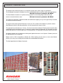
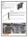
The Master wall formwork system is a complete system with a wide range of application.
The Alu Master formwork is suitable for minor, manhandled tasks as well as large area applications.
Allowed concrete pressure 60 KN/m²
The Steel Master formwork is a perfect strong system for concreting large areas at one go
and to be moved with the crane
Allowed concrete pressure 80 KN/m²
The panel-size grid with 10 different width and 4 different heights gives you the opportunity to master
all construction site situations.
The panel frames have profile thickness of 123 mm. The surface of Alu Master is powder coated,
Steel Master surface is hot-dip galvanized. All the elements are easy to clean.
The plywood has a thickness of 18 mm. You have the choice between Finnish plywood (both sides
coated with reinforced phenolic resin, 13 layers) or plastic coated red plywood (1,8 mm plastic on both
sides) that lasts up to 3 times longer than Finnish plywood. The plywood is fixed by rivets and screws.
Alu Master panels can be transported with special pallets that save a lot of space. Smaller parts can
be transported in Uni containers.
Master steel is 100% compatible to Master Alu. While waiting for the crane to move steel Master
panels, you can go on erecting the formwork with manhandled Alu Master.
The ideal application for Master formwork:
straight walls
circular walls
columns
4
II) The handling of Master formwork:
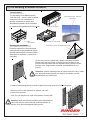
Transportation:
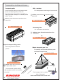
The unloading of Alu Master panels
from the truck can be done in pallets,
accessories in Uni containers or
special containers for small parts.
Steel Master panels can be unloaded
in staples and separated with lifting chain.
crane transport wtih STAPOS
lifting chain
Pallet for Alu panels
container for accessories
Uni container
Erecting the formwork:
separating of panels by Master lifting chain
Remove bracket from the pallet and
spray panels and plywood with Ringer
special release agent (it makes easier
afterwards to separate panels from
concrete).
At the site connect panels with Master one hand couplers.
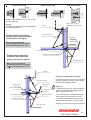
Clamp push and pull props to the panels and fix them to the
ground. Now the panels can be alligned exactly. With the crane
you can erect large blocks of panels, preassembled on the
ground.
Attention: before releasing block of panels from the crane, make
sure that push and pull props are fixed to the panels to avoid
destabilization by wind forces.
Continue assembling panels or block of panels this way and connect them together.
When one side of the formwork is erected, you can
install reinforcement.
Then you can thread in tie rods in the panels of outer side.
Attention: Multi panel blocks should not be released from
crane until they are anchored with sufficient amount of
anchors, thus protected against falling down.
5
Concreting:
Alu Master panels have an allowed max. concrete pressure of
60 kN/m².
Steel Master panels have an allowed max concrete pressure
80 kN/m².
See DIN 18218.
Usage of concrete compactor must comply with DIN 4235.
Pay attention to the climb rate of concrete.
After concreting clean the back side of the panels
with water immediately.
Dismantling:
When concrete is freshly hardened , you can begin the dismantling.
Release combi-plates, remove tie rods. Remove Master one hand
couplers and bear away the panels.
Clean residual concrete off the panels and spray special release
agent.
When dismantling with crane , you can lift the whole multi panel
block with push and pull props and concreting or 3S platforms.
Attention: Don´t breake apart multi panel blocks with crane
6
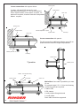
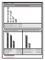
III) Description of system parts:
Panels:
Alu Master Panel:
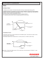
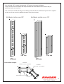
Alu Master panel consists of dimensionally stable and warp resistant hollow frame profile.
Alu Master panels have an allowed max. concrete pressure of 60 kN/m² (DIN 18218). Diagonal stiffener
stabilizes the profile and prevents deformation or torsion. There is a stable area on the profile for
fastening couplers, stabilized by diagonal stiffener
The frame profile protects plywood and serves for its edge protection.
Two supporting areas make it easier to separate panels from each other.
supporting area
edge protection
Alu-Master
frame profile
supporting area for
plywood
diagonal stiffener
area for fastening
coupler
Steel Master Panel:
Steel Master panel has only little deviations from Alu Master panel. The profiles are made of rolled
sectioned of grain refined steel.
Steel Master panels have an allowed max. concrete pressure of 80 kN/m² (DIN 18218).
supporting area
edge protection
Steel-Master
frame profile
supporting area for
plywood
area for fastening
coupler
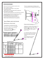
Advice: When Steel Master panels 135 cm width have concrete pressure of 80kN/m², tie rods
DW 20 should be used!
7
frame profile
31
23
30
122
38
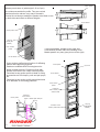
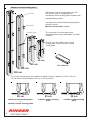
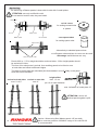
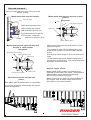
Master panels have 4 (with height 3,30 m 6 pcs)
tie rod sleeves welded in profile. They are conical
and therefore tie rods are very easy to thread in.
Conical tie rod sleeves enable the panels to be tilted on one
or both sides and offset to different heights.
31
23
47
frame profile
39
tie rod sleeve
carrying
handle (Alu
Master)
cross section
4 carrying handles, welded on the edge and
cross section profiles make the handling of Alu
Master panels very easy (see picture to the right)
profile
tie rod sleeve
Cross section profiles have function of stiffening
frames and supporting plywood.
Panels are available with Finnish plywood or
plastic coated plywood. Plywood is fixed with
screws and rivets to the cross section profiles.
Functional cross section profile is ideal for fixing
accessories as RS clamps, push and pull props,
etc.
Functional cross section profile has drilled holes
to fix brackets of concreting platforms.
frame profie
plywood
tie rod sleeve
cross section
profile
functional
cross section profile
without holes
frame profile
functional
cross section
profile Master push and pull
prop
carrying
functional cross
section profile with hole
8
handle (Steel
Master)
System grid:
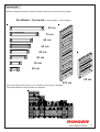
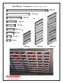
With the widths and heights of different Master panels you can shutter any shape.
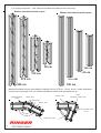
Alu-Master - formwork: 8 panel widths , 2 panel heights
90 cm
75 cm
60 cm
55 cm
50 cm
45 cm
30 cm
25 cm
270 cm
90 cm
Due to the ideal system grid you can combine panels lying or standing.
That makes Master system flexible and adaptive.
9
Steel Master - formwork: 9 panel width, 3 panel heights
240 cm
135 cm
90 cm
60 cm
55 cm
50 cm
45 cm
30 cm
25 cm
135 cm
10
270 cm
330 cm
Master multi purpose panels:
Suitable for casting columns, corners, wall connections
and stop ends.
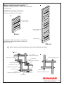
Alu Master multi purpose panels:
There are 2 heights in 75 cm width:
functional profile
with 5 cm grid
functional profile
with 5 cm grid
90 cm
connecting tube
5 cm pattern makes it possible to cast different
wall thickness and cross sections of columns
from 20 to 60 cm
270 cm
Advice: please close holes that are not in use with brown tie cones
panel Master
Master
multi purpose fixing bolt
wall thickness 25 cm
Master multi purpose panel
spacer tube
Master one hand coupler
Master inside corner
wall thickness: 20 cm
Master multi purpose panel
combi plate
combi plate
Master multi purpose fixing bolt
Master multi purpose fixing bolt
wall thickness: 30 cm
panel Master
11
Steel Master multi purpose panel
There are 3 heights in width 90 cm of Steel Master multi
purpose panels available.
It is recommended to use crane to move Steel
Master multi purpose panels.
functional profile
with 5 cm grid
functional profile
with 5 cm grid
135 cm
connecting tube
5 cm pattern makes it possible to cast different
wall thickness and cross sections of columns
from 20 to 75 cm
You need only Master multi purpose fixing bolts
and combi plates to connect panels.
Master multi purpose fixing bolt
combi plate
12
270 cm
330 cm
Master corners:
90° corners can be built up with Alu/Steel Master inside and outside corners that are available in
the following heights:
Alu Master inside corner
Steel Master inside corner
Master outside corner
90 cm
90 cm
270 cm
135 cm
330 cm
Master panel
270 cm
Master outside
corner
Master panel
135 cm
270 cm
330 cm
Alu Master inside corners have leg length of
25 cm and 30 cm (length 30 cm with
plywood). Steel Master inside corners have
leg length 30cm. On the left picture the
usage of outside corner with corresponding
wall thickness is shown.
Master inside corner
25 cm side length
wall thickness: 25 cm
13
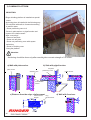
For varying corners 60° - 180° inside and outside articulated corners are used.
Master articulated inside corner
Master articulated outside corner
90 cm
90 cm
135 cm
135 cm
270 cm
270 cm
330 cm
330 cm
Master articulated corners are available in heights 330 cm, 270 cm, 135 cm, 90 cm. Inside articulated
corners have leg length of 30 cm; outside articulated corners have leg length of 6 cm.
adjustable Master
Master -waler
Master panel
Master
articulated outside corner
coupler
square timber
Master waler
m
0°
.6
in
m ax
. 18 0
°
Master RS - clamp
14
Master articulated inside
corner
You can build 135° corners using special 135°corners in system Alu Master.
These corners are more stable and wrap resistant then articulated corners, that is why no
additional walers are required.
135° corners are made that way, when casting a wall with 25 cm thickness they are fixed together
so that you do not need any additional panels (see picture below).
Alu-Master inside corner135°
Alu-Master outside corner 135°
135 cm
270 cm
135 cm
270 cm
connection sample:
Alu-Master outside corner 135° 270/30/30
Alu-Master inside corner 135° 270/20/20
wall thickness: 25 cm
135
°
15
Master circular forming plate:
With Master circular forming plates you can
cast circular walls in a polygonal way.
Use Master circular forming plates together with
standard Master panels.
crane hook
You will get the required radius by adjusting the
prestress device.
Minimum inside radius: 1,80 m
fixing device
The connection of circular panels with
standard panels is made with Master one hand
couplers.
prestress device
Fit in tie rod in the middle of the circular
forming plate, fix with Uni waler 40 and
combi plates.
90 cm
135 cm
Uni waler 40
270 cm
330 cm
The circular forming plates are available for Master system in heights of 330 cm, 270 cm,
135 cm and 90 cm and widths of 20 cm, 25 cm and 30 cm.
20 cm
25 cm
30 cm
Inside circular forming plate
outside circular forming
plate
outside circular forming
plate
or
outside circular forming plate
16
Example:
Circular waste water tank: inside radius: 3,50 m
wall thickness: 0,25 m
Master panels 270/45:
are used for inside as well as outside
Master circular forming
plate 20: standard circular
formimg plate for inside
formwork
Master one hand coupler
Uni waler 40
Master circular forming
plate 25:
standard - circular
forming plate
for outside formwork
Simplified drawing without tie rods
and push and pull props
Master circular forming plate 20:
for lenght adjustment distributed evenly
around the circumference.
combi palte
Uni waler 40
Master circular forming plate 270/20
Master panel 270/45
tie rod
Master one hand coupler
17
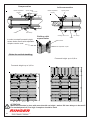
Radius segment diagram:
Panel width
5
135
W andstärke = <_ 20 cm
Kreisbogenabweichung [cm]
4
3
W an dstärke =
90
<_ 15
cm
2
60
45
1
30
0
0
2
4
6
8
10
12
14
16
18
Inner radius (m)
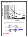
This radius segment diagram is to determine maximal panel width and permitted deviations
.
from circular arc.
18
20
Calculation of the best distribution of
panels:
Example:
Data
Inside radius: 450 cm
Outside radius: 475 cm
Length of concreting section :
943 cm
(1/3 of inside perimeter)
Inside radius [cm]
Outside radius [cm]
Length of concreting section [cm]
Choice of panel width [cm]
Check permitted segment dimensions
Panel width selected :
in the radius segment diagram.
60 cm
For inside formwork
Take circular forming plate 20 cm
Quantity of panels calculation
(length of concreting section - panel width)
(panel width + 20)
......
=
The result is the quantity of Master circular
forming plates required for one side of formwork.
The quantity of standard panels should be 1 piece
more then quantity of circular forming plates.
(943 - 60)
(60 + 20)
= 11
Quantity circular forming plates: 11
Quantity standard panels: 12
Determining of the distribution of Master circular
forming plates for outside formwork:
outside radius x (panel width + 20) - panel width = ....
inner radius
The next smaller Master circular forming plate
is selected as „Type 1“
Insert the difference in the formula below and you
get the number of Master circular forming
plates "Type 1".
qty of circular forming plates x (1-
difference ) = qty "Type 1"
5
By subtracting the quantity of "Type 1" from the
selected quantity of circular forming plates, you
get the number of circular forming plates"Type 2".
475
450
x (60 + 20) - 60 = 24,44 cm
Circular forming plate "Type 1" = 20 cm
Difference = 4,44 cm
4,44
= 11 x (1- 5
) = 1,23
2 circular forming plates "Type 1" (20 cm)
9 circular forming plates "Type 2" (25 cm)
"Type 2" is the next larger circular forming plate
19
Master wall thickness compensation:
330/10
270/10
This is the best alternative to fitting timber compensations. For compensation up to
5 cm only 2 adjustable couplers and no other additional parts are required. For
compensations from 5,1 cm, 2 adjustable couplers, 3 Master
walers 100 with 6 RS clamps are required.
wall thickness compensation
10cm
sizes:
Wall thickness compensation 330/10
Wall thickness compensation 330/5
Wall thickness compensation 330/3
135/10
90/10
waler100
Wall thickness compensation 330/2
Wall thickness compensation 270/10
Wall thickness compensation 270/5
tie rod
Wall thickness compensation 270/3
Wall thickness compensation 270/2
Wall thickness compensation 135/10
Wall thickness compensation 135/5
combi plate
Wall thickness compensation 90/10
Master adjustable
coupler
Master dismantling device:
Master dismantling device is used to make the dismantling of lift shafts, staircases etc. easy and quick.
Availabe heights are 270 cm and 135 cm. It is fixed with 3 Master adjustable couplers, 3 walers 100.
waler
Master dismantling
device
After wignut counterplates are released,
both halves are separated and you
can dismantle easy.
wingnut counterplate
Master adjustable
coupler
20
Master Dismantling Corner
EASY SOLUTION FOR LIFT SHAFTS
Innovative solution for inside formwork of lift shafts
Due to the mechanism that is used in dismantling corner, formwork can be released from
concrete very quickly and it can be moved further in complete block.
Usage (shifting) is effected with help of:
Adjustable spindle
- adjustable spindle, whereas tie rod DW15
or ratch can be used
- crane, while lifting adjustable bar
Attention: Bolts of adjustable spindle must be removed! Bolt
Crane hook
Height extension:
For height extension of formwork, remove bolt from
adjustable spindle and use it as connecting bolt to fix
upper dismantling corner, when inserting this bolt
in the hole of adjustable spindle of the upper corner.
Height of dismantling corners:
Heights 1,35, 2,70 and 3,30 m are available,
max. height extension up to 5,4m is possible
Place for
anchoring
Advice: For connection use only UNI couplers!
Adjustable bar
21
Master connection devices:
Master panels are connected with Master one hand couplers. By panel height of 2,70 m
only 2 one hand couplers to connect the panels are required. For Master outside corner height
2,70 m 8 one hand couplers are used, i.e. 4 couplers for each side.
To connect Master panels 3,30 m height 3 one hand couplers are required and for outside
corner 3,30 m height 12 couplers are used.
Master one hand coupler is a self closing device that is why you can fix the coupler
using one hand only. With a single blow of hammer you create a fast, self
aligning and tension proof joint.
For compensation of distances up to max. 20 cm Master adjustable coupler is used.
The distance between two jaws of the coupler is changed by tie rod DW 15.
By panel height up to 2,70 m 2 pieces and by panel height 3,30 m 3 pieces of adjustable
couplers for length compensation or in-line connection are required.
Master truing adjustable clamp
For compensation of distances up to max 10 cm Master truing adjustable clamp can be used.
Advantage: Clamp also acts to align formwork panels.
By compensation of less than 5cm no walers are required.
By panel height up to 2,70 m 2 pieces and by panel height 3,30 m 3 pieces of truing adjustable
couplers for length compensation or in-line connection are required.
Advice: The coupler is to be fixed at cross section profile
22
Master waler:
For vertical stacking Master waler 150
for stiffening the block of panels should be used.
waler 150
Master waler 100 is used mainly for
compensation and in-line connection.
waler 100
functional profile
waler
RS - clamp
Fix walers with Master RS clamps to
functional profile. Per each waler 2
RS clamps are required.
Walers can also be fixed by anchors.
RS - clamp
If panels are assembled horizontally without square timber, a hexagon nut DW 15 + a
counter plate KL instead of a combi plate should be used.
without square timber
with square timber
RS - clamp
counter palte KL
hexagon nut DW 15
tie rod
square timber
waler 150
23
Anchoring:
The anchoring of Master panels is done with tie rods with 2 combi plates.
ATTENTION: use only certified tie rods!
Do not weld or heat tie rods, they can break!
combi plate
uni tie cones
for sealing unused holes
in panels.
tie rod
spacer tube
Master panel
tie rod sleeve
cone space tubes
for sealing spacer tube.
spacer tube
Alternatively to standard spacer tubes
cut off spacer tubes and two tie cones can be used.
Advantage: wall thickness can vary
cones for spacer tube
Panels 0,90 m - 2,70 m height should be anchored twice, 3,30 m height panels should
be anchored 3 times.
The form of tie rod sleeves is conical, thus enabling panels to be tilted on one
or both sides and offset to different heights.
The plate of combi plate has articulated joint that enables it to be fit solidly on the panel
even with some inclination.
conical on both sides conical on one side
max. 2 x 4,5°
max. 4°
height offset
max. 1,0 cm
per 10 cm wall thickness
max. inclination of combi plate 10°
ATTENTION: secure all
inclined panels against uplift
24
Advice: When using Steel Master panels 135 cm width
with a concrete pressure of 80kN/m² usage of tie rods DW 20
is recommended!
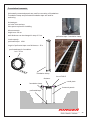
Foundation formwork
Horizontally connected panels are used for concreting of foundations.
Foundation clamp and perforated foundation tape are used for
anchoring.
Advantages:
no holes from anchors
little space required for installing
Measurements:
height max. 90 cm
wall thickness can be changed in step of 5 cm
perforated tape - foundation clamp
Load capacity:
perforated tape: 12kN
length of perforated tape =wall thickness + 50 cm
perforated tape for foundation
1 roll - 25 lm
foundation clamp
tie rod DW15
distance
foundation clamp
combi plate
formwork panels
perforated tape
25
tie rod
combi plate
If concreting height is the same as panel height
, anchor fixing angle should be used.
In case this anchor fixing angle is not used, the
upper concrete layer can be too thin with
standard anchoring.
anchor fixing angle
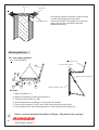
Working paltforms:
3S - concreting platform
max. load: 200 kg/m²
3S - platform 3,0 m
3S -concreting bracket
1
Master -push and pull prop
4
2
6
3
5
Master formwork panel
Montage:
1. Open 3S platform (1)
2. Remove connecting (2) and security bolt (3)
3. Tilt back vertical beam (4) (AB)
4. Fix horizontal beam (5) behind + in front and pull forwards.
5. Tilt up vertical beam(4) (AUF) and fix with connecting and security bolt.
6. Fix 3S platform with 3S concreting bracket to the formwork with bracket (6).
Please see more detailed information in Ringer „3S platform user manual“
26
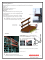
Concreting platform „L“
Concreting platform „L“is ready-to-use working platform of the following dimensions:
Length 2,7 m
Width 1,0 m.
Distance between brackets 1,86 m
Load capacity: 200 kg / m²
Mounting:
- Open guardrail and fix it with bolts and spring cotters
- Hang transportation gear at safety brackets and hooks
of the guardrail
guardrail
-Lift the platform and hang on frame profile of panels
- Take away transportation gear, lock safety brackets
ATTENTION: put H 20 beam 1,80 m length between
brackets when platform is placed o the ground
safety bracket
places for hanging
transportation gear
H20 beam
Brackets:
Master bracket consists of a bracket itself and
a hand rail post.
Width of the bracket is 75 cm
Max. distance between brackets: 1,5m
Max load: 200 kg/m²
You can fix brackets at horizontal or vertical panels.
Make sure that no lifting of the bracket is possible!
Fix side guards!
Advice: for safe use please follow all
corresponding regulations issued by local authorities.
27
Push and pull props:
There is a special place on Master panel
Master push and pull props are used to erect
functional profile for fixing push and pull props.
and to support formwork.
They make formwork stable in every phase
of construction work.
Please observe the applicable safety regulations,
pay attention to wind loads
All push and pull props have to be anchored in concrete
with guaranteed tensile and compression strength.
Anchoring loads: please see tables below.
For anchoring you can use for example,
compact concreting nail HKD M16 from Hilti.
Please follow the instructions of the producer.
Types of Master push and pull props.
Standard push and pull props.
Push and pull props type „ G“ :
The adjustment of push and pull prop
from 2,05 m to max. 3,55 m is possible ,
the maximum height of the formwork
should not exceed 4,50 m.
Adjustment of push and pull props „G“ is
possible from 3,50 m to max. 5,90 m.
With push and pull prop „G“ you can
reach the height of the formwork
up to. 6,70 m.
Quantity of push and pull props with
2,70m width block of panels
Formworkheight
push and
pull prop
3,60 m
4,80 m
5,40 m
In combination with the extension
part you can reach the formwork
height from 6,20 m up to max.
8,40 m.
If you need higher formwork,
please contact company
Ringer.
push and pull
pull prop "G"
1
1
1
1
permitted loads
push and pull
prop "G"
push and
pull prop
length
Compression
extended strength
(kN)
(m)
28
2,05
2,55
3,05
3,55
22
20
15
12
3,50
4,30
5,10
5,90
6,20
7,30
8,40
40
40
40
30
20
20
20
Tensile
strength
(kN)
Anchoring
load (kN)
18
12
40
24
Moving by crane:
Large blocks of panels are shifted with Master
crane hook.
Crane hook should be fixed at the profile of the panel in
the area of the joint or in the stiffened area.
You can do that by lifting c-clamp by hand.
ATTENTION: by lifting up the lying panels
adhere carefully the direction of load:
STRICKTLY UPRIGHT
max load: 12kN / crane hook
Before lifting formwork with a hook you have to control
that panel profile is placed completely in the recess of
the crane hook and that the bottom edge of c-clamp is on the
panel profile.
Otherwise there is a danger that formwork slips out of the hook.
ATTENTION:
The maximum load on the crane hook should not exceed 1200 kg!
Before usage check the hook for any visible damage or deformation.
Never pull the formwork with the crane from concrete, there is a danger of overloading the
crane hook.
Yearly inspection of crane hooks is to be made by authorized specialist.
Master crane hook is to be fixed in
the area of panel joint or stiffened area
to avoid slipping out.
Suspend block of panels
symmetrically (take care of centre of
gravity)
Maximum possible spread of
lifting tackle - 60°.
When a large block of panels is
mounted on the ground, use walers
150 to stiffen to avoid further buckling
of panels in the block.
Master crane hooks
waler 150
RS -clamp
Please follow the directions of
User Manual !
Master one hand coupler
29
Transportation, stacking and storage:
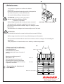
Formwork pallet
In one formwork pallet you can transport and
store 8 Alu Master panels 2,70x0,9 m
For transporting panels 0,90 m and 0,75 m
width you need 2 stirrups. For smaller panels
take 4 stirrups.
Advice: please follow the instruction of the
data sheet
max. load: 8,0 kN
‘
UNI - container
For transportation and storage of accessories
Advice: please follow the instruction of the
data sheet
max. load: 15 kN
Accessory box
For all formwork accessories
Advice: please follow the instruction of the
data sheet
max. load: 16 kN
Stapos transport lifting chain.
Safe transportation of Master
panels.
Master transport gear 3 m
For stacking and separating Master panels
use Master transport gear.
max. load: 16 kN
max.load : 20 kN
Advice: follow the instructions
of Stapos data sheet!
Secure panels against shifting
with transport cones. Use 2 pieces
per panel
Push transport bolt in outside
hole of the panel.
Under load transport bolt secures itself.
30
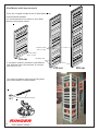
IV) Range of application:
Wall junctions, offsets:
waler 100
For T-junction with square timber with panel
height 2,70 - 3,3 m 3 walers 100 for each
side should be used.
To be able to use combi plates, take
care that minimum square timber
thickness is 3 cm.
Square timbers up to 5 cm width can be
used without walers.
hexagon nut DW 15
existing wall
sqare timber
RS clamp
counter plate KL
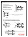
For T-junction without square timber
counter plate KL + hexagon nut DW 15
should to be used
existing wall
In-line connections can be made with Master panels or square timber.
For panel height 2,70 - 3,3 m 3 walers and 6 RS clamps should be used.
To fix square timber additionally 2 adjustable Master couplers are required.
existing wall
Master adjustable
square timber
RS clamp
coupler
Master panel
existing wall
existing wall
Master multi purpose panel
With Master multi purpose panels inline connections are also possible
31
existing wall
Corner connection with square timber:
3 walers 100 and 6 RS clamps for each
side with panel height 2,70 - 3,3 m are required.
square timber
waler 100
When square timber is less than 5 cm thick, no
walers are required, it can be fixed with 2 adjustable
Master couplers
existing wall
Master-adjustable coupler
square timber
square timber
RS clamp
waler 100
Corner connection with panels:
For this connection additionally Master panel 25 cm
width should be used for length compensation.
Master panel 25 cm width
RS clamp
inside corner
T- junction
Master panel
Master multi purpose fixing
bolt
square timber
combi plate
waler 100
Wall offset of one side is possible up to max.
12 cm.
For panels height 2,70 - 3,30 m the following
connecting parts are required:
3 walers 100,
3 RS clamps,
3 multi purpose fixing bolts and
3 combi plates.
Short walls should be supported.
32
Stop-end formwork
There are many options to form a stop-end with
Master system.
Master panel with stop-end coupler
Master panel with stop-end anchors or multi
purpose
stop-end coupler
fixing bolts.
waler 100
multi purpose fixing bolt
Quick and convenient way
without using any anchors
combi plate
(wall thickness up to 40 cm)
3 stop-end anchors for panels
2,70 m height, 4 stop-end
anchors for panels 3,30 m
height
Master stop-end anchor
Master multi purpose panel with stop-end
anchors or multi purpose
fixing bolts.
Master multi purpose panel
Master stop end anchor
Master panel
Waler can be fixed with stop-end anchor or multi
purpose fixing bolt.
They should be fixed in the middle between two
cross section profiles, so that the load is spread
evenly.
Stop-ends of panels height 2,70 m are anchored 3
times
( 6 stop-end anchors/multi purpose fixing bolts, 3
walers and 6 combi plates). 3,30 m high stop-ends
should be anchored 4 times.
Stepless height offsets.
Master panel
multi purpose fixing bolt
Areas that cannot be reached with
panels:
With walers and RS clamps there is a possibility
Master panel profile enables connections to be
fastened on each side of the frame. Thus panels of
different sizes can be connected steplessly,
without being confined to any grid.
Master formwork can easily be accommodated to
any shapes such as steps, slopes and uneven
floors with no extra cost and time.
to cover the remaining areas simply with square
timber and plywood.
33
Compensation
Master adjustable
In-line connection
square timber
Master adjustable
coupler
max. 20 cm
coupler
waler
square timber
RS - clamp
In order to extend formwork height,
square timber fixed it with adjustable
couplers can be used.
existing wall: 25 cm
Build-up with
square timber
RS - clamp
waler
square timber
Master adjustable coupler
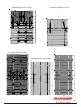
Rules for vertical stocking:
Formwork height: up to 3,60 m
270
270
30
bis 90
Formwork height: up to 3,00 m
90
B i
90
Ei
t
90
90
B t
i büh
90
90
h
ATTENTION:
When the extension is done with more than 90 cm height , walers 150 have always to be used!!
For stocked panels 2,70 m high 3 couplers should be used
34
Formwork height: up to 4,05 m
270
270
135
90
75
Formwork height: up to 4,80 m
240
Formwork height: up to 5,40 m
30
Formwork height: up to 5,40 m
240,0
270
270
240,0
270
270
Formwork height: up to 4,80 m
90
90
90
270
240
35
Climbing formwork:
For climbing (installing formwork on platforms) can 3S platform and special climbing platform
be used.
More details you can find in 3 S platform and climbing platform User
Manuals
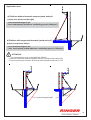
1) 3 S platform
Mounting:
1. Attach nail plate with nails to the formwork plywood.
Distance to the top edge (ceiling) should be 6,0 cm + height of wooden platform
Platform should be flush with top edge of ceiling (see picture page S. 37)
2. Unscrew anchor sleeve:
Attention: anchor sleeve DW20, ALU L = 28 cm should be fixed with concrete
reinforcement in right position!
Anchor sleeve DW 20, V2A L = 17 cm with a movable part should be pushed through
concrete reinforcement and fixed it in the right position!
3. Concrete.
4. Remove end shutter.
5. Screw out nailing plate with key (SW 24) .
6. Mount adaptor for climbing platform (SW 36)
7. When concrete is hardened (necessary concrete strength 10N/mm²), fix 3S platform
with brackets.
36
Anchoring in wall
Anchoring in slab
detail - ceiling
2 anchors in wall
15,0
5 10 cm
Usage of 3S platforms 2,5 m, 3,0 m and
corner platforms.
Fixing:
Fixation with anchor sleeves and adaptor
for climbing platform
Platform without formwork
support (push and pull props)
(see picture to the right)
are to be fixed in
distance of 15,0 cm
bracket
push and pull prop
3S platform
square timber
Max. load according to
scaffolding group 3 200 kg/m²
Formwork height up to 5,4 m
anchor screw DW 20
anchor sleeve DW 20
Platform with supported
formwork (push and pull
props) (see picture below)
3S adaptor for climbing platform
3S shifting bracket
Max. load according to
scaffolding group 2 150 kg/m²
Formwork height up to 2,7 m
bracket
Fixation of push and pull props
push and pull prop
square timber
3S platform
anchor screw DW 20
push and pull prop screw
anchor sleeve DW 20
3S shifting bracket
3S adaptor for climbing
Push and pull props are to be fixed with
special screws for push and pull props
by each 3S shifting bracket.
Attention
- Platforms have to be secured against
uplift, for example with safety devices
(belt ) against the wind!
-You are allowed to use platforms with
wind speed not more than 50 km/h
- Formwork with platforms have to be
additionally supported in case of long
breaks in construction, high wind speed
wind safety belt
37
2) CLIMBING PLATFORM
MOUNTING:
Ringer climbing platform is installed on special
cones.
Anchoring place is installed in the following way
-Fix nail plate with nails to formwork according
to anchor raster
- Screw positioning cone to it
-Screw in plate anchor or pigtail anchor and
connect it to reinforcement
After concreting!!
- Remove formwork
- Screw out nail plate
- Screw out positioning cone with square
socket key
- Screw in climbing cone
- Hang the platform
Attention:
Anchoring should be done only after reaching the concrete strength of 10 N/mm²
a) Wall with plate anchor
b) Slab with pigtail anchor
nail plate
plate anchor
climbing cone
positioning cone
pigtail anchor
reinforcement
bracket
c) Distance from the edge, reinforcement
reinforcement
bracket
38
long
reinforcement
d) Wall with 2 anchors
Application area:
a) Platform without formwork support (push and pull
props) (see picture to the right)
- max. formwork height: 5,4m
- max. load capacity of platform: scaffolding group 3 (200 kg/m²)
b) Platform with supported formwork (push and pull
props) (see picture below)
- max. formwork height: 3,3m
- max. load capacity of both platforms: scaffolding group 2 (150 kg/m²)
ATTENTION:
- Max. wind speed (to work on the platform): 50km/h
- Platforms should be protected against uplift (for example with safety belt)
- Push and pull props should to be fixed at each bracket at interval of 1,5m
protection agaist uplift
39
Single sided wall formwork
Brace frames (Supporting construction frames) „S“ and „L“ for single sided wall formwork up to 6 m height.
Please find detailed instructions in user information for Brace Frames.
40
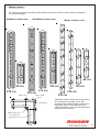
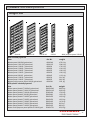
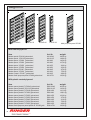
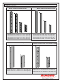
V) PANELS: Steel Master galvanized
Height 330
330/240
330/135
330/45-90
330/30
Multi purpose panel 330/90
With finnish plywood
item
Art. Nr.
weight
Master panel 330/240 galvanized
Master panel 330/135 galvanized
Master panel 330/90 galvanized
Master panel 330/60 galvanized
Master panel 330/55 galvanized
Master panel 330/50 galvanized
Master panel 330/45 galvanized
Master panel 330/30 galvanized
Master panel 330/25 galvanized
Master multi purpose panel 330/90 galvanized
805V240
805V135
805V90
805V60
805V55
805V50
805V45
805V30
805V25
805V901
470,0 kg
238,0 kg
174,0 kg
133,0 kg
126,0 kg
120,0 kg
112,0 kg
92,0 kg
88,0 kg
202, kg
With plastic coated plywood
item
Art. Nr.
weight
Master panel plastic E 330/240 galvanized
Master panel plastic E 330/135 galvanized
Master panel plastic E 330/90 galvanized
Master panel plasticE 330/60 galvanized
Master panel plastic E 330/55 galvanized
Master panel plastic E 330/50 galvanized
Master panel plastic E 330/45 galvanized
Master panel plastic E 330/30 galvanized
Master panel plastic E 330/25 galvanized
Master multi purpose panel plasticE 330/90 galv.
E805V240
E805V135
E805V90
E805V60
E805V55
E805V50
E805V45
E805V30
E805V25
E805V751
486,0 kg
238,0 kg
174,0 kg
133,0 kg
126,0 kg
120,0 kg
112,0 kg
92,0 kg
88,0 kg
202,0 kg
41
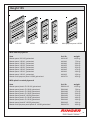
Height 270
270/240
270/135
270/45-90
270/25-30
Multi purpose panel 270/90
With finnish plywood
item
Art. Nr.
weight
Master panel 270/240 galvanized
Master panel 270/135 galvanized
Master panel 270/90 galvanized
Master panel 270/60 galvanized
Master panel 270/55 galvanized
Master panel 270/50 galvanized
Master panel 270/45 galvanized
Master panel 270/30 galvanized
Master -panel 270/25 galvanized
Master multi purpose panel 270/90 galvanized
801V240
801V135
801V90
801V60
801V55
801V50
801V45
801V30
801V25
801V751
385,0 kg
188,0 kg
140,0 kg
107,0 kg
99,0 kg
92,0 kg
87,0 kg
75,0 kg
68,0 kg
162,0 kg
item
Art. Nr.
weight
Master panel plastic E 270/240 galvanized
Master panel plasticE 270/135 galvanized
Master panel plastic E 270/90 galvanized
Master panel plastic E 270/60 galvanized
Master panel plastic E 270/55 galvanized
Master panel plastic E 270/50 galvanized
Master panel plastic E 270/45 galvanized
Master panel plastic E 270/30 galvanized
Master panel plastic E 270/25 galvanized
Master multi purpose panel plastic E 270/90 galv.
E801V240
E801V135
E801V90
E801V60
E801V55
E801V50
E801V45
E801V30
E801V25
E801V751
402,0 kg
193,0 kg
141,0 kg
108,0 kg
103,0 kg
97,0 kg
91,0 kg
76,0 kg
69,0 kg
163,0 kg
With plastic coated plywood
42
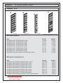
Height 135
135/135
135/90
135/45-60
135/25-30
Multi purpose panel 135/90
With finnish plywood
item
Art. Nr.
weight
Master panel 135/135 galvanized
Master panel 135/90 galvanized
Master panel 135/60 galvanized
Master panel 135/55 galvanized
Master panel 135/50 galvanized
Master panel 135/45 galvanized
Master panel 135/30 galvanized
Master panel 135/25 galvanized
Master multi purpose panel 135/90 galvanized
802V135
802V90
802V60
802V55
802V50
802V45
802V30
802V25
802V751
100,0 kg
77;0 kg
59,0 kg
52,0 kg
50,0 kg
47,0 kg
38,0 kg
35,0 kg
85,0 kg
item
Art. Nr.
weight
Master panel plastic E 135/135 galvanized
Master panel plastic E 135/90 galvanized
Master panel plastic E 135/60 galvanized
Master panel plastic E 135/55 galvanized
Master panel plasticE 135/50 galvanized
Master panel plastic E 135/45 galvanized
Master panel plastic E 135/30 galvanized
Master panel plasticE 135/25 galvanized
Master multi purpose panel plastic E 135/90 galvanized
E802V135
E802V90
E802V60
E802V55
E802V50
E802V45
E802V30
E802V25
E802V751
102,0 kg
75;0 kg
57,0 kg
54,0 kg
51,0 kg
48,0 kg
39,0 kg
36,0 kg
86,0 kg
With plastic coated plywood
43
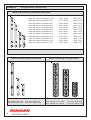
PANELS:
Alu-Master powder coated
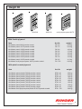
Height 270
270/90
270/45-75
270/25-30
multi purpose panel 270/75
With finnish plywood
item
Art. Nr.
Alu-Master panel 270/90N powder coated
Alu-Master panel 270/75 powder coated
Alu-Master panel 270/60 powder coated
Alu-Master panel 270/55 powder coated
Alu-Master panel 270/50 powder coated
Alu-Master panel 270/45 powder coated
Alu-Master panel 270/30 powder coated
Alu-Master panel 270/25 powder coated
Alu-Master multi purpose panel t 270/75 powder coated
701N90
701 90
701 60
701 55
701 50
701 45
701 30
701 25
701 751
weight
64,0 kg
55,0 kg
47,0 kg
44,0 kg
41,0 kg
38,0 kg
30,0 kg
27,0 kg
59,0 kg
With plastic coated plywood
44
item
Art. Nr.
Alu-Master panel plastic E 270/90N powder coated
Alu-Master panel plastic E 270/75 powder coated
Alu-Master panel plastic E 270/60 powder coated
Alu-Master panel plastic E 270/55 powder coated
Alu-Master panel plastic E 270/50 powder coated
Alu-Master panel plastic E 270/45 powder coated
Alu-Master panel plastic E 270/30 powder coated
Alu-Master panel plastic E 270/25 powder coated
Alu-Master multi purpose panel plast. E 270/75 powder coated
E701N90
E701 75
E701 60
E701 55
E701 50
E701 45
E701 30
E701 25
E701 751
weight
67,0 kg
58,0 kg
49,0 kg
46,0 kg
44,0 kg
41,0 kg
32,0 kg
29,0 kg
59,0 kg
Height 90
90/90
90/45-60
90/25-30
multi purpose panel 90/75
With finnish plywood
item
Art. Nr.
Alu-Master panel 90/90 powder coated
Alu-Master panel 90/75 powder coated
Alu-Master panel 90/60 powder coated
Alu-Master panel 90/55 powder coated
Alu-Master panel 90/50 powder coated
Alu-Master panel 90/45 powder coated
Alu-Master panel 90/30 powder coated
Alu-Master panel 90/25 powder coated
Alu-Master multi purpose panel 90/75 powder coated
702
702
702
702
702
702
702
702
701
weight
90
75
60
55
50
45
30
25
752
25,0 kg
22,0 kg
18,0 kg
17,0 kg
16,0 kg
15,0 kg
12,0 kg
11,0 kg
24,0 kg
item
Art. Nr.
weight
Alu-Master panel plastic E 90/90 powder coated
Alu-Master panel plastic E 90/75 powder coated
Alu-Master panel plastic E 90/60 powder coated
Alu-Master panel plastic E 90/55 powder coated
Alu-Master panel plastic E 90/50 powder coated
Alu-Master panel plastic E 90/45 powder coated
Alu-Master panel plastic E 90/30 powder coated
Alu-Master panel plastic E 90/25 powder coated
Alu-Master multi purpose panel plastic E 90/75 powder coated
E702
E702
E702
E702
E702
E702
E702
E702
E701
With plastic coated plywood
90
75
60
55
50
45
30
25
752
25,0 kg
22,0 kg
18,0 kg
17,0 kg
16,0 kg
15,0 kg
12,0 kg
11,0 kg
24,0 kg
45
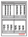
PANELS:
Corners
Master - outside corners galvanized
Master outside corner 330 galvanized Art.- Nr.: 703V132
weight: 48,0 kg
Master outside corner 270 galvanized Art.- Nr.: 703V13
weight:: 39,0 kg
Master outside corner 135 galvanized Art.- Nr.: 703V131
weight:: 20,0 kg
Master outside corner 90 galvanized Art.- Nr.: 703V16
weight:: 12,8 kg
Master inside corner galvanized
46
Master insidecorner330/30/30galv.withplywood
Art.-Nr.: 803V51 weight 128 kg
Master i nside corner 270/30/30 galv. with plywood
Art.-Nr.: 803V1811 weight 102 kg
Master i nside corner 135/30/30 galv. with plywood
Art.-Nr.: 803V1221 weight 53 kg
Master i nside corner 270/25/25
Art.-Nr.: 803 11 weight 110 kg
Master i nside corner 135/25/25
Art.-Nr.: 703V111 weight 55 kg
Alu-Master inside corner powder coated
Alu-Master inside corner 270/25/25 powder coated
Art.-Nr.: 703B11 weight 41 kg
Alu-Master -inside corner powder coated with plywood 270/30/30
Art.-Nr.: 703B212S weight 46 kg
Alu-Master inside corner 90/25/25 powder coated
Art.-Nr.: 703B12 weight 16 kg
Alu-Master inside corner powder coated with plywood 90/30/30
Art.-Nr.: 703B213S weight 16 kg
Panels: Corners
Master inside articulated corners
Master outside articulated corners
Master articulated corner I 330/30/30 Art.-Nr.: 703 014 weight: 155kg
Master articulated corner A 330/6/6 Art.-Nr. 703 0141 weight: 70kg
Master articulated corner I 270/30/30 Art.-Nr.: 703 14 weight: 110kg
Master articulated corner A 270/6/6 Art.-Nr. 703 141 weight: 51kg
Master articulated corner I 135/30/30 Art.-Nr.: 803 24 weight: 54 kg
Master articulated corner A 135/6/6 Art.-Nr.:803 241 weight: 26kg
Master articulated corner I 90/30/30 Art.-Nr.: 703 24 weight: 32 kg
Master -articulated corner A 90/6/6 Art.-Nr. 703 241 weight: 20kg
Alu Master outside corner135° powder coated Alu Master inside corner 135° powder coated
Alu-Master outside corner 135° 270/30/30 Art.-Nr.: 703B 19 weight: 40,0 kg
Alu-Master inside corner 135° 270/20/20 Art.-Nr.: 703 18 weight: 40 kg
Alu-Master outside corner 135° 135/30/30 Art.-Nr.: 703B192 weight:20,5 kg
Alu-Master inside cormer 135° 135/20/20 Art.-Nr.: 703 181weight: 14 kg
47
PANELS:
Compensation, dismantling
Master wall thickness compensation galvanized
Master wall thickness compensation 330/10
Art.-Nr. 704V821
weight: 20,0 kg
Master wall thickness compensation 330/5
Art.-Nr. 704V811
weight: 17,0 kg
Master wall thickness compensation 330/3
Art.-Nr. 704V871
weight: 14,5 kg
Master wall thickness compensation 330/2
Art.-Nr. 704V881
weight: 13,0 kg
Master wall thickness compensation 270/10
Art.-Nr. 704V82
weight: 16,5 kg
Master wall thickness compensation 270/5
Art.-Nr. 704V81
weight: 14,0 kg
Master wall thickness compensation 270/3
Art.-Nr. 704V87
weight: 11,2 kg
Master wall thickness compensation 270/2
Art.-Nr. 704V88
weight: 10,5 kg
Master wall thickness compensation 135/10
Art.-Nr. 704V84
weight: 8,5 kg
Master wall thickness compensation 135/5
Art.-Nr. 704V83
weight: 7,5 kg
Master wall thickness compensation 90/10
Art.-Nr. 704V86
weight: 5,5 kg
Master wall thickness compensation 90/5
Art.-Nr. 704V85
weight: 5,0 kg
Master dismantling device galvanized
Master dismantling corner galvanized
Master dismantling device 270/10 Art.-Nr. 704V9 weight: 49,5 kg
Master -dismantling corner 330/30/30
Art.-Nr. 706V3 weight: 251 kg
Master dismantling device 135/10
Master dismantling device 90/10
Master - dismantling corner 270/30/30
Art.-Nr. 706V2 weight: 202 kg
Master - dismantling corner 135/30/30
Art.-Nr. 706V1 weight: 107 kg
48
Art.-Nr. 704V10 weight: 26,0 kg
Art.-Nr. 704V11 weight: 18,0 kg
ELEMENTS:
Circular forming plates
Master circular forming pate 330 galvanzed
Master - Bogenblech 330/30 verzinkt
Master - Bogenblech 330/25 verzinkt
Master - Bogenblech 330/20 verzinkt
Master circular forming pate 270 galvanzed
Art.-Nr.: 903 30 Gewicht: 89 kg
Master circular forming plate 270/30
Art.-Nr.: 903 25 Gewicht: 87,5kg Master circular forming plate 270/25
Art.-Nr.: 903 20 Gewicht: 86 kg Master circular forming plate 270/20
Master circular forming pate 135 galvanzed
Art.-Nr.: 703V23 weight: 66 kg
Art.-Nr.: 703V22 weight:: 63 kg
Art.-Nr.: 703V20 weight: 60 kg
Master circular forming pate 90 galvanzed
Master circular forming plate 135/30
Art.-Nr.: 803V221 weight:34 kg
Master circular forming plate 90/30
Art.-Nr.: 703V231 weight: 25 kg
Master circular forming plate 135/25
Art.-Nr.: 803V211 weight: 32 kg
Master circular forming plate 90/25
Art.-Nr.: 703V221 weight: 23 kg
Art.-Nr.: 803V201 weight: 31 kg
Master circular forming plate 90/20
Art.-Nr.: 703V201 weight: 22 kg
Master circular forming plateh 135/20
49
ACCESSORIES:
foundation clamp
galvanized
stop end coupler
galvanized
guard rail clamp
0 - 0,60 m galvanized
weight: 6,5 kg
Art.- Nr.: 703V154
weight: : 8,3 kg
Art.- Nr.: 704V69
weight: : 9,5 kg
Art.- Nr.: 230V6
Master anchor fixing angle
galvanized
Master concrete fill-in help
Master stop end anchor
galvanized
L = 40 cm
weight: : 1,75 kg
Art.- Nr.: 407V61
50
weight: 2,7 kg
Art.- Nr.: B561
weight : 1,5 kg
Art.- Nr.: 704V68
ACCESSORIES:
Master one hand coupler
galvanized
Master adjustable
coupler galvanized
Combi plate
galvanized
weight 3,4 kg
Art.- Nr.: 704V6
weight 4,7 kg
Art.- Nr.: 704V61
weight 1,0 kg
Art.- Nr.: 407V77
Tie rod DW15 1,00 m
galvanized
(other sizes available)
Master multi purpose fixing
bolt galvanized
Master adjustable trueing
coupler galvanized
L = 30 cm
weight : 1,5 kg
Art.- Nr.: 407 100
weight : 0,6 kg
Art.- Nr.: 705V1
Counter plate
120x120x8 mm galvanized
Wingnut counter plate
galvanized
Wingnut
galvanized
weight : 0,9 kg
Art.- Nr.: 407V73
weight 0,6 kg
Art.- Nr.: 407V75
weight : 0,3 kg
Art.- Nr.: 407V71
weight : 5,6 kg
Art.- Nr.: 704V72
51
ACCESSORIES
Hexagon coupler
DW15 galvanized
Counter plate KL
galvanized
Rock anchor
34-35mm
weight: 0,2 kg
Art.- Nr.: 407V8
weight: 0,29 kg
Art.- Nr.: 404V52
weight: 0,37 kg
Art.- Nr.: 407 60
UNI - container with flap
galvanized
Pallet for Alu formwork
galvanized
Accessory box
galvanized
+ stirrup for pallet galvanized
weight 4,2 kg
Art.- Nr.: 408V91
weight: 72,0 kg
Art.- Nr.: 260V10
UNI - container
without flap galvanized
weight : 70 kg
Art.- Nr.: 260V11
52
weight 80,0 kg
Art.- Nr.: 408V90
weight: 160,0 kg
Art.- Nr.: 260V0006
Master lifting device
with 4 chains 3m
Master stacking cones
for panels
weight: 15,0 kg
Art.- Nr.: 708 41
weight: 0,2 kg
Art.- Nr.: 708 421
ACCESSORIES:
Waler 100(90)
galvanized
Waler 150
galvanized
RS clamp
galvanized
weight: 12,8 kg
Art.- Nr.: 703V151
weight: 20 kg
Art.- Nr.: 703V152
weight: 1,3 kg
Art.- Nr.: 704V5
UNI waler 40
galvanized
Complete Master
bracket galvanized
Push and pull prop
galvanized
von 2,05 - 3,55 m
weight: 4,9 kg
Art.- Nr.: 407V94
weight: 9,5 kg
Art.- Nr.: 708V1
weight: 29,5 kg
Art.- Nr.: 708V3
Push and pull prop G
galvanized
Extension for push and pull
prop G galvanized
Master crane hook
galvanized
L=3m
3,55 - 5,90 m
6,30 - 8,40 m
weight: 70,0 kg
Art.- Nr.: 708V31
weight: 22,0 kg
Art.- Nr.: 708V34
weight: 10,0 kg
Art.- Nr.: 708V4
53
ACCESSORIES:
Uni tie cones
φ 20 - 25 mm grey
Tie cones ø 24 mm
brown
per pack : 500pcs.
weight: 3 g
Art.- Nr.: 441 13
for multi purpose panel
per pack 200pcs.
weight 3 g
Art.- Nr.: 441 14
per pack : 100pcs.
weight 3 g
Art.- Nr.: 441 15
Release agent
(25 Liter)
Perforated tape
1 roll 25 rm
Syringe for release
agent
weight 5,0 kg
Art.- Nr.: 408 8
for foundation formwork
weight 37,5 kg
Art.- Nr.: 407 500
Spacer tube WD 25
(WD 15 bis WD 40 available)
Spacer tube φ 20/25 mm
lenght 2 m
Tie cone
φ 20 mm
Tie cone ø 20 mm
black
per pack: 50pcs.
per pack 200pcs.
per pack
500pcs.
per pack
500pcs.
weight: 0,09 kg
Art.- Nr.: 441 4
54
weight: 22,5 kg
Art.- Nr.: 450 1
Cones for spacer tube
weight: 0,44 kg
Art.- Nr.: 441 31
weight 2 g
weight: 5 g
Art.- Nr.: 441 2 Art.- Nr.: 441 1
VI) EXAMPLES:
55
With RINGER Master wall formwork you have really
strong system
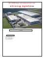
Production and central office in REGAU, AUSTRIA
Contact
Central office:
Römerweg 9
A-4844 Regau, Austria
Telefon: +43(0)7672/72711-0
Fax: +43(0)7672/78805
e-mail: [email protected]