1
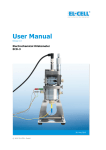
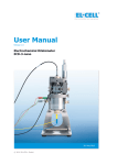
User Manual Release 1.1 Electrochemical Test Cell PAT-Cell 27. March 2015 © 2015 EL-CELL GmbH The information in this manual has been carefully checked and believed to be accurate; however, no responsibility is assumed for inaccuracies. EL-CELL GmbH maintains the right to make changes without further notice to products described in this manual to improve reliability, function, or design. EL -CELL GmbH does not assume any liability arising from the use or application of this product. EL-CELL GmbH Tempowerkring 8 21079 Hamburg - Germany phone: +49 (0)40 790 12 733 fax: +49 (0)40 790 12 736 e-mail: [email protected] web: www.el-cell.com User Manual PAT-Cell – Release 1.1 Page 2 of 32 Content 1 Product Description ................................................................................... 4 2 Features .................................................................................................... 6 3 Safety Precautions .................................................................................... 6 4 Unpacking ................................................................................................. 6 5 Generell Cell Assembly ............................................................................. 10 6 Different Test Cases ................................................................................. 13 6.1 Standard 3-Electrode Test ........................................................................ 15 6.2 Standard 2-Electrode Test ........................................................................ 17 6.3 Three-Electrode Test with Half Cell EIS ...................................................... 19 6.4 Three-Electrode Test with Li Metal Negative ............................................... 20 6.5 Two-Electrode Test with Li Metal Negative .................................................. 23 7 Different gaps of the lower plunger ......................................................... 25 8 PAT-Core Components .............................................................................. 28 9 Disassembly and Cleaning ........................................................................ 29 10 Consumables ............................................................................................ 29 11 Spare Parts .............................................................................................. 30 12 Technical Support .................................................................................... 30 13 Warranty .................................................................................................. 32 User Manual PAT-Cell – Release 1.1 Page 3 of 32 1 Product Description The PAT-Cell is the new leadless housing of the PATCore. Up to 16 PAT-Cells fit into one PAT-Tray. Its small footprint make this combination the ideal choice for high-throughput testing of Li-ion battery materials. The PAT-Tray is covered by a separate manual (http://el-cell.com/downloads/downloads-manuals). PAT-Tray with 16 PAT-Cells The PAT-Core is comprised of three components: 1. Insulation sleeve: The polypropylene insulation sleeve with a ring-shaped reference electrode and a thin technical separator, both pre-installed at the factory, sealed and ready for use in the glovebox. Several other versions are available for special purposes. For two-electrode testing there are additional solutions available. For further information about the different insulation sleeves see chapter 8 of the manual. 2. Lower plunger: The lower plunger serves as the positive current collector. Different sizes are available to match electrodes with different thicknesses and for the additional use of glass fiber separators for half-cell impedance measurements. It will be available in several different materials. For further informa tion see chapter 8 of the manual. 3. Upper plunger: The upper plunger serves as the negative current collector. It will be available in several different materials. For further information see chapter 8 of the manual. The insulation sleeve is a single-use component, which has to be disposed after use. The plungers are available as both single-use components (made of battery grade copper and aluminium) and as reusable components (made of stainless steel 316 L / 1.4404). Upper plunger Insulation sleeve Lower plunger PAT-Cell PAT-Core User Manual PAT-Cell – Release 1.1 Page 4 of 32 Electrical Contacts of the PAT-Cell and Interfacing with the PAT-Tray The PAT-Cell is a leadless 3-electrode test cell, so it does not feature any sockets for direct of cables. Instead, the electrical connection towards the battery tester is made through contact connection areas at the cell bottom, once the PAT-Cell is inserted into one of the sockets of the PAT-Tray. The detail view below shows the five contact areas at the cell bottom (on the right), and the corresponding spring-loaded contact pins in the cell socket of the PAT -Tray. PAT-Tray from top PAT-Cell from below R R 1S 1 2/2S 1/1S: upper electrode (negative), current and sense 2/2S: lower electrode (positive), current and sense R: reference electrode 1 2 The 5 pins in the center are for cell detection and special (future) functions. User Manual PAT-Cell – Release 1.1 Page 5 of 32 2 Features The PAT-Cell is a test cell to accurately characterize aprotic lithium-ion battery materials over long periods of times. The standard PAT-Core is composed of a lithium metal ring reference and a 25 µm thin technical separator (standard: Freudenberg Viledon FS 3005-25, other separators are available on request). Both components are pre-installed in a single-use insulation sleeve. This concept has got several advantages: Ability for conducting long-term measurements with a reliable reference electrode over more than one thousand hours of battery operation . Ability for measuring half cell impedance spectra throughout the battery’s life time. Less mistakes that may result from corrosion or cross-contamination. Increase of testing productivity by single-use concept. No need for cleaning or drying cell components. Fast assembly and dismantling lowers lead times of experiments. Easy and reliable electrolyte filling upon assembly (defined electrolyte volume down to 0.05 cm³). Reliable leakage-proof sealing with PE-Seal and double cutting ring. Reproducible and homogeneous mechanical pressure on electrodes . High precision 18 mm diameter sandwich geometry with a concentricity better than 0.1 mm (electrode and separator dimensions are compatible with other test cells of the ECC series). The PAT-Cell is designed for use with an application in the temperature range from -40° Celcius to +70° Celcius. 3 Safety Precautions Use proper safety precautions when using hazardous elect rode materials and electrolytes. Wear protective glasses and gloves to protect you against electrolyte that may accidentally spill out during disassembly. Upon cell disassembly, dispose all materials properly. Metallic lithium and some insertion compounds may decompose heavily in contact with water and other solvents, and can cause fire. 4 Unpacking Check the contents of the packages against the list given below to verify that you have received all of the required components. Contact EL-CELL, if anything is missing or damaged. NOTE: Damaged shipments must remain within the original packaging for freight company inspection. User Manual PAT-Cell – Release 1.1 Page 6 of 32 List of Components (reusable parts): PAT-Cell test cell, assembled Upper plunger ECC1-01-0026-C, stainless steel 316L (1.4404) Lower plunger ECC1-01-0027-C_50, stainless steel 316L (1.4404), 50 µm gap (for use without additional glass fiber separator) Lower plunger ECC1-01-0027-C_300, stainless steel 316L (1.4404), 300 µm gap (for three-electrode impedance tests; to be used with additional glass fiber separator) Starter Kit (single-use parts)*: Insulation sleeve ECC1-00-0210-A with built-in separator and lithium ring reference Insulation sleeve ECC1-00-0210-B with built-in separator, without lithium ring reference Plain insulation sleeve ECC1-00-0210-D (for 2-electrode tests without built-in separator) Upper plunger ECC1-01-0026-A, copper (E-Cu 58) Lower plunger ECC1-01-0027-A_50, aluminium (99.5% purity), 50 µm gap Lower plunger ECC1-01-0027-A_300, aluminium (99.5% purity), 300 µm gap Glass fiber separator ECC1-01-0012-D, 18 mm x 0.26 mm, 3 pieces * one Starter Kit per order Screw cap, complete Upper plunger Insulation sleeve Lower plunger Cell base (PAT), pre-assembled Button holder, complete User Manual PAT-Cell – Release 1.1 Page 7 of 32 Components Screw cap: Jackshaft (PAT) ECC1-00-0054-C Set screw N_915 Screw cap (PAT) ECC1-00-0225-D Set screw N_913 Screw cap bottom (PAT) ECC1-00-0225-C Retaining ring ECC1-00-0243-A O-Ring DIC9005_ECC1-00-0236-B Lid inset – w/o thread ECC1-00-0231-B Disc spring lid ECC1-00-0233-A Sealing ring ECC1-00-0232-A Compression spring (Au) FED9028 User Manual PAT-Cell – Release 1.1 Page 8 of 32 Components Cell base with PAT-Core: Upper plunger (SS)* ECC1-01-0026-C or Upper plunger (Cu)* ECC1-01-0026-A Lower plunger (SS)* ECC1-01-0027-C_50 (regular) or ECC1-01-0027-C_300 (reduced) Insulation sleeve with built-in separator and with Li-reference ring* ECC1-00-0210-A or Lower plunger (Al)* ECC1-01-0027-A_50 (regular) or ECC1-01-0027-A_300 (reduced) or Insulation sleeve with built-in separator and without Li-reference ring* ECC1-00-0210-B or Plain insulation sleeve* ECC1-00-0210-D DIN7 A1.5x4 cylindrical pin NRM0013 Cell base (PAT) ECC1-00-0234-A Contact pin – long, assy ECC1-00-0242-B Contact pin – short, assy ECC1-00-0242-A Button holder ECC1-00-0247-B Screw N_965 Shaft ring FED9029 Button (PAT) ECC1-00-0253-A User Manual PAT-Cell – Release 1.1 Page 9 of 32 5 Generell Cell Assembly This section describes, how the PAT-Cell has to be assembled in order to conduct proper battery tests. Please note that the assembly has to take place under the protective atmosphere in a glove box. 1. Put the insulation sleeve (6) onto the worktop with the smaller side pointing upwards. 2. Insert the lower electrode (7) into the sleeve with the active layer facing downwards. 3. Put the lower plunger ( 8) onto the lower electrode in the insulation sleeve. 4. Turn the assembly upside down. 5. Align the contact spring of the sleeve with the horizontal contact pin inside the cell base (9). Then insert the assembly into the cell base . 6. Evenly dispense 100 µL of electrolyte (5) on top of the separator with a pipette. 7. Insert the upper electrode (4) into the insulation sleeve with the active layer facing downwards. 8. Insert the upper plunger (3) into the insulation sleeve. 9. Replace the sealing ring (2) at the inside lid of the screw cap. 10. Attach the screw cap (1) to the cell base with the wing nut fully released. 11. Tighten the wing nut of the screw cap clockwise in order to seal the cell [MH1]. 12. Attach the cell into a free socket of the PAT-Tray. 13. The EC-Link software will detect the cell and ask you to start recording. Follow the instructions. 14. Start the electrochemical test of the associated battery tester channel. Operation of the PAT-Tray and the interplay with the connected battery tester are described in more detail in the manual of the PAT-Tray (http://el-cell.com/downloads/downloads-manuals). NOTE: We recommend replacing the sealing ring attached to the lid inside the screw cap right after cell disassembly. The sealing rings must not be heated before use, as they may otherwise no longer fit into the inside lid of the screw cap. HANDLING NOTE: The button holder of the test cell is slightly inwarded, which prevents shortcuts between the cell bottom and the cell base via a potential conductive work surface. Detailed test scenarios are described in chapter 6. User Manual PAT-Cell – Release 1.1 Page 10 of 32 Further recommended tools for working with the PAT-Cell: ECC1-02-0005-A ECC-LiPunch 18 mm ECS1-00-0100-A EL-Cut Cutting Pliers 18 mm 1 Screw cap 2 Sealing ring 3 Upper plunger 4 Upper electrode 5 Electrolyte 6 Insulation sleeve 7 Lower electrode 9 8 Lower plunger 9 Cell base 9 User Manual PAT-Cell – Release 1.1 Page 11 of 32 Spring force in relation to the thickness of the upper electrode: 56 Spring force applied on cell stack / N 54 52 50 48 46 44 42 40 0 200 400 600 800 1000 Thickness of upper electrode / µm User Manual PAT-Cell – Release 1.1 Page 12 of 32 [MH2] 6 Different Test Cases The PAT-Core may be used in many different ways. In the following, four common methods are described, which are very popular and have been extensively tested in our laboratory. All those test methods have in common that the lower plunger is used as the positive current collector, and the upper plunger is used as the negative current collector. The user can choose between single-use (plungers made of Cu 99.9% and/or Al 99.5%) or reuseable components (both plungers made of stainless steel 316 L/1.4404). The gap size of the lower plunger must be chosen so as to match with the thickness of the lower positive electrode and, where applicable, the thickness of an additionally used glass fiber separator. The upper negative electrode can be of any thicknes s. Test Case 1: Standard 3-electrode test with lithium-ion battery electrodes and the built-in separator. This case is most appropriate for the monitoring of half cell potentials during cycle tests. However, half cell impedance measurents will often show artefacts in this case. See page 13 Test Case 2: Standard two-electrode test with lithium-ion battery electrodes and the built-in separator. This case resembles test case 1, but without reference electrode. See page 15 Test Case 3: Three-electrode test optimized for half cell impedance measurement (additionally using glass fiber separator). See page 17 Test Case 4: Three-electrode test with a lithium metal negative. See page 19 Test Case 5: Two-electrode test using a lithium metal negative (no reference electrode). The plain insulation sleeve is used in this test case. See page 21 NOTE: When attached to the PAT-Tray, the PAT-Cell is always operated as a full-cell. This means, the battery tester controls either the cell voltage or the cell current. The reference-electrode makes it possible to record the half-cell voltages simultaneously through the built-in data logger of the PAT-Tray. However, a control of the half-cell voltages is not possible. User Manual PAT-Cell – Release 1.1 Page 13 of 32 User Manual PAT-Cell – Release 1.1 Page 14 of 32 6.1 Standard 3-Electrode Test Components used: ECC1-00-0210-A Insulation sleeve with built-in separator and Li-reference ring (single-use) ECC1-01-0026-C Upper plunger made of stainless steel (reusable) ECC1-01-0027-C_50 Lower plunger made of stainless steel (reusable); 50 µm gap Positive lower electrode, e.g. LCO on Al, 18 mm in diameter, up to 100 µm thick * Negative upper electrode, e.g. graphite on Cu, 18 mm in diameter, any thickness * For thicker electrodes use larger gaps, see table on page 23. Optional single-use plungers: ECC1-01-0026-A Upper plunger made of Cu for negative electrodes operated below 3.0 V vs. Li/Li + (e.g., graphite or silicon in a Li-ion battery) ECC1-01-0026-B Upper plunger made of Al for negative electrodes operated above 1.0 V vs. Li/Li + (e.g., lithium titanate LTO in a Li-ion battery, activated carbon as the negative in an EDLC) ECC1-01-0027-A_50 Lower plunger made of Al for positive electrodes operated above 3.0 V vs. Li/Li + (e.g., lithium cobalt oxide LCO in a Li-ion battery, activated carbon as the positive in an EDLC); 50 µm gap Assembly procedure (inside glove box): 1. Put the insulation sleeve onto the worktop with the smaller side pointing upwards . 2. Insert the positive electrode into the sleeve with the active layer facing downwards. 3. Put the lower plunger (50 µm) onto the positive electrode in the insulation sleeve. 4. Turn the assembly upside down. User Manual PAT-Cell – Release 1.1 Page 15 of 32 5. Align the contact spring of the sleeve with the horizontal contact pin inside the cell base. Then insert the assembly into the cell base. 6. Evenly dispense 100 µL of electrolyte on top of the separator with a pipette. The optimum amount of electrolyte will depend on the thickness and porosity of the electrodes used. 7. Insert the negative electrode into the insulation sleeve with the active layer facing downwards. 8. Insert the upper plunger into the insulation sleeve. 9. Replace the sealing ring at the inside lid of the screw cap. 10. Attach the screw cap to the cell base with the wing nut fully released. 11. Tighten the wing nut clockwise in order to seal the cell. Upper plunger Ring-shaped reference electrode Insulation sleeve Lower plunger User Manual PAT-Cell – Release 1.1 Page 16 of 32 6.2 Standard 2-Electrode Test Components used: ECC1-00-0210-B Insulation sleeve with built-in separator, without reference (single-use) ECC1-01-0026-C Upper plunger made of stainless steel (reusable) ECC1-01-0027-C_50 Lower plunger made of stainless steel (reusable) ; 50 µm gap Positive lower electrode, e.g. LCO on Al, 18 mm in diameter, up to 100 µm thick * Negative upper electrode, e.g. graphite on Cu, 18 mm in diameter, any thickness * For thicker electrodes use larger gaps, see table on page 23. Optional single-use plungers: ECC1-01-0026-A Upper plunger made of Cu for negative electrodes operated below 3.0 V vs. Li/Li + (e.g., graphite or silicon in a Li-ion battery) ECC1-01-0026-B Upper plunger made of Al for negative elect rodes operated above 1.0 V vs. Li/Li + (e.g., lithium titanate LTO in a Li-ion battery, activated carbon as the negative in an EDLC) ECC1-01-0027-A_50 Lower plunger made of Al for positive electrodes operated above 3.0 V vs. Li/Li + (e.g., lithium cobalt oxide LCO in a Li-ion battery, activated carbon as the positive in an EDLC or Li -ion capacitor); 50 µm gap Assembly procedure (inside glove box): 1. Put the insulation sleeve onto the worktop with the smaller side pointing upwards . 2. Insert the positive electrode into the sleeve with the active layer facing downwards. 3. Put the lower plunger onto the positive electrode in the insulation sleeve. 4. Turn the assembly upside down. User Manual PAT-Cell – Release 1.1 Page 17 of 32 5. Align the contact spring of the sleeve with the horizontal contact pin inside the cell base. Then insert the assembly into the cell base . 6. Evenly dispense 100 µL of electrolyte on top of the separator with a pipette. The optimum amount of electrolyte will depend on the thickness and porosity of the electrodes used. 7. Insert the negative electrode into the insulation sleeve with the active layer facing downwards. 8. Insert the upper plunger into the insulation sleeve. 9. Replace the sealing ring at the inside lid of the screw cap. 10. Attach the screw cap to the cell base with the wing nut fully released. 11. Tighten the wing nut clockwise in order to seal the cell. Upper plunger Insulation sleeve Lower plunger [MH3] User Manual PAT-Cell – Release 1.1 Page 18 of 32 6.3 Three-Electrode Test with Half Cell EIS Components used: ECC1-00-0210-A Insulation sleeve with built-in separator and Li-reference ring (single-use) ECC1-01-0026-C Upper plunger made of stainless steel (reusable) ECC1-01-0027-C_300 Lower plunger made of stainless steel (reusable); 300 µm gap ECC1-01-0012-D Glass fiber separators, 18 mm in diameter, thickness 0.26 mm (2 pieces) Positive lower electrode, e.g. LCO on Al, 18 mm in diameter, <100 µm thick* Negative upper electrode, e.g. graphite on Cu, 18 mm in diameter, any thickness * For thicker electrodes use larger gaps, see table on page 23. Optional single-use plungers: ECC1-01-0026-A Upper plunger made of Cu for negative electrodes operated below 3.0 V vs. Li/Li + (e.g., graphite or silicon in a Li-ion battery) ECC1-01-0026-B Upper plunger made of Al for negative electrodes operated above 1.0 V vs. Li/Li + (e.g., lithium titanate LTO in a Li-ion battery, activated carbon as the negative in an EDLC) ECC1-01-0027-A-300 Lower plunger made of Al for positive electrodes operated above 3.0 V vs. Li/Li + (e.g., lithium cobalt oxide LCO in a Li-ion battery, activated carbon as the positive in an EDLC or Li -ion capacitor); 300 µm gap Assembly procedure (inside glove box): 1. Put the insulation sleeve onto the worktop with the smaller side pointing upwards . 2. Insert a glass fiber separator into the insulation sleeve. User Manual PAT-Cell – Release 1.1 Page 19 of 32 3. Insert the positive electrode into the sleeve with the active layer fa cing downwards. 4. Put the lower plunger (300 µm) onto the positive electrode in the insulation sleeve. 5. Turn the assembly upside down. 6. Align the contact spring of the sleeve with the horizontal contact pin inside the cell base. Then insert the assembly into the cell base. 7. Insert another glass fiber separator into the insulation sleeve. 8. Evenly dispense 200 µL of electrolyte on top of the separator with a pipette. The optimum amount of electrolyte will depend on the thickness and porosity of the electrodes used. 9. Insert the negative electrode into the sleeve with the active layer facing downwards. 10. Insert the upper plunger into the insulation sleeve. 11. Replace the sealing ring at the inside lid of the screw cap. 12. Attach the screw cap to the cell base with the win g nut fully released. 13. Tighten the wing nut clockwise in order to seal the cell. Upper plunger Glass fiber separator Ring-shaped reference electrode Insulation sleeve Lower plunger User Manual PAT-Cell – Release 1.1 Page 20 of 32 6.4 Three-Electrode Test with Li Metal Negative Components used: ECC1-00-0210-A Insulation sleeve with built-in separator and Li-reference ring (single-use) ECC1-01-0026-C Upper plunger made of stainless steel (reusable) ECC1-01-0027-C_300 Lower plunger made of stainless steel (reusable); 300 µm gap ECC1-01-0012-D Glass fiber separators, 18 mm in diameter, thickness 0.26 mm (2 pieces) Lower electrode, e.g. LCO on Al or graphite on Cu, 18 mm in diameter, <100 µm thick* Lithium metal disc as upper electrode, 18 mm in diameter, any thickness * For thicker electrodes use larger gaps, see table on page 23. Optional single-use plungers: ECC1-01-0026-A Upper plunger made of Cu for the Li metal electrode ECC1-01-0027-B_300 Lower plunger made of Cu for negative electrodes operated below 3.0 V vs. Li/Li + (e.g., graphite or silicon); 300 µm gap ECC1-01-0027-A_300 Lower plunger made of Al for positive electrodes operated above 3.0 V vs. Li/Li + (e.g., lithium cobalt oxide LCO); 300 µm gap Assembly procedure (inside glove box): 1. Put the insulation sleeve onto the worktop with the smaller side pointing upwards . 2. Insert a glass fiber separator into the insulation sleeve. 3. Insert the positive electrode into the insulation sleeve with the active layer facing downwards. 4. Put the lower plunger (300 µm) onto the positive electrode in the insulation sleeve. User Manual PAT-Cell – Release 1.1 Page 21 of 32 5. Turn the assembly upside down. 6. Align the contact spring at the sleeve with the hor izontal contact pin inside the cell base. Then insert the assembly into the cell base . 7. Insert another glass fiber separator into the sleeve . 8. Evenly dispense 200 µL of electrolyte on top of the separator with a pipette. The optimum amount of electrolyte will depend on the thickness and porosity of the electrodes used. 9. Insert the negative electrode into the sleeve with the active layer facing downwards. 10. Insert the lithium metal negative electrode into the insulation sleeve with the active layer facing downwards. 11. Insert the upper plunger into the insulation sleeve. 12. Replace the sealing ring at the inside lid of the screw cap. 13. Attach the screw cap to the cell base with the wing nut fully released. 14. Tighten the wing nut clockwise in order to seal the cell. Upper plunger Lithium metal negative electrode Glass fiber separator Ring-shaped reference electrode Insulation sleeve Lower plunger User Manual PAT-Cell – Release 1.1 Page 22 of 32 6.5 Two-Electrode Test with Li Metal Negative Components used: ECC1-00-0210-D Plain insulation sleeve (without separator and without Li-reference ring) (single-use) ECC1-01-0026-C Upper plunger made of stainless steel (reusable) ECC1-01-0027-C_50 Lower plunger made of stainless steel (reusable); 50 µm gap ECC1-01-0012-D Glass fiber separators, 18 mm x 0.26 mm (2 pieces) Lower electrode, e.g. LCO on Al or graphite on Cu, 18 mm in diameter Lithium metal disc as upper electrode, 18 mm in diameter * For thicker electrodes use larger gaps, see table on page 23. Optional single-use plungers: ECC1-01-0026-A Upper plunger made of Cu for the Li metal electrode ECC1-01-0027-B_50 Lower plunger made of Cu for negative electrodes operate d below 3.0 V vs. Li/Li + (e.g., graphite or silicon); 50 µm gap ECC1-01-0027-A_50 Lower plunger made of Al for positive electrodes operated above 3.0 V vs. Li/Li + (e.g., lithium cobalt oxide LCO); 50 µm gap Assembly procedure (inside glove box): 1. Put the insulation sleeve onto the worktop with the smaller side pointing upwards . 2. Insert the positive electrode into the insulation sleeve with the active layer facing downwards. 3. Put the lower plunger onto the positive electrode in the insulation sleeve. 4. Turn the assembly upside down. 5. Insert the assembly into the cell base. User Manual PAT-Cell – Release 1.1 Page 23 of 32 6. Evenly dispense 150 µL of electrolyte on top of the separator with a pipette. The optimum amount of electrolyte will depend on the thickness and porosity of the electrodes used. 7. Insert the negative electrode into the insulation sleeve with the active layer facing downwards. 8. Insert the upper plunger into the insulation sleeve. 9. Replace the sealing ring at the inside lid of the screw cap. 10. Attach the screw cap to the cell base with the wing nu t fully released. 11. Tighten the wing nut clockwise in order to seal the cell. [MH4] Lithium metal negative electrode Upper plunger Glass fiber separator Insulation sleeve (plain, no reference) Lower plunger User Manual PAT-Cell – Release 1.1 Page 24 of 32 7 Different gaps of the lower plunger The lower plunger is available in different materials (316L, Al 99.5, Cu 99.9) and with different gaps. The different gaps are necessary in order to account for the different thicknesses of the lower electrode when using an insulation slee ve with a built-in separator. The term ‘gap’ refers to the distance between the lower face of the built -in separator and the upper face of the lower plunger when attached to the insulation sleeve, see sketch below. Gap If you use a wrong plunger gap, you may get trouble with your battery test. The below figures illustrate this point. The gap size must approximate the thickness of the lower electrode (see good case 1 below). When working with additional glass fiber separator, the gap size must approximate the total thickness of the lower electrode and the lower glass fiber separator. (good case 2 on following page). Good case 1: Gap equals thickness of lower electrode -> no bending of built-in separator; reference ring is in plane with separator. User Manual PAT-Cell – Release 1.1 Page 25 of 32 Good case 2: Gap equals thickness of lower electrode plus thickness of additional lower glass fiber separator. Gap too large: excessive downward bending of built-in separator; reference ring is out of plane with separator. Gap too small: excessive upward bending of built-in separator; reference ring is out of plane with separator. User Manual PAT-Cell – Release 1.1 Page 26 of 32 Available gaps of the lower plunger: The lower plunger is available in six standard gaps (see table below). Other gaps are available on request. Both plungers are available in copper (Cu 99.9 / E-CU) or aluminium (99.5) instead of stainless steel. Variant of lower plunger (gap in µm) 50 100 150 200 250 300 Article code lower plunger (SS) ECC1-010027-C_50 ECC1-010027-C_100 ECC1-010027-C_150 ECC1-010027-C_200 ECC1-010027-C_250 ECC1-010027-C_300 Article code lower plunger (Al) ECC1-010027-A_50 ECC1-010027-A_100 ECC1-010027-A_150 ECC1-010027-A_200 ECC1-010027-A_250 ECC1-010027-A_300 Article code lower plunger (Cu) ECC1-010027-B_50 ECC1-010027-B_100 ECC1-010027-B_150 ECC1-010027-B_200 ECC1-010027-B_250 ECC1-010027-B_300 Sample thickness* (µm) 0-100 100-150 150-200 200-250 250-300 300-350 * Thickness of lower electrode (plus thickness of the additional lower glass fiber separator , if applicable). User Manual PAT-Cell – Release 1.1 Page 27 of 32 8 PAT-Core Components The configuration of the PAT-Core is important in order to conduct proper battery tests, as shown in the previous section. All possible configurations of the PAT -Core components are shown in the tables below. Plunger: type of utilization copper Cu 99.9 (single-use vs. reusable) type of testing (2 or 3 electrodes) order no. upper plunger order no. lower plunger* single-use both ECC1-01-0026-A ECC1-01-0027-B* single-use both ECC1-01-0026-B ECC1-01-0027-A* reusable both ECC1-01-0026-C ECC1-01-0027-C* (E-CU 58) aluminium Al 99.5 (EN-AW- 1050) stainless steel 316L (1.4404) * standard gap size “50” – available in 100, 150, 200, 250, 300 (others on request). The number refers to the gap in units of µm. Insulation sleeves: type of utilization order no. (single-use vs. reusable) type of testing (2 or 3 electrodes) Insulation sleeve with lithium metal ring reference, with separator* single-use 3 electrodes ECC1-00-0210-A Insulation sleeve with separator* only single-use 2 electrodes ECC1-00-0210-B Plain insulation sleeve single-use 2 electrodes ECC1-00-0210-D Plain insulation sleeve, disassembled single-use 2 electrodes ECC1-00-0210-F (standard) * standard is Freudenberg Viledon FS 3005-25 (nonwoven polyester pasted with Al 2 O 3 ; 25 µm thick); other separators on request User Manual PAT-Cell – Release 1.1 Page 28 of 32 9 Disassembly and Cleaning After disassembly, dispose all single-use components and electrodes properly. If the cell base has got contaminated with electrolyte, clean it with plenty of water and dry with compressed air. Use less electrolyte for subsequent tests. Plungers made of stainless steel have to be cleaned with plenty of water. If necessary, remove persistent dirt by treating the stainless steel plungers with aqueous nitric acid (20%, 2 hours at room temperature). All other cell components are for immediate re -use without cleaning. 10 Consumables Plunger (single-use): Upper plunger (Al) ECC1-01-0026-B Upper plunger (Cu) ECC1-01-0026-A Lower plunger (Al), gap 50, 100, 150, 200, 250, 300 ECC1-01-0027-A_50 / _100 / _150 / _200 / _250 / _300 Lower plunger (Cu), gap 50, 100, 150, 200, 250, 300 ECC1-01-0027-B_50 / _100 / _150 / _200 / _250 / _300 Separators (single-use): Glass fiber separators (18 mm diameter, 0.26 mm thickness) ECC1-01-0012-D (50 pcs.) Insulation sleeves (single-use): Insulation sleeve with Li-reference ring and separator ECC1-00-0210-A Insulation sleeve with separator only ECC1-00-0210-B Plain insulation sleeve with sECC1-00-0210-D User Manual PAT-Cell – Release 1.1 Page 29 of 32 Seals (single-use): Sealing ring* ECC1-00-0232-A * We recommend to replace the sealing ring after every use. 11 Spare Parts Plunger (reusable): Upper plunger (SS) ECC1-01-0026-C Lower plunger (SS), gap 50, 100, 150, 200, 250, 300 ECC1-01-0027-C_50 / _100 / _150 / _200 / _250 / _300 Further parts[MH5] screw cap: Jackshaft (PAT) ECC1-00-0054-C Set screw Screw cap (PAT) Set screw Screw cap bottom (PAT) Retaining ring O-Ring Lid inset – w/o thread Disc spring lid Compression spring (Au) N_915 ECC1-00-0225-D N_913 ECC1-00-0225-C ECC1-00-0243-A DIC9005_ECC1-00-0236-B ECC1-00-0233-A ECC1-00-0233-A FED9028 User Manual PAT-Cell – Release 1.1 Page 30 of 32 Further parts[MH6] cell base: DIN7 A1.5x4 cylindrical pin Cell base (PAT) Contact pin – long, assy Contact pin – short, assy Button holder Screw Shaft ring Button (PAT) NRM0013 ECC1-00-0234-A ECC1-00-0242-B ECC1-00-0242-A ECC1-00-0247-B N_965 FED9029 ECC1-00-0253-A 12 Technical Support Technical support for this product is exclusively provided by EL-CELL GmbH. EL-CELL GmbH Tempowerkring 8 21079 Hamburg - Germany phone: +49 (0)40 790 12 733 fax: +49 (0)40 790 12 736 e-mail: [email protected] web: www.el-cell.com User Manual PAT-Cell – Release 1.1 Page 31 of 32 13 Warranty For a period of one year from the date of shipment, EL -CELL GmbH (hereinafter Seller) warrants the goods to be free from defect in material and workmanship to the original purchaser. During the warranty period, Seller agrees to repair or replace defective and/or nonconforming goods or parts without charge for material or labor, or, at the Seller’s option, demand return of the goods and tender repayment of the price. Buyer’s exclusive remedy is repair or replacement of defective and nonconforming goods, or, at Seller’s option, the repayment of the price. Seller excludes and disclaims any liability for lost profits, personal injury, interruption of service, or for consequential incidental or special damages arising out of, resulting from, or relating in any manner to these goods. This Limited Warranty does not cover defects, damage, or nonconformity resulting from abuse, misuse, neglect, lack of reasonable care, modification, or the attachment of improper devices to the goods. This Limited Warranty does not cover expendable items. This warranty is void when repairs are performed by a non -authorized person or service center. At Seller’s option, repairs or replaceme nts will be made on site or at the factory. If repairs or replacements are to be made at the factory, Buyer shall return the goods prepaid and bear all the risks of loss until delivered to the factory. If Seller returns the goods, they will be delivered prepaid and Seller will bear all risks of loss until delivery to Buyer. Buyer and Seller agree that this Limited Warranty shall be governed by and construed in accordance with the laws of Germany. The warranties contained in this agreement are in lieu of all other warranties expressed or implied, including the warranties of merchantability and fitness for a particular purpose. This Limited Warranty supersedes all prior proposals or representations oral or written and constitutes the entire understanding regarding the warranties made by Seller to Buyer. This Limited Warranty may not be expanded or modified except in writing signed by the parties hereto. User Manual PAT-Cell – Release 1.1 Page 32 of 32