1
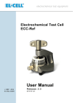
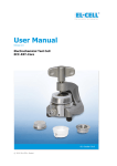
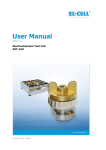
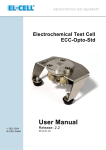
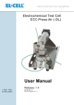
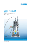
Electrochemical Test Cell ECC-AQU User Manual © 2008-2014 EL-CELL GmbH Release: 2.3 2014-01-30 The information in this manual has been carefully checked and believed to be accurate; however, no responsibility is assumed for inaccuracies. EL-CELL GmbH maintains the right to make changes without further notice to products described in this manual to improve reliability, function, or design. EL-CELL GmbH does not assume any liability arising from the use or application of this product. Contents 1. Product Description........................................................................... 3 2. Features ........................................................................................... 4 3. Safety Precautions ........................................................................... 5 4. Unpacking ........................................................................................ 5 5. ECC Assembly ................................................................................. 7 5.1 AAA Mode ....................................................................................... 7 5.2 AAA Reference Mode...................................................................... 9 5.3 ABA Mode ..................................................................................... 11 5.4 ABA Vacuum Mode ....................................................................... 12 6. Accessories and Spare Parts ......................................................... 14 7. Maintenance ................................................................................... 16 8. Technical Support .......................................................................... 16 9. Warranty ......................................................................................... 17 EL-CELL GmbH Tempowerkring 8 D-21079 Hamburg - Germany phone:+49 (0)40 790 12 733 fax: +49 (0)40 790 12 736 [email protected] www.el-cell.com Page 2 of 17 ECC_AQU_manual / 30/01/2014 1. Product Description The ECC cell design is the result of many years of experience and iterative improvement in battery and supercapacitor electrode testing. It is perfectly suited for voltammetry and impedance as well as cycle life testing. The ECC-Aqu Electrochemical Cell is another member of the modular ECC test cell series, dedicated to the characterization of aqueous battery systems. All metal parts of the ECC-Aqu test cell that come into contact with the electrolyte are made of gold. Other metals like platinum or tantalum are optionally available, and may be easily replaced by the user. The ECC -Aqu cell is equipped with a reference pin assembly to control or monitor half-cell potentials. This manual covers the aqueous test cell ECC-Aqu. A separate manual is available for the two aprotic test cell versions ECC-Std and ECC-Ref. Stainless steel bracket for easy assembly; fits into multi-cell docking station (ECC-Stand) Gold plated spring applies reproducible mechanical load on cell stack (10 … 50 N) Stainless steel lid with 2 mm banana jacks 4-fold cutting rings with PE seal ensure ultra-low leakage PEEK piston with gold wire lead-through towards upper gold current collector PEEK sleeve ensures electrode concentricity and homogeneous current distribution Reference pin assembly PEEK base Gold wire lead-through towards lower gold current collector with 2 mm banana jack Cell stack ECC-Aqu test cell in the AAA reference assembly mode Page 3 of 17 ECC_AQU_manual / 30/01/2014 2. Features High precision 18 mm diameter sandwich geometry with <0.1 mm electrode concentricity Reliable ultra-low leakage with PE seal Temperature operation range -40 to +80 °C (wider ranges on request) Easy and reliable electrolyte filling either upon assembly or afterwards via syringe (vacuum) method Fast assembly and dismantling, and easy cleaning of cell components Electrodes are easily accessible for post-mortem analysis Reusable cell components except for PE sealing Small and defined electrolyte volume down to 0.05 cm 3 Equipped with reference pin assembly for three-electrode operation Adjustable, reproducible and homogeneous mechanical pressure on electrodes Spring Load / N 60 50 FED9021 FED9020 FED9015 (Std) Spring load on stack vs. stack thickness for different springs. Standard is FED9015. 40 30 20 10 0 0.0 0.5 1.0 1.5 Stack Thickness / mm Materials in media contact are gold and PEEK (other materials on request) Modular cell construction with many interchangeable components. “Plug and play” multi-cell fixture available for operation inside temperature chamber or wall mounting, and for connection to a multi-channel potentiostat or battery tester Size (including bracket): 90 mm x 54 mm x 70 mm (height x width x depth) Weight: ca. 600 g Dedicated tools available to ease cell assembly and operation (http://el-cell.com/products/accessories-tools) Page 4 of 17 ECC_AQU_manual / 30/01/2014 3. Safety Precautions Use proper safety precautions when using hazardous electrode materials and electrolytes. Wear protective glasses and gloves to protect you against electrolyte that may accidentally spill out during filling and disassembly. Upon cell disassembly, dispose all materials properly. 4. Unpacking Check the contents of the packages against the list given below to verify that you have received all of the components. Contact the factory if anything i s missing or damaged. NOTE: Damaged shipments must remain with the original packaging for freight company inspection. Purchased parts package: ECC-Aqu (ECC1-00-0006-A): 1. ECC1-00-0200-A 2. ECC1-00-0068-A 3. ECC1-00-0057-A 4. ECC1-00-0130-B 5. ECC1-00-0058-A 6. ECC1-00-0080-A 7. ECC1-00-0053-A 8. FED9015 Cell bracket /wing nut, assembly Cell base (aqueous) Cell lid PTFE plug Sleeve (Std) Central upper piston (aqueous) PE Seal Compression spring (gold plated) Accessories kit (ECC1-00-0303-A): 9. ECC1-00-0010-C Reference pin (Au) [for 3-electrode operation; replaces PTFE plug assembly] 10. ECC1-00-0058-B Sleeve (Ref) [for 3-electrode operation; replaces Std-sleeve] 11. ECC1-00-0091-A Adjustment tool (for ECC-Aqu) [for electrode alignment in the ABA assembly mode] 12. ECC1-00-0061-A Locking washer 13. WZG9005 allen wrench 0.9 mm 14. ECC1-00-0069-A Current collector (Au) 15. ECC1-00-0092-A Sleeve removing tool 16. ECC1-00-0053-A PE seal (10 pcs.) 17. ECC1-01-0012-C Glass fiber separator 18 x 1.55 mm (10 pcs.) 18. ECC1-00-0022-B Separator (Celgard 2325) 20 x 0.025 mm (10 pcs.) (picture: see next page) Page 5 of 17 ECC_AQU_manual / 30/01/2014 Page 6 of 17 ECC_AQU_manual / 30/01/2014 5. ECC Assembly The ECC electrochemical cell may be operated in several modes which differ in the size of the components used (diameter and thickness), and in the way the cell is filled with electrolyte (dropping onto separator during assembly, or vacuum filling afterwards). NOTE: In order to remove oxygen, the fully assembled cell – with the side opening unplugged – may be out-gassed in a vacuum oven prior to filling it with de-aerated electrolyte via the syringe method. Assembly and filling in a glove box is possible as well. 5.1 AAA Mode In this mode the cell is assembled with a thick fiber cloth separator having the same 18 mm diameter as the two adjacent electrodes, and a thickness of between 0.2 and 2 mm. The cell is filled with the electrolyte during assembly by dropping a given volume of electrolyte directly onto the separator (0. 1 to 1 ml, depending on the separator and electrodes used). Only when applying the spring load upon final cell closure, a defined amount of electrolyte is squeezed out of the separator and soaks the two adjacent electrodes. The confinement of the cell stack by an insulating sleeve ensures a homogeneous current distribution and thus makes this configuration ideal for impedance measurements. Upper Electrode Separator Lower Electrode Assembly Steps: i) ii) iii) iv) v) vi) Close the side opening of the cell base with the provided plug. Insert the piston into the STD sleeve and hold the piston/sleeve assembly with the contact face of the piston pointing upwards. Place the gold current collector disc, the working electrode and the fiber cloth separator on top of the piston inside the sleeve. Dispense a defined amount of electrolyte onto the separator. Place the counter electrode and finally the second gold current collector on top of the stack inside the sleeve. Push the cell base over the assembly, press onto the piston, and turn the cell into the upright position. Page 7 of 17 ECC_AQU_manual / 30/01/2014 vii) viii) Insert the spring and the PE seal. Attach the cell lid, insert the cell into the bracket, and tighten the wing nut. Note: The appropriate amount of electrolyte depends on the porosity and thickness of the components used, and thus has to be determined in pre tests. The amount must be smaller than the absorption capacity of the separator in its uncompressed state. 0.5 mL of electrolyte is a good starting value when using the 1.5 mm thick standard separator and electrodes of around 0.1 mm thickness. Wing nut Bracket Lid Spring PE seal Std sleeve Piston Cell base Plug assembly Cell stack ECC-AQU test cell in the AAA assembly mode Page 8 of 17 ECC_AQU_manual / 30/01/2014 5.2 AAA Reference Mode In the reference mode, a metal pin is to be positioned close to the separator edge in between the working and the counter electrode. This metal pin can either function directly as the reference electrode (e.g. when using a silver wire coated with silver chloride), or the inert metal pin makes the electronic contact with some reference material that is to be loaded upfront into the feed-through hole of the REF sleeve. The ECC-AQU test cell is equipped for the second case, and the corresponding cell assembly is described below. The reference material has to be provided by the user. We have good experience with using PTFE bound activated carbon as the reference material when working with neutral and acidic electrolytes (not suited for alkaline electrolytes). Depending on the type of reference material used it may be advised to enlarge the small feed-through hole of the REF sleeve (0.3 mm diameter standard) with the aid of a hand drill, or to pre-load the small feedthrough hole of the REF sleeve with a piece of fiber cloth (serving as an electrolyte “wick”). Please consult us for more specific information. Note that the use of conventional reference electrodes is restricted by the narrow diameter of the feed-through hole in the cell base which is only 1.6 mm. Upper Electrode Separator 0.9 mm Lower Electrode Assembly Steps: i) Load the feed-through hole of the REF sleeve with a small piece of the fiber cloth (if applicable) and subsequently the reference material. A dedicated tool, the ECC-RefLoad, is optionally available to ease this assembly step (http://el-cell.com/products/accessories-tools/ecc-load) ii) Insert the piston into the sleeve and hold the piston/sleeve assembly with the contact face of the piston pointing upwards. Place the gold current collector disc, the working electrode and the fiber cloth separator on top of the piston inside the sleeve. Chose the thickness of the separator so as to avoid a short circuit between the reference and one of the two sandwich electrodes. Dispense a defined amount of electrolyte onto the separator. Place the counter electrode and finally the second gold current c ollector on top of the stack inside the sleeve. Push the cell base over the assembly, press onto the piston, and turn the cell into the upright position. Mount the locking ring, the spring, and the PE seal. Screw the reference assembly into the side opening of the cell base. Attach the cell lid, insert the cell into the bracket, and tighten the wing nut. iii) iv) v) vi) vii) viii) ix) Page 9 of 17 ECC_AQU_manual / 30/01/2014 Wing nut Bracket Lid Spring REF sleeve Locking washer Cell base Piston Reference pin assembly Cell stack ECC-AQU test cell in the AAA mode with reference pin assembly Detail view of the reference pin assembly Page 10 of 17 ECC_AQU_manual / 30/01/2014 5.3 ABA Mode In the ABA mode the cell is assembled with a thin separator that is larger in diameter than the two adjacent electrodes so as to prevent a short circuit along the edge of the thin separator. An alignment tool is provided to ensure concentricity of the two sandwich electrodes upon assembly. Upper Electrode Separator Lower Electrode Assembly Steps: i) ii) iii) iv) v) vi) vii) viii) ix) x) Close the side opening of the cell base with the provided plug. Insert the piston into the sleeve and hold the piston/sleeve assembly with the contact face of the piston pointing upwards. Place the gold current collector disc and the working electrode on top of the piston inside the sleeve. Dispense a defined amount of electrolyte onto the electrode. About 0.3 mL of electrolyte is appropriate for 0.1 mm thick components (electrodes and separator). Place the 20 mm separator on top of the wetted electrode. Make sure that the electrode is fully covered by the separator. Attach the provided alignment tool and insert the counter electrode and finally the second gold current collector on top of the stack. Detach the alignment tool. Push the cell base over the assembly, press onto the piston, and tur n the cell into the upright position. Mount the spring and the PE seal. Attach the cell lid, insert the cell into the bracket, and tighten the wing nut. Page 11 of 17 ECC_AQU_manual / 30/01/2014 5.4 ABA Vacuum Mode The ABA vacuum mode is recommended when working with experimental electrolytes that do not easily wet the electrodes or separator used. O-ring seals are to be mounted to both piston and STD sleeve in order to apply vacuum during the final electrolyte filling procedure. Note that the O-ring seals and the syringe/transfer line required for vacuum filling have to be ordered separately. Assembly Steps: i) ii) iii) iv) v) vi) vii) viii) ix) x) Mount O-ring seals to piston and STD sleeve. Leave the side opening of the cell base unplugged. Insert the piston into the sleeve and hold the piston/sleeve assembly with the contact face of the piston pointing upwards. Place the gold current collector disc and the working electrode on top of the piston inside the sleeve. Place the 20 mm separator into the recess of the sleeve on top of the dry electrode. Make sure that the electrode is fully covered by the separator. Attach the provided alignment tool and insert the counter electrode and finally the second gold current collector on top of the stack. Detach the alignment tool Push the cell base over the assembly, press onto the piston, and turn the cell into the upright position. Mount the spring and the PE seal. Attach the cell lid, insert the cell into the bracket, and tighten the wing nut. Fill the cell by means of the syringe (vacuum) method according t o the following procedure. a. Charge a 5 ml syringe with ca. 0.3 ml of electrolyte. b. Connect the syringe via the transfer line to the side opening of the cell. c. Push the syringe piston back to evacuate the cell. Hold the piston a few seconds in the strained position. d. Hold the syringe with the piston upwards, and release the piston so that the electrolyte is drawn into the cell. e. Repeat the two previous steps to complete filling if necessary. f. Remove the syringe together with the transfer line, and close the cell with the provided plug. Page 12 of 17 ECC_AQU_manual / 30/01/2014 Wing nut Syringe Bracket Lid PE seal Std sleeve Piston Internal O-Ring seals Cell base Transfer line ECC test cell in the ABA vacuum mode Page 13 of 17 ECC_AQU_manual / 30/01/2014 6. Accessories and Spare Parts ECC-AQU with syringe for vacuum filling Page 14 of 17 ECC_AQU_manual / 30/01/2014 ECC-AQU with reference pin assembly Page 15 of 17 ECC_AQU_manual / 30/01/2014 7. Maintenance Right after disassembly, all materials used have to be disposed properly. All wetted parts are to be cleaned with an appropriate detergent wash and solvent (water, ethanol, or acetone). The transfer line used for filling the cells is to be purged with the aid of a syringe. All parts are to be dried immediately after cleaning in vacuum at 80°C. PE seals and O-rings are to be replaced. NOTE: Leaving cell parts in contact with ambient atmosphere while still being wetted with electrolyte may result in severe corrosion. 8. Technical Support Technical support for this product is exclusively handled by EL-CELL GmbH. The following procedure must be followed when the ECC test cell or any p art of it is returned to EL-CELL GmbH for repair: 1. Send an e-mail to [email protected] to obtain a return authorization number and a decontamination report form. 2. Sign the decontamination report asserting that the instrument has been decontaminated and is safe for technicians to work on it. 3. Describe in detail what is wrong. 4. Include a contact name, address, telephone number, and email address. 5. Return the equipment to EL-CELL GmbH Tempowerkring 8 D-21079 Hamburg Germany Email: [email protected] Web: www.el-cell.com Page 16 of 17 ECC_AQU_manual / 30/01/2014 9. Warranty For a period of one year from the date of shipment, EL-CELL GmbH (hereinafter Seller) warrants the goods to be free from defect in material and workmanship to the original purchaser. During the warranty period, Seller agrees to repair or replace defective and/or nonconforming goods or parts without charge for material or labour, or, at the Seller’s option, demand return of the goods and tender repayment of the price. Buyer’s exclusive remedy is repair or replacement of defective and nonconforming goods, or, at Seller’s option, the repayment of the price. Seller excludes and disclaims any liability for lost profits, personal injury, interruption of service, or for consequential incidental or special damages arising out of, resulting from, or relating in any manner to these goods. This Limited Warranty does not cover defects, damage, or nonconformity resulting from abuse, misuse, neglect, lack of reasonable care, modification, or the attachment of improper devices to the goods. This Limited Warranty does not cover expendable items. This warranty is void when repairs are performed by a non-authorized person or service centre. At Seller’s option, repairs or replacements will be made on site or at the factory. If repairs or replacements are to be made at the factory, Buyer shall return the goods prepaid and bear all the risks of loss until delivered to the factory. If Seller returns the goods, they will be delivered prepaid and Seller will bear all risks of loss until delivery to Buyer. Buyer and Seller agree that this Limited Warranty shall be governed by and construed in accordance with the laws of Germany. The warranties contained in this agreement are in lieu of all other warranties expressed or implied, including the warranties of merchantability and fitness for a particular purpose. This Limited Warranty supersedes all prior proposals or representations oral or written and constitutes the entire understanding regarding the warranties made by Seller to Buyer. This Limited Warranty may not be expanded or modified except in writing signed by the parties hereto. Page 17 of 17 ECC_AQU_manual / 30/01/2014