1
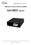
MaxBox SOLAR User manual Version 2.3.10 EN
USER MANUAL AND INSTALLATION
GUIDE
1
Alleantia s.r.l.
2014
All rights reserved.
MaxBox SOLAR User manual Version 2.3.10 EN
1 Contents
USER MANUAL AND INSTALLATION GUIDE............................................................................ 1
2
3
4
Device switching on and access mode................................................................................... 5
2.1
Switching on/off .............................................................................................................. 5
2.2
Local access ................................................................................................................... 5
2.3
Access via Wi-Fi dongle.................................................................................................. 6
2.4
Ethernet LAN access ...................................................................................................... 7
2.4.1
Direct connection to a PC ........................................................................................ 7
2.4.2
Connection to an existing LAN network ................................................................. 14
Installation and wiring .......................................................................................................... 15
3.1
Use of the built-in serial ports........................................................................................ 15
3.2
Use of the USB-serial converters .................................................................................. 16
3.3
Use of MODBUS Ethernet Serial converters ................................................................. 16
3.4
Wiring an RS485 network ............................................................................................. 16
System configuration ........................................................................................................... 18
4.1
Ethernet LAN network configuration (Appliance version only) ....................................... 19
4.2
Internet communication test .......................................................................................... 20
4.3
Port and communication parameters configuration ....................................................... 21
4.3.1
4.4
Serial ports detection ............................................................................................. 22
System devices configuration ....................................................................................... 23
4.4.1
Adding new devices ............................................................................................... 23
4.4.2
Removing a device ................................................................................................ 25
4.4.3
Installation support manuals .................................................................................. 26
4.5
Custom measures......................................................................................................... 27
4.6
General settings............................................................................................................ 28
4.7
Email and SMS notifications ......................................................................................... 29
4.8
Password change ......................................................................................................... 31
2
Alleantia s.r.l.
2014
All rights reserved.
MaxBox SOLAR User manual Version 2.3.10 EN
4.9
4.9.1
Customized measures in home page ..................................................................... 32
4.9.2
Customization of chart scale .................................................................................. 35
4.10
Logos and title customization ........................................................................................ 36
4.11
Documents ................................................................................................................... 37
4.12
Favorites ....................................................................................................................... 38
4.13
Configuration of measures read by the devices ............................................................ 39
4.13.1
Measures offset ..................................................................................................... 40
4.13.2
Measure scaling .................................................................................................... 41
4.14
5
6
Configuration of the home page .................................................................................... 32
Custom alarms.............................................................................................................. 42
User interface ...................................................................................................................... 46
5.1
Home (synoptic)............................................................................................................ 46
5.2
System measures display ............................................................................................. 47
5.2.1
Graphs................................................................................................................... 50
5.2.2
Exporting data to Excel .......................................................................................... 51
5.3
Alarms .......................................................................................................................... 52
5.4
Alarms history ............................................................................................................... 53
5.5
Report generation ......................................................................................................... 55
5.5.1
Energy reports ....................................................................................................... 55
5.5.2
UTF report ............................................................................................................. 57
UTF report configuration ...................................................................................................... 58
6.1
Fiscal meter reading devices configuration ................................................................... 58
6.1.1
Reading configuration via MaxEye and pulse meter .............................................. 58
6.1.2
Reading configuration via network analyzers ......................................................... 61
6.2
Measure alignment configuration .................................................................................. 62
6.3
Energy configuration for the UTF report ........................................................................ 62
6.3.1
7
Examples of energy report configurations .............................................................. 64
FTP remote backup ............................................................................................................. 66
3
Alleantia s.r.l.
2014
All rights reserved.
MaxBox SOLAR User manual Version 2.3.10 EN
7.1
Details of the transferred files ....................................................................................... 66
8
Dropbox account.................................................................................................................. 68
9
Modbus Gateway ................................................................................................................. 72
9.1
Rules of automatic mapping.......................................................................................... 72
10
Technical data .................................................................................................................. 74
11
Troubleshooting - FAQ ..................................................................................................... 75
11.1
Unable to complete Internet communication test........................................................... 75
11.2
Communication problems with serial devices ................................................................ 75
11.3
Unable to access MaxBox from the local network ......................................................... 75
11.4
Unable to access MaxBox from the internet network .................................................... 75
12
Contacts ........................................................................................................................... 76
4
Alleantia s.r.l.
2014
All rights reserved.
MaxBox SOLAR User manual Version 2.3.10 EN
2 Device switching on and access mode
The MaxBox SOLAR is supplied ready to use for the monitoring of solar plants and of all devices
that can usually be associated with these.
2.1 Switching on/off
The MaxBox can be switched on and off via the button (with blue light when on) at the front of the
device.
CAUTION:
To avoid damaging the data on your hard disk due to a crash, do not remove the power
supply until the system is completely switched off. The installation of a UPS to avoid
possible damage in case of abnormal interruption in the power supply is recommended.
The complete system and monitoring application start-up is confirmed by the emission of 3
consecutive beeps. From that moment on you can access the web interface and proceed with
the configuration. If the system has already been configured you can begin to interrogate the
devices.
If the device fails to issue the 3 beeps, there may be a problem, in which case contact the vendor
for assistance.
The MaxBox is turned on automatically as soon as it is connected to the power supply, if
previously turned on, in order to enable the automatic restart of the device in the event of a
temporary interruption in the electricity supply.
2.2 Local access
By connecting to a monitor with HDMI interface and a USB mouse and keyboard, it is possible to
proceed with the configuration described in the following paragraphs without using another
terminal.
The peripherals can be connected even after the device is turned on and it is recommended that
the front USB ports are used, leaving the rear ports open for the installation of USB-serial
converters.
5
Alleantia s.r.l.
2014
All rights reserved.
MaxBox SOLAR User manual Version 2.3.10 EN
2.3 Access via Wi-Fi dongle
The Wi-Fi dongle (optional) present in the Alleantia catalogue allows you to turn the MaxBox into
an Access Point, or to create a wireless network to which your PC, tablet and smartphone can
connect and display the web monitoring interface, enabling the configuration of the system and
the display of the data without the use of external routers or without changing the network
configuration of the device from which you want to connect.
To install the dongle just plug it into a free USB port, preferably a front port in order to leave the
rear ports intended for USB-serial converters free, and wait for the beep to confirm successful
installation.
Then, connect to the network using the following data:
Wi-Fi (SSID) network name: maxbox
Password: MaxBoxWIFI
Once connected, access the web interface of the MaxBox using the preferred internet browser
and typing the URL in the address bar:
http://maxbox
or alternatively
http://10.10.0.1
CAUTION:
The Wi-Fi network allows you to connect exclusively to the MaxBox and to display its
monitoring interface. For safety reasons, it is not possible to access any other devices
connected to the MaxBox via the wired LAN network.
6
Alleantia s.r.l.
2014
All rights reserved.
MaxBox SOLAR User manual Version 2.3.10 EN
2.4
Ethernet LAN access
MaxBox default Ethernet LAN configuration is as follows:
IP address: 192.168.1.29
Subnet mask: 255.255.255.0
Gateway: 192.168.1.1
DNS 1: 208.67.222.222
DNS 2: 208.67.220.220
The DNS are necessary for the functioning of the remote support network.
2.4.1
Direct connection to a PC
This procedure requires a direct link (point to point) to a PC via an Ethernet cable, not
necessarily twisted. The network configuration of the PC to which the MaxBox is connected
must have:
•
192.168.1.nnn (with n between 2 and 254, with the exception of 29, which is already used
by MaxBox) type Static IP
•
subnet mask 255.255.255.0
If this is not the case, the configuration of the PC must be changed by following the directions in
the following paragraphs.
Then, it will be possible to access the web interface of the MaxBox using the preferred internet
browser and entering the following URL in the address bar:
http://192.168.1.29
2.4.1.1 Configuration for Windows XP
•
Access the “Start” menu and then click on “Control panel”
7
Alleantia s.r.l.
2014
All rights reserved.
MaxBox SOLAR User manual Version 2.3.10 EN
•
Click on “Network connections”
•
Select the connection to be amended (usually "Local area connection (LAN)"). Click
mouse right button and select "Properties".
8
Alleantia s.r.l.
2014
All rights reserved.
MaxBox SOLAR User manual Version 2.3.10 EN
•
Select “Internet Protocol (TCP/IP)” and click on ”Properties”
•
Set the network parameters as in the figure, namely:
IP address: 192.168.1.5
Subnet mask: 255.255.255.0
9
Alleantia s.r.l.
2014
All rights reserved.
MaxBox SOLAR User manual Version 2.3.10 EN
2.4.1.2 Configuration for Windows 7
•
Access the “Start” menu and then click on “Control panel”
•
Click on “Network and Internet”
10
Alleantia s.r.l.
2014
All rights reserved.
MaxBox SOLAR User manual Version 2.3.10 EN
•
Click on “Network and sharing center”
•
Click on “Change adapter settings”
•
Select the connection to be amended, usually "Local area connection (LAN)". Click mouse
right button and select "Properties".
11
Alleantia s.r.l.
2014
All rights reserved.
MaxBox SOLAR User manual Version 2.3.10 EN
•
Select "Internet protocol version 4 (TCP/IPv4)" and click on “Properties”
•
Set the network parameters as in the figure, namely:
IP address: 192.168.1.5
Subnet mask: 255.255.255.0
12
Alleantia s.r.l.
2014
All rights reserved.
MaxBox SOLAR User manual Version 2.3.10 EN
13
Alleantia s.r.l.
2014
All rights reserved.
MaxBox SOLAR User manual Version 2.3.10 EN
2.4.2
Connection to an existing LAN network
In this case it is necessary that the default IP address is compatible with those in the existing
network. If so, a direct connection to your switch / router is sufficient, otherwise the MaxBox
network configuration must be changed.
For Appliance version follow the procedure described in paragraph 19. For the software version
use the Windows interface as in paragraphs 2.4.1.1 and 2.4.1.2.
The configuration of the network to assign to MaxBox cannot be determined beforehand.
Please, contact your reference system engineer to obtain the necessary parameters.
Once you have obtained the network configuration to assign to MaxBox, edit it by accessing the
web interface via one of the methods described in paragraphs 2.2, 2.3 or 2.4.1, and then connect
the MaxBox to the existing LAN.
In the event that the LAN is equipped with a firewall configured to block access to the Internet
network unless specific rules are defined, a list of the TCP and UDP ports used by MaxBox,
which must necessarily be open to outbound traffic, to ensure proper operation, is provided
below:
•
123 TCP (NTP) to synchronise the date and time
•
53 UDP (DNS) for domain names resolution, which is essential for the connection to the
remote support VPN
•
443 TCP and 1194 UDP for the connection to the remote support VPN
•
21 TCP (FTP) for remote backup on FTP if enabled on a server not within the LAN
network
•
25 TCP (SMTP) to send email notifications if enabled by a server not within the LAN
network. Some SMTP servers may use a different TCP port. In this case open the specific
port to traffic
If you want to remotely view the Web interface, enable the port to inbound traffic:
•
80 TCP (HTTP)
14
Alleantia s.r.l.
2014
All rights reserved.
MaxBox SOLAR User manual Version 2.3.10 EN
3 Installation and wiring
3.1 Use of the built-in serial ports
The MaxBox has two serial ports in the rear, one RS485 called COM1 and one RS232 called
COM2, neither of which is optically isolated.
These ports should not be used to create very long lines especially outdoors, as they are not
protected against overloads and EMC interference.
Figure 1 - Rear view of the MaxBox
The RS485 serial pinout is indicated on the terminals themselves, while the pinout of the RS232
serial with DB9 connector is shown in Figure 2 - Pinout connector DB9 RS232:
Figure 2 - Pinout connector DB9 RS232
15
Alleantia s.r.l.
2014
All rights reserved.
MaxBox SOLAR User manual Version 2.3.10 EN
3.2 Use of the USB-serial converters
Should you need to use several serial communication lines, or should you prefer to have them
optically isolated, a compatible interface converter from those in the Alleantia catalogue must be
used. These converters can be either optically isolated (up to 3 kV) or without galvanic insulation.
The first solution is always to be preferred for any installation for extra protection against
overloads and EMC interference, but it becomes absolutely necessary when the RS485 serial
cable must be laid outside, and is therefore exposed to lightning.
CAUTION:
USB-serial converters must be connected to the rear USB ports, and the name of the serial
port that will be created depends on the USB port to which the converter is connected.
This is indicated on the sticker on the upper part of the case.
It is not necessary to install any drivers to use these converters. Simply connect them to MaxBox
with a special USB cable, wait for the beep to confirm successful installation and carry out
the serial ports detection procedure described in paragraph 4.3.1.
3.3 Use of MODBUS Ethernet Serial converters
The Ethernet Serial converters for the Modbus protocol are devices that not only change the
physical transmission medium, but also perform the additional functions of converting the protocol
from Modbus TCP / IP to Modbus RTU. So, the MaxBox will have access to the devices
downstream of these converters configuring them as directly connected to the Ethernet interface
CAUTION:
Ethernet Serial converters cannot be used for protocols other than Modbus.
3.4 Wiring an RS485 network
There are a few simple rules that make RS485 serial connection reliable.
•
The cable used must be shielded, with the shield grounded at one end only.
•
Star configurations are not allowed. Only linear ones are, as shown in Figure 3. The line
should be terminated at the end (the master, or the MaxBox, is not necessarily at an end
of the line) with a suitable resistance which can often be inserted by means of a selector
switch on the devices themselves. If the non-optically isolated RS485 serial port on the
MaxBox is used, you can possibly take advantage of the internal termination bridging the
terminals D and T as in Figure 4.
16
Alleantia s.r.l.
2014
All rights reserved.
MaxBox SOLAR User manual Version 2.3.10 EN
R=120Ω
R=120Ω
Figure 3 - RS485 wiring diagram
Figure 4 - Built-in RS485 with internal termination activated (bridge between the terminals D and T). If you do
not want to use the termination do not bridge the terminals
•
A separate communication line must be realised for each communication protocol used in
the system. For example, if you have network analyzers that use Modbus RTU and
inverters that use a proprietary protocol, you will need two separate cables and an equal
number of USB-serial converters.
Additional information can be found in the troubleshooting guide in the section "Installation" ->
"Devices configuration" that can be downloaded by pressing the button:
17
Alleantia s.r.l.
2014
All rights reserved.
MaxBox SOLAR User manual Version 2.3.10 EN
4 System configuration
The configuration consists in the identification of the components that are physically connected to
MaxBox, in the description of the connections and any graphical customizations of the interface.
Access the "Configuration" section from the main navigation bar and enter the following
credentials:
User name: admin
Password: webloggerSU
A screen will appear as in Figure 5:
Figure 5 – System configuration
18
Alleantia s.r.l.
2014
All rights reserved.
MaxBox SOLAR User manual Version 2.3.10 EN
4.1 Ethernet LAN network configuration (Appliance version only)
If the MaxBox is connected to a LAN network where there are also other devices, its default
network configuration could lead to a conflict. If this happens, the network settings of the MaxBox
must be changed in the "Communication" -> "TCP / IP Configuration" section. A screen as shown
in Figure 6 will be displayed:
Figure 6 - Network configuration
If there is a DHCP server in the LAN network to which the MaxBox is connected, you can check
the "Use DHCP" box and press the "Save" button. The MaxBox will take the IP configuration
directly from the DHCP server.
If the DHCP server is not available or you prefer to manually set the configuration, remove the
check mark in the "Use DHCP" box and enter all the "IP Parameters" including the IP addresses
of the DNS servers that may coincide with that of the gateway in simple network configuration.
CAUTION:
Changes to the network configuration become effective ONLY AFTER the rebooting of the
MaxBox hardware
The right area "Network Interface" displays the current network configuration for both the wired
interface (LAN) as well as the Alleantia VPN (Virtual Private Network) through which the MaxBox
communicates with any centralised server (optional service).
19
Alleantia s.r.l.
2014
All rights reserved.
MaxBox SOLAR User manual Version 2.3.10 EN
If the network to which you are connected has internet access, refer to paragraph
4.2 to verify the correctness of the LAN configuration set.
4.2 Internet communication test
Figure 7 - Internet communication test
In the "Communication" - > "TCP / IP test" section the correctness of the LAN configuration to the
outside (internet network) can be verified by testing the reachability of some default hosts and
others of your choice.
By pressing the "Test" button next to each host, or, alternatively, the "Test all" one, the
reachability of these hosts can be verified and the result of the test will be shown in the "Host
state” column. In the event that the host cannot be reached, check the configuration of the
MaxBox LAN network, the network wiring or contact your network administrator.
20
Alleantia s.r.l.
2014
All rights reserved.
MaxBox SOLAR User manual Version 2.3.10 EN
4.3
Port and communication parameters configuration
The default configuration of the ports is carried out in the section “Communication” -> “COM and
Ethernet configuration” and is illustrated in Figure 8.
Figure 8 - Communication ports configuration
CAUTION:
The MaxBox is preconfigured for the use of the internal serial ports. If you have one or
more USB-serial converters, the detection procedure described in paragraph 4.3.1 must be
performed in order to use them.
The configuration must be modified according to the characteristics of the connected devices,
referring to their installation manuals.
The system provides for the polling of all devices on each communication line, inserting a pause
between one cycle and the next equal to the "Poll pause (ms)” value.
In the event that the polling of a device is not successful within the "Timeout (ms)", the system
performs a number of attempts equal to "Retries" before highlighting a communication error and
moving on to the next device.
In the event of communication problems, increase this value by up to a few seconds in order to
avoid under-performing electronic systems being overloaded by the repeated polling.
The non-functioning device will be called up in each scan cycle.
21
Alleantia s.r.l.
2014
All rights reserved.
MaxBox SOLAR User manual Version 2.3.10 EN
4.3.1
Serial ports detection
If an additional USB-serial converter is installed, the system must be prepared for its use by
performing the following detection procedure:
1. Insert the USB-serial converter, even with the MaxBox functioning
2. Wait approximately 10 seconds
3. Press the “Scan serial port” button
The new ports will appear with a green background:
Figure 9 - New serial port
CAUTION:
If a USB-serial converter is removed and the procedure for serial port detection is started,
the corresponding port will appear with a red background.
Proceed to the configuration of the port parameters and press "Apply Changes".
A serial port can be disabled by pressing the “Deactivate” button, in which case it
will no longer be possible to use it during the procedure described in section 4.4
In order to identify to which USB-serial converter a COM port is associated see the
adhesives on the MaxBox.
22
Alleantia s.r.l.
2014
All rights reserved.
MaxBox SOLAR User manual Version 2.3.10 EN
4.4
4.4.1
System devices configuration
Adding new devices
Figure 10 - System devices configuration
All of the devices in the system from which you want the MaxBox to collect measures must be
inserted in the section "Installation" -> "Devices configuration".
To add a device, press the "Add" button and a popup window will appear as in Figure 11:
Figure 11 - List of supported devices
The list contains all of the devices supported by MaxBox and can be sorted and filtered by
manufacturer, model and version in order to facilitate the search. For inverters the rated power is
also indicated, given that it contributes to the limitation of the license.
To add a device to the system configuration, select it, set the number of devices present and
press the "Add" button. The number of devices selected will be inserted in the main page and will
appear with a green background to indicate that they have just been added:
23
Alleantia s.r.l.
2014
All rights reserved.
MaxBox SOLAR User manual Version 2.3.10 EN
Figure 12 - New devices added
The MaxBox now knows the topology of the system with the type and number of devices present.
Each one must be assigned a unique name to recognise it in the user interface (e.g. West
Inverter 1), a unique numeric identifier to allow addressing on the RS232/485 bus or Ethernet (the
ID in the case of the Modbus protocol) and the communication port on which to poll it.
The parameters of a device can be inserted directly in the line of the device itself. The "IP
Address" and "TCP / UDP Port" fields will also be completed for the devices with Ethernet
interface which, in the case of Modbus TCP / IP, is generally “502”.
Repeat the operation for all devices on the page.
CAUTION:
The identifier must be assigned to the first device (e.g. inverter) according to the
procedure described in the device’s manual, and then copied in the configuration section
of the MaxBox.
The devices with "<disconnected>" communication port are not "polled" as they
are not associated with any communication line (Ethernet or serial). If a device is
out of service its communication port can be set to "<disconnected>" to avoid
any communication errors and speed up the reading of data from the system
without losing the configuration entered.
Once the system configuration is complete, press the "Apply Changes" button at the top to make
the changes effective.
After a few moments the MaxBox will begin to poll the devices and an icon will appear next to
each representing the communication status with the device itself.
24
Alleantia s.r.l.
2014
All rights reserved.
MaxBox SOLAR User manual Version 2.3.10 EN
If the configuration and wiring are correct the icon will be green:
reachable the icon will be red:
while if the device is not
.
Figure 13 - System configured
The measures collected by the devices will appear in the "Devices" section in the main menu, see
paragraph 5.2. Each device provides a number of measures that can be appropriately chosen by
the user to facilitate the readability of the synoptics, as explained in paragraph 4.13.
4.4.2
Removing a device
If a device is no longer present in the system it can be removed from the configuration by
pressing the "Delete" button at the end of device line. The device will disappear from the list and
the change will become effective after pressing the "Apply Changes" button.
CAUTION:
Deleting a device involves the loss of all of its recorded data. If you no longer wish to poll
the device but keep the collected data, its communication port can be set to
"<disconnected>".
Figure 14 - Confirmation popup window for the removal of a device
25
Alleantia s.r.l.
2014
All rights reserved.
MaxBox SOLAR User manual Version 2.3.10 EN
4.4.3
Installation support manuals
During both the choice of the device, as shown in Figure 11, as well as in the device list as shown
in Figure 12, two icons can appear next to each device that allow you to download and view the
help documentation during installation:
User manual
Quick installation guide
The "User Manual" is the same as that provided by the device manufacturer being configured in
MaxBox, while the "Quick Start Guide" is a concise guide created by Alleantia to help you
configure the device and MaxBox.
In the event that there are communication problems between the MaxBox and devices, refer to
the troubleshooting guide that can be downloaded by pressing the button:
26
Alleantia s.r.l.
2014
All rights reserved.
MaxBox SOLAR User manual Version 2.3.10 EN
4.5 Custom measures
In addition to the measures read by the devices, you can define custom measures (such as, for
example, sums of other measures): clicking the "Add" button in the "Configuration" > "Synoptic
measures configuration" -> "Custom measures" section (Figure 15) a popup menu will open that
allows you to enter the name of the new measure and select the existing ones which, when
summed, will contribute to its value (Figure 16).
Figure 15 - Custom measures
Figure 16 - Custom measures popup window
For example, if the system is divided into two levels, you can create the custom measures "East
Power" and "West Power" and select the power of the inverters associated to each level for each
one. Please note that it is only possible to choose measures with the same measure units.
27
Alleantia s.r.l.
2014
All rights reserved.
MaxBox SOLAR User manual Version 2.3.10 EN
Therefore, after selecting the first one, an automatic filter will remove all those that have different
units of measures from the list on the right.
4.6 General settings
Under "Configuration" -> "Installation" -> "General configuration" you can set the data sampling
interval by changing the text field "Sample every" entering the time in seconds between one
sampling and the other (Figure 17).
Figure 17 - Data sampling configuration
This time will affect the accuracy of the graphs since it will make a more or less large number of
samples available to be analysed. A too high number of samples could excessively slow the
processing.
28
Alleantia s.r.l.
2014
All rights reserved.
MaxBox SOLAR User manual Version 2.3.10 EN
4.7 Email and SMS notifications
The MaxBox can automatically send e-mail notifications in the following cases:
•
an alarm condition occurs
•
you want to be notified of the backup occurring (see paragraphs 6 and 7)
To take advantage of these features, "Cloud Services" -> "E-mail and SMS configuration" must
be enabled.
Figure 18 - Alarm and data logging configuration
After having ticked at least one checkbox to enable notifications, the email notification in the “Email notification parameters" and SMS notification in the "GSM modem configuration" can be
configured.
For the e-mail notification the details of your SMTP server for sending email and that of the
recipient must be included. At the end a test email can be sent to verify the correctness of the
settings entered by pressing the corresponding "Send test mail" button.
For the SMS notification a GSM modem must first be connected to one of the MaxBox serial
ports, selecting from among those supported. The serial port must be properly configured
according to the GSM modem manufacturer's instructions, see section 4.3. The parameters of the
recipients must subsequently be entered.
29
Alleantia s.r.l.
2014
All rights reserved.
MaxBox SOLAR User manual Version 2.3.10 EN
If the settings are correct, following the application of the changes, the MaxBox will connect to the
modem and "Modem Status: Connected" will appear in the "Modem Test" box; then check the
GSM signal strength in the appropriate "Signal" indicator and evaluate the displacement of the
GSM antenna or the purchase of a magnified one if the signal is low, otherwise an SMS alarm
notification may not be received.
You can send a test SMS to check the correctness of the settings entered by pressing the
corresponding "Send test mail” button.
30
Alleantia s.r.l.
2014
All rights reserved.
MaxBox SOLAR User manual Version 2.3.10 EN
4.8 Password change
To change the access password to the configuration section, go to the "Installation" -> "Password
Change" section and enter the old password (the initial installation default password is
webloggerSU, as specified in paragraph 2). Select the new password and re-enter to confirm the
selection.
When finished, press the "Save" button.
Figure 19 - Password Change
CAUTION:
For security reasons it is strongly recommended that the MaxBox default admin password
is changed
31
Alleantia s.r.l.
2014
All rights reserved.
MaxBox SOLAR User manual Version 2.3.10 EN
4.9 Configuration of the home page
Figure 20 - System synoptic customization
The home page of the Maxbox can be customised in the “Solar” -> “Home page configuration”
section:
•
The measures displayed in the home page are configured in the “Measures” section (see
paragraph 4.9.1).
•
In the "Background Image" section an image can be loaded to be used as wallpaper on
the home page with the synoptic, activated or deactivated as desired by ticking the "Show
background" box.
•
Images to be displayed on the home page alternating with the instant power chart- can be
uploaded and selected in the "Slideshow" section. The function is enabled or disabled as
desired by ticking the "Enable slideshow" box.
•
In the "Custom Message" section a message of your choosing can be inserted, with HTML
formatting, to be displayed on the home page of the synoptic under the chart. This can be
activated or deactivated as desired by checking the "Show custom message" box.
CAUTION:
After having inserted the text of the message, press the
4.9.1
button to save
Customized measures in home page
After having completed the steps described in section 4.4, the MaxBox is able to communicate
with the connected devices and display the relevant measures. However, to display all the
32
Alleantia s.r.l.
2014
All rights reserved.
MaxBox SOLAR User manual Version 2.3.10 EN
measures required by the main synoptic "home page", the associations must be defined in the
"Measures on the home page" section:
Figure 21 - Measure configuration in home page
For example, to define the "Total production" it is possible to sum up the measures of the energy
produced by the individual inverters, taking these from the inverters themselves. However, the
inverters are not measuring instruments and, consequently, do not feature a high accuracy. It is,
therefore, very likely that the fiscal meter reports a value lower that that reported by the inverters.
To overcome this problem, an energy meter with Modbus interface, maybe compliant with the
MID directive, can be inserted in the system from the outset, or added later, and the "Total
production" can be configured associating it solely with the value provided by this instrument. The
MaxBox will use this measure it in the synoptics or reports, thereby increasing their accuracy.
An icon that describes the state of the configuration is associated with these measures. In Figure
21, for example, the "Daily production" measure has been configured and will be used in the
synoptics or in the reports, while the "Irradiance" measure has NOT been configured and will
NOT be used in the synoptics or in reports. Please note also the presence of a summary list of
the measures used by a configured measurement.
To configure one of the measures required, press the corresponding "Edit" button. A popup
window will appear with a tree structure on the left where all the devices that the MaxBox is
polling are displayed, organized by category. Once a device has been selected, all the
measurements thereon polled that have the same measure units as the measure to be configured
will appear on the right. If, for example, the "Total production" has to be configured, which is an
energy value, only the measurements read by the device that are themselves in turn energy
values will be displayed, as shown in Figure 22:
33
Alleantia s.r.l.
2014
All rights reserved.
MaxBox SOLAR User manual Version 2.3.10 EN
Figure 22 - Synoptic measures configuration
Select one by one all the measures of devices that, when summed together, represent the
measure required.
The values of the "Total production" and "Instant power" are always displayed on the home page,
therefore they should better be configured. If you decide to configure also the "Daily production
and / or the 'Irradiation", values, then these values, normally hidden, will also be inserted on the
home page. The chart will, instead, display the daily performance of the "Instant power" and, if
configured, also that of the '"Irradiation".
34
Alleantia s.r.l.
2014
All rights reserved.
MaxBox SOLAR User manual Version 2.3.10 EN
4.9.2
Customization of chart scale
The "Instant power" and "Irradiation" measures that are configured to be displayed on the home
page are also automatically displayed in the chart, and the upper limit of the scale is automatically
calculated in order to occupy all the available vertical space.
If you prefer to have a fixed scale, this can be set in the window that appears automatically once
the measure is configured, as shown in Figure 23:
Figure 23 - Chart scale configuration in home page
By selecting "Fixed" and entering the value in kW or W / m2 for the respective measure, the chart
will have a predetermined scale.
35
Alleantia s.r.l.
2014
All rights reserved.
MaxBox SOLAR User manual Version 2.3.10 EN
4.10 Logos and title customization
Figure 24 - System logos and title customization
In the "Customization" -> "Logos and title" section the MaxBox interface can be customized:
•
in the "Title" section the upper title present in all the pages of the interface can be set
•
in the "Logo" section 2 logos can be entered, one on the upper right and one on the upper
left. These are also always present in all the pages of the interface
36
Alleantia s.r.l.
2014
All rights reserved.
MaxBox SOLAR User manual Version 2.3.10 EN
4.11 Documents
Figure 25 - System documents
For convenience, documents that are deemed useful to the system being monitored, such as
wiring diagrams or other, can be loaded in MaxBox.
A popup window, as shown in Figure 26, opens when the "Add" button is pressed. Thereafter the
"Upload" button must be pressed and the document to be loaded chosen. A description, such as
"System Wiring" must be entered and subsequently the "Ok" button pressed.
You must be logged in to delete a document, in which case the "Delete" button next to each
document will appear.
Figure 26 – Document upload
37
Alleantia s.r.l.
2014
All rights reserved.
MaxBox SOLAR User manual Version 2.3.10 EN
4.12 Favorites
Figure 27 - Favorite addresses
"Favorites", that is addresses of IP cameras present in the system or of other sites that are of
interest, can be entered in the MaxBox configuration.
By pressing the "Add" button a popup window opens as shown in Figure 28, A name must be
entered to help understanding, such as "System cameras", the address itself, and then the "Ok"
button must be pressed.
You must be logged in to delete a favorite, in which case the "Delete" button next to each
document will appear.
Figure 28 - Favorite addresses insertion
This will open in a new browser window when clicking on the address.
38
Alleantia s.r.l.
2014
All rights reserved.
MaxBox SOLAR User manual Version 2.3.10 EN
4.13 Configuration of measures read by the devices
Figure 29 - Device measures setup
Each device supported by MaxBox carries with it information about anything that can be read by
the device itself. In order to avoid showing too many measures and slow the scanning of the
devices in the system, only the measures actually considered useful for the monitoring are read
when the device is added.
To change the read or registration default configuration, access the "Installation" -> "Devices
measures setup" section; there is a tree menu on the left where all of the devices that the
MaxBox is polling can be seen, organised by category. Once you have selected a device, all the
measures that can be obtained will appear on the right.
By checking the boxes at the beginning of each line, the reading of a single measure can be
enabled or disabled while with the check boxes in the column with the
symbol, it is possible to
enable or disable its logging in the MaxBox.
CAUTION:
Graphs can only be generated for the measures with the logging enabled
If the measure represents an alarm there will also be a check box in the column with the
symbol. If checked, MaxBox will display an alarm in case of abnormal value of the measure (see
Figure 42) and, if the alarm notification is configured (see paragraph 4.7), an e-mail will be sent to
the recipients of the notification.
39
Alleantia s.r.l.
2014
All rights reserved.
MaxBox SOLAR User manual Version 2.3.10 EN
The name of the measure can be directly changed in the text box. To change the other settings, if
any, a dedicated popup window can be opened by clicking on the
button.
Figure 30 - Measure range configuration popup window
By specifying a minimum and maximum value in the popup window "Range" tab it will be possible
to make the screen reading of the measure easier (see, for example, the horizontal bars of some
measures in Figure 41).
4.13.1 Measures offset
Figure 31 - Measure offset configuration popup window
The measure offset feature is very useful in the case of network analyzers that measure the
energy produced or consumed. These devices are in fact often installed in parallel to an
exchange meter and begin counting from 0 kWh, while the meter has a higher value. To facilitate
the reading it can be aligned with that of the existing meter "correcting" the value displayed and
recorded.
In the advanced configuration popup window "Offset" tab (see Figure 31) a value can be set in
the "Aligned offset" box. The MaxBox will calculate the difference between the actual value and
that desired, and this will be applied to the measures read by the device from that moment on.
40
Alleantia s.r.l.
2014
All rights reserved.
MaxBox SOLAR User manual Version 2.3.10 EN
The values of the measures so aligned will appear in italics as a reminder that these values are
not the real ones read but those purposefully distorted by the user.
4.13.2 Measure scaling
Figure 32 - Measure scaling configuration popup window
The measure scaling feature is very useful in the case of fiscal meters that measure energy
through external current transformer. The measured value is a fraction of the real value, i.e. 1 / K,
with K the transformation ratio of the current transformer.
In the advanced configuration popup window "Scaling" tab (see Figure 32) a value can be set in
the "Transformation ratio". The MaxBox will multiply the value aligned (see paragraph 4.13.1) for
the transformation ratio set.
The values of the measures scaled in this manner will appear in italics as a reminder that these
are not real values but those purposefully distorted by the user.
41
Alleantia s.r.l.
2014
All rights reserved.
MaxBox SOLAR User manual Version 2.3.10 EN
4.14 Custom alarms
Figure 33 – Custom alarms start screen
By accessing the "Customization” -> "Custom alarms" section it is possible to define new and
more complex alarm conditions, in addition to those that are already present and inserted at the
factory. For example, if you want to create a new alarm condition that notifies an anomalous
situation of low production on an inverter. Pressing the "Add" button will open a popup menu that
allows you to configure the new alarm in detail:
Figure 34 - New custom alarm configuration
In the popup window it is necessary to insert the name for the alarm and the text that describes it
and that will be used during the notification to the user.
Below, in the "Alarm Condition" section
proceed to the selection of all the measures that you intend to monitor by pressing the button. In
this case we select only the power of inverter 1. Following the selection, the list of measures
selected will appear next to the button. At this point the check boxes below enable the type of
42
Alleantia s.r.l.
2014
All rights reserved.
MaxBox SOLAR User manual Version 2.3.10 EN
control to be performed on the monitored value to be specified. In this case the alarm will be
triggered if the power of the inverter 1 falls below a certain threshold:
Figure 35 - Low production alarm
Naturally a time range of activity within which to test the alarm condition has to be specified,
otherwise the control would be performed during the night as well when the drive is not active. To
save and activate the alarm press "Save" and then click on "Apply Changes" in the "Custom
alarms" screen.
Once this alarm is entered, it is displayed on the main screen where it can be enabled or disabled
using the checkbox and it is possible to set the delay time before which the alarm is to be
considered as true (for example, 5 minutes), thus limiting the effect of transients:
Figure 36 - New alarm
It is also possible to enable an alarm in relation to another: for example, with a pyranometer the
alarm previously created can be reinforced by connecting the value of irradiation and then testing
the low production only at times when it is expected to be high. To do this, simply create a new
alarm to act as an "Enabling condition", an alarm that shall not be notified and, therefore, without
the relevant box being checked:
43
Alleantia s.r.l.
2014
All rights reserved.
MaxBox SOLAR User manual Version 2.3.10 EN
Figure 37 - Multiple custom alarms
Figure 38 - High irradiance condition
The alarm condition is unusual in this case (and is, in fact, not notified), but allows the user to
avoid the application of a time condition: a "low irradiance" condition without a time slot would be
triggered every night.
Once the alarm condition has been saved, change the low production alarm to link it to that of the
irradiation thanks to the "Enabling Condition":
44
Alleantia s.r.l.
2014
All rights reserved.
MaxBox SOLAR User manual Version 2.3.10 EN
Figure 39 - Change low production alarm enabling condition
At this point the time condition can be removed from this alarm as well, since there will not be
high irradiation during the night and, hence, the low production alarm will not be enabled.
It is useful to create an alarm that acts as an enabling condition for many others.
If there are 10 inverters it would then be possible to insert the “High irradiance”
condition only once and use it in the 10 “Low production” alarms.
45
Alleantia s.r.l.
2014
All rights reserved.
MaxBox SOLAR User manual Version 2.3.10 EN
5 User interface
5.1 Home (synoptic)
Figure 40 shows a complete synoptic of a system in which the measures have been configured in
the "Configuration" -> "Solar" ->"Home page configuration" section (see paragraph 4.9.1). The
text measures on instant and daily production and a chart of the irradiation and daily production
are therefore displayed:
Figure 40 - Complete home synoptic
This screen is automatically displayed on the HDMI output of the MaxBox, providing a synoptic
with the data on the system performance.
If a device in the system is in alarm, the "Alarms" text in the respective tab turns
red.
The background of the text measures turns purple if at least one device
from which they draw a value does not respond to requests
46
Alleantia s.r.l.
2014
All rights reserved.
MaxBox SOLAR User manual Version 2.3.10 EN
5.2 System measures display
Figure 41 - System measures display
All of the devices being polled by the MaxBox can be seen in the tree menu structure on the left,
sorted by category, and beside each device there is an icon that represents the reachability state.
If operating normally the
icon will appear, and if the device is not reachable the
appear; if there are alarms for a device, an additional warning icon
name, and if some measures were not read correctly the
icon will
will appear next to the
icon will appear.
Once you select a device, the reachability state will be replicated in area on the right as well,
together with the date and time of the last communication attempt made:
CAUTION
If the device is not reachable, first ensure that the device is turned on, then check the
wiring and finally the configuration of the MaxBox itself.
The device measures read are divided into the two tabs "Data" and "Alarms". Information and
icons can be associated with each:
Logging enabled
Logging disabled
Alarm enabled
Alarm disabled
47
Alleantia s.r.l.
2014
All rights reserved.
MaxBox SOLAR User manual Version 2.3.10 EN
Active alarm
During normal operation the "Alarms" tab will look the same as the "Data" tab. In the presence of
active alarms, however, the text of the "Alarm" tab will appear in red and the number of active
alarms will be indicated. Selecting this tab will display all the measures associated with an alarm
and those in active alarm condition will have a red background:
Figure 42 - Measures in alarm state
In the event that the device is offline, the background colour of all its measures will be purple and
the value displayed will be that related to the last valid reading, or a series of dashes if there has
been no communication:
48
Alleantia s.r.l.
2014
All rights reserved.
MaxBox SOLAR User manual Version 2.3.10 EN
Figure 43 - Communication error device
To facilitate the search for a measure, it can be filtered by name with the appropriate field:
Figure 44 - Measure name filter
Or use the breakdown in sections, if any, selecting a single section from the tree menu structure
on the left, such as, for example, "MPPT2", which will result in the closure of all the sections
except that selected, making visible only part of the device measures:
Figure 45 - Device sections
49
Alleantia s.r.l.
2014
All rights reserved.
MaxBox SOLAR User manual Version 2.3.10 EN
5.2.1
Graphs
To generate a graph of the time trend of one or more measures, select those interested checking
the appropriate box and then pressing the button:
CAUTION
The graph can only be generated for measures that were recorded in the time interval
chosen. To change the recording state of a measure see paragraph 4.13.
A screen will appear as in Figure 46:
Figure 46 - Graphs
The temporal controls for the generation of the graph are located at the top. The default date and
time interval runs from the current date and time to midnight on the previous day. These can,
however, be edited and a new graph generated by pressing the "Update graph" button.
To restore the default interval, press the "Reset date" button.
Once a graph has been created, the reference time interval can be changed using the buttons
below:
moves the time interval back by 90%
moves the time interval back by 40%
50
Alleantia s.r.l.
2014
All rights reserved.
MaxBox SOLAR User manual Version 2.3.10 EN
decreases the time interval by 20%
increases the time interval by 20%
moves the time interval forward by 40%
moves the time interval forward by 90%
The graph is automatically regenerated after pressing one of these buttons.
To change the selection of the measures to be plotted, return to the system and device measures
display screen by pressing the button:
Select or clear the measure by using the check box again.
The measures currently selected are listed in the tree menu structure on the left. These can also
be removed by pressing the icon:
5.2.2
Exporting data to Excel
Once a graph has been generated, the data can be exported in Excel format by pressing the
button:
You will be prompted to save the dataExport.xlsx file containing ALL of the values recorded by
MaxBox for the measures that are currently selected within the selected time interval in Excel
2007 format.
N.B. Excel 2007 limits the number of rows in an Excel spreadsheet to 65536. If the number of
data exported is greater, the "excess" data will be automatically deleted.
With the default recording settings this limit corresponds to approximately 220 days.
51
Alleantia s.r.l.
2014
All rights reserved.
MaxBox SOLAR User manual Version 2.3.10 EN
5.3 Alarms
The current active alarms on all devices to which the MaxBox is connected can be viewed in the
"Alarms" section. The list is sorted by date and time, but the order in any column can be changed
by clicking on the corresponding heading.
Figure 47 - Active alarms
If there is no alarm the message "No active alarm" will be displayed. If alarms are present, the
text in the "Alarms" tab will be red, even when the tab is not open.
Custom alarms are also reported in this section.
52
Alleantia s.r.l.
2014
All rights reserved.
MaxBox SOLAR User manual Version 2.3.10 EN
5.4 Alarms history
To display a history of the alarms that were triggered in the devices connected to MaxBox enter
the "Alarm history" section. If alarms are present, the screen that appears is like that in Figure 48
- Alarm history per event :
Figure 48 - Alarm history per event
The list is sorted by date and time in descending order and the alarms displayed can be filtered
based on a date interval to be specified in the "Date Filter” fields, and on the type of alarm, to be
specified in the "Alarm type filter" box. Thereafter the alarm corresponding to the filters set will be
displayed by clicking on the "Update" button.
There are 3 types of alarms in MaxBox:
•
Measure alarms
o
These are default alarms set on catalogue device measures, or defined by the
user as shown in paragraph 4.14
•
Device alarms
o
These are generated when a device does not respond to requests and becomes
offline
•
System alarms
o
These are generated by multiple abnormal situations, such as a backup failure, an
improper shutdown of the MaxBox, an error while sending a notification, etc.
53
Alleantia s.r.l.
2014
All rights reserved.
MaxBox SOLAR User manual Version 2.3.10 EN
In Figure 48, "Per event" selected in the “Data sorting” box, the alarm ON and the corresponding
OFF alarm, if any, are grouped together in the same row, thereby facilitating the relationship
between alarm events.
If it is not possible to display all the alarms on the same page, the list can be scrolled by means of
the page navigation controls at the bottom.
If the alarm notification has been configured (see paragraph 4.7) there is a
button at the end
of each row. If this is pressed, a popup window as in Figure 49 will be displayed, with details on
the forwarding of the notification.
Figure 49 - Notification details
The alarm history can also be viewed by sorting the data in a chronological manner (i.e. selecting
the option “Chronology”) in which the alarms are presented in the reverse order in which they
occurred, that is with the most recent at the top of the list together with the information about the
state of the alarm ON (device in alarm) separate from that of the alarm OFF status (device alarm
over), as in Figure 50:
Figure 50 - Chronological alarms history
54
Alleantia s.r.l.
2014
All rights reserved.
MaxBox SOLAR User manual Version 2.3.10 EN
5.5 Report generation
In the "Report" section of the main menu it is possible to select whether to generate an energy
report or a UTF report:
Figure 51 - Types of report
5.5.1
Energy reports
Energy reports enable the daily or monthly progress of the energy measures to be analysed in
different ways:
•
the single measure energy report represents the simplest type of energy reports focusing
the analysis on a single energy measure. This is the most compact of the various reports
as it is composed of a single page with a bar graph and data table.
•
the energy report “comparison between measures” highlights the differences between
energy measures over the same period of time. This is useful in comparing energy
production and consumption in a system, as well as for discovering any inefficiencies in
devices regarded as similar (e.g. different production by inverter of the same model
connected to the same number of strings). This contains a line graph and one or more
data comparison tables between different measures.
•
the energy report “comparison between periods” analyses the performance of one energy
measure over several days or several months. It enables, for example, the comparison
between the energy produced in July 2012 with that produced in the same month of 2013.
It contains a line graph and one or more data comparison tables between different
periods.
The measures and the periods over which the analysis is to be performed must be defined in
each of these reports by filling in a special form of input parameters.
55
Alleantia s.r.l.
2014
All rights reserved.
MaxBox SOLAR User manual Version 2.3.10 EN
Figure 52 - Input parameters form for the single measure report
If the report is a comparison of several measures, then more than one measure can be chosen.
Similarly, for the comparison report between several periods more than one period can be
chosen.
Figure 53 - Choice of multiple measures for the
Figure 54 - Choice of multiple periods for the
comparison report between different measures
comparison report between different periods
After filling in the parameter input form, a preview of the report can be generated by pressing the
"Generate" button. A few moments later a popup window will open displaying the generated
document consisting of a graph and one or more tables; at the bottom of the popup window there
are buttons that are used to save or forward the report displayed via email. The email forwarding
occurs after the recipients of the mail have been entered in the appropriate popup window that
appears after the "Send" button is pressed. To use this feature the notification parameters must
be configured, as described in paragraph 4.7.
Figure 55 - Single measure energy report
56
Alleantia s.r.l.
2014
All rights reserved.
MaxBox SOLAR User manual Version 2.3.10 EN
5.5.2
UTF report
To generate the UTF report the energy measure concerned must first be selected from the
"Report on" drop-down menu.
Figure 56 - UTF report generation
Select the format of the document with which the report will be generated from the "Report
Format” dropdown menu; select the type of report corresponding to the self-readings set (low or
medium voltage); select the month and year for which you wish to have the report and press the
"Generate" button.
The browser will open a preview of your document in a popup window from which it can either be
saved or sent by email. The email is forwarded after the e-mail recipients have been entered into
the popup window that appears after pressing the "Send" button. To use this feature, the
notification parameters must be configured, as described in paragraph 4.7.
To configure the MaxBox in order to automatically generate the UTF report, see paragraph 6.
57
Alleantia s.r.l.
2014
All rights reserved.
MaxBox SOLAR User manual Version 2.3.10 EN
6 UTF report configuration
Below are the steps for configuring the system for the automatic generation of the UTF report.
Please note that the number of UTF reports that can be generated is based on the license
purchased.
6.1 Fiscal meter reading devices configuration
The following steps depend on the type of reading instrument of the fiscal meter installed: the
production meters are generally read optically by MaxEye and impulse meter, while the exchange
meters are read using a bidirectional network analyzer.
6.1.1
Reading configuration via MaxEye and pulse meter
Once the MaxEye is installed on the fiscal meter and connected to the pulse meter following the
instructions provided, verify the ratio between the number of optical pulses and the kWh
measured by the fiscal meter. This information should preferably be retrieved from the meter
calibration sheet issued by the person who carried out the certification or on the meter itself.
This ratio is generally 1000 or 2000 pulses per kWh.
Once this is completed, you can proceed with the configuration the MaxBox. The example
provided below is with a Socomec Countis ECi2, but the procedure is the same for other pulse
meters..
Add the pulse meter to the system in the "Configuration" -> "Installation" -> "System devices
configuration” section, following the instructions in paragraph 4.4.1.
Figure 57 - Adding a pulse meter
58
Alleantia s.r.l.
2014
All rights reserved.
MaxBox SOLAR User manual Version 2.3.10 EN
The measures that show the values in pulses, i.e. without any conversion in kWh, for the device
just installed are preselected in the "Configuration" -> "Installation" -> "Device measures setup"
section, as shown in Figure 58:
Figure 58 - Predefined pulse meter measures
The MaxEye in fact detects the optical pulses of the fiscal meter and reports these electrically to
the pulse meter, which calculates the total count. The transformation in kWh depends on the ratio
between the number of optical pulses and the kWh measured, previously retrieved. To continue
the configuration, select the energy measure corresponding to the input used and to its
transformation ratio, and clear those relating to unused inputs, if necessary, as in Figure 59:
Figure 59 – Pulse meter configuration
59
Alleantia s.r.l.
2014
All rights reserved.
MaxBox SOLAR User manual Version 2.3.10 EN
Once the "Apply Changes" button has been pressed, the MaxBox will poll the device calculating
the energy production based on the ratio set:
Figure 60 - Measures read by the pulse meter
60
Alleantia s.r.l.
2014
All rights reserved.
MaxBox SOLAR User manual Version 2.3.10 EN
6.1.2 Reading configuration via network analyzers
Once the network analyzer has been installed in parallel to the fiscal meter and the current
transformer ratio suitably configured from its display, the configuring of the MaxBox can continue.
A Socomec Countis E43 is used in the configuration example provided below, but the procedure
is the same for other network analyzers.
Add the network analyzer to the system in the "Configuration" -> "Installation" -> "System device
configuration", following the instructions in paragraph 4.4.1.
Figure 61 – Adding a network analyzer
The newly installed device already provides the values in kWh, as shown in Figure 62:
Figure 62 - Network analyzer measures
61
Alleantia s.r.l.
2014
All rights reserved.
MaxBox SOLAR User manual Version 2.3.10 EN
6.2 Measure alignment configuration
.In both previous cases, the energy measure instantly read by the pulse meter or the network
analyzer is not identical to the value reported by the fiscal meter, since the meter is installed later
on.
Optionally, therefore, the alignment, as described in section 4.13.1, can be configured, in order
to facilitate the reading of the instant value displayed in the "System" section.
This feature does not replace the alignment required to calculate the UTF report described in
section 6.3.
6.3 Energy configuration for the UTF report
Figure 63 - Energy configuration for the UTF report
The monitored system can be equipped with a number of fiscal meters. A UTF report can be
generated for each one of these.
To allow the system generating the UTF report, it must be configured by accessing the "Solar" ->
"UTF Report Configuration" section wherein one or more "Energies for fiscal energy reports" will
appear depending on the license purchased.
The meanings of the icons present in Figure 63 are provided below:
No measures set for the UTF report generation
The measure has been set, but the self-reading has not
Measure and self-reading have both been set, the report will be generated
62
Alleantia s.r.l.
2014
All rights reserved.
MaxBox SOLAR User manual Version 2.3.10 EN
The measure to be used to create the report for each fiscal meter must be set. A popup window
will appear when the "Edit" button is pressed, in which it is possible to choose the measure, as in
Figure 64:
Figure 64 - Energy choice for UTF report
Once the measure has been selected, the self-readings of the production meter must be entered,
to synchronize them with the readings made by the reference meter (e.g. MaxEye or network
analyzer). To enter the self-readings, press the "Align" button and a popup window will appear as
in Figure 65:
Figure 65 - Self-reading configuration
CAUTION:
The self-readings must be inserted after sunset, when the system is no longer producing
energy, otherwise the report generated will not contain the correct values. It is advisable to
periodically compare the measures given in the UTF reports with the measures taken by
the fiscal meter, and reset the self-readings, if necessary.
63
Alleantia s.r.l.
2014
All rights reserved.
MaxBox SOLAR User manual Version 2.3.10 EN
Insert the readings on the fiscal meter, i.e. the readings of F1, F2, F3 in the case of low voltage
systems, or the total reading in the case of medium voltage systems, and press the "Save"
button.
As a reference, the date of the last self-reading will be shown at the bottom.
If, for example, synchronization with the fiscal meter is lost due to the MaxEye or another meter
being turned off, the self-readings must be entered again by repeating the above described
procedure
For the generation of the UTF report see paragraph 5.5.
6.3.1
Examples of energy report configurations
Below is an example of some of the most common energy report configurations:
IV Conto Energia (Feed-in Tariff - FiT) – On-site exchange
Energies monitored: → energy produced by the production meter
Energy reports:
→ UTF report on produced energy
IV Conto Energia (FiT) – Total transfer
Energies monitored: → energy fed in from the exchange meter
Energy reports:
→ UTF report on fed in energy
V Conto Energia (FiT) – self-consumption
Energies monitored: → energy produced by the production meter
→ energy fed in from the exchange meter
→ self-consumed energy as difference between the two
Energy reports:
→ energy report on energy produced
→ energy report on self-consumed energy
V Conto Energia (FiT) – Total transfer
Energies monitored: → energy fed in from the exchange meter
Energy reports:
→ UTF report on fed in energy
IV Conto Energia (FiT) - Multi-section systems
Energies monitored: → energy produced by each production meter
Energy reports:
→ UTF report on energy produced (1x each production meter)
64
Alleantia s.r.l.
2014
All rights reserved.
MaxBox SOLAR User manual Version 2.3.10 EN
V Conto Energia (FiT) - Multi-section systems
Energies monitored: → energy produced by each production meter
→ energy fed in from the exchange meter
→ self-consumed energy as difference between produced energy and fed
in energy
Energy reports:
→ energy report on energy produced (1x each production meter)
→ energy report on self-consumed energy
65
Alleantia s.r.l.
2014
All rights reserved.
MaxBox SOLAR User manual Version 2.3.10 EN
7 FTP remote backup
The remote backup function to FTP provides for the creation and sending of daily backups of
MaxBox data and the configuration on an FTP server in order to ensure recovery in case of
hardware failure of the internal hard disk.
To use this function an FTP server must be available on which to make the transfer, as well as all
the parameters necessary for its access, which are to be entered in the "Configuration" -> "Cloud
Services" -> "FTP remote backup" section:
Figure 66 - FTP remote backup configuration
A test file can be sent to check the correctness of the settings entered by pressing the
corresponding "Backup Test" button.
7.1 Details of the transferred files
MaxBox will send 3 files every night called:
backup_date_hour.zip
backup_date_hour.zip.md5
backup_date_hour.zip.sig
in which date represents the date, and hour the UTC time in which the backup was made such
as, for example, “backup_23062012_0144.zip”.
The file with the zip extension contains the CSV file with the MaxBox data and an encrypted file
with its configuration.
66
Alleantia s.r.l.
2014
All rights reserved.
MaxBox SOLAR User manual Version 2.3.10 EN
CAUTION
The backup performed by this MaxBox feature is incremental. To rebuild the system in the
event of failure all the files transferred over time are required. The remote backup can be
interrupted at any time by disabling it in the dedicated configuration section. If
subsequently re-enabled, it will resume the backup of your data from where it was last
interrupted.
The file with the md5 extension contains a signature with the MD5 algorithm to verify the correct
transfer of the file. The file with the .sig extension contains a RSA signature to verify that the file
was actually generated by an Alleantia product and has not been manipulated to alter the
content.
The remote backup function is incremental in respect to the previous backup.
If the previous backup is of the previous night, the zip will contain the data of a
single day. If the previous backup does not exist, or it is the first run, the zip file
will contain ALL the data of the system starting from its commissioning.
67
Alleantia s.r.l.
2014
All rights reserved.
MaxBox SOLAR User manual Version 2.3.10 EN
8 Dropbox account
In addition to the FTP, an existing Dropbox account can be indicated as an additional destination
for the backup files. This account can also be used to upload the documents generated by
MaxBox on the Dropbox by pressing the
buttons in the application (for
example, in energy reports, Figure 55). Before connecting a Dropbox account make sure internet
connection is available on the device from which you are configuring.
Figure 67 - Dropbox account configuration
Go to "Configuration" -> "Cloud Services" -> "Dropbox" and press the "Connection..." button to
start the connection procedure of the MaxBox to a Dropbox account. The popup window of Figure
68 - Authorisation code request will open.
Figure 68 - Authorisation code request
Press the "Request code" button to access your Dropbox account, if necessary by entering your
email and password (Figure 69).
68
Alleantia s.r.l.
2014
All rights reserved.
MaxBox SOLAR User manual Version 2.3.10 EN
Figure 69 - Dropbox account access
On the subsequent screen, click "Allow" to allow the MaxBox access to your Dropbox folder
(Figure 70).
Figure 70 - Authorisation
Enter the code shown in Figure 71 - Authorisation code in the start popup window (see Figure 72
- Authorisation code shown in MaxBox).
69
Alleantia s.r.l.
2014
All rights reserved.
MaxBox SOLAR User manual Version 2.3.10 EN
Figure 71 - Authorisation code
Figure 72 - Authorisation code shown in MaxBox
Press “Confirm” to terminate the procedure. If successful, the account appears correctly
connected (Figure 73).
70
Alleantia s.r.l.
2014
All rights reserved.
MaxBox SOLAR User manual Version 2.3.10 EN
Figure 73 - Dropbox account connected
At this point the "Send to Dropbox" buttons of MaxBox can already be used to send documents
on Dropbox. To disconnect the account in the future, simply press the "Disconnect" button (Figure
73 - Dropbox account connected).
If you want to enable the sending of backups to Dropbox press "Enable Dropbox Remote Backup"
(Figure 74) and choose a destination folder for the files by clicking on the button "...". To test the
backup feature, send a test file to the specified folder by pressing the "Send" button. When
finished, press the "Apply changes" button to save the configuration.
Figure 74 - Backup parameters
The backup files sent to Dropbox are not related to those of any FTP backup:
in other words,
complete backups of MaxBox will be present on both Dropbox as well as FTP.
71
Alleantia s.r.l.
2014
All rights reserved.
MaxBox SOLAR User manual Version 2.3.10 EN
9 Modbus Gateway
The Modbus gateway feature makes the system data accessible to external software via the
Modbus protocol enabling, for example, the integration with SCADA systems, regardless of the
protocol used by devices to which the MaxBox is connected.
To enable the Modbus gateway access to the "Communication" -> "Modbus Gateway" section by
checking the box "Enable Modbus TCP / IP gateway":
Figure 75 - Modbus gateway
The Modbus map with information on the measures shown is created automatically and can be
downloaded in Excel format by pressing the button "Download Modbus map (Excel. XLSX),"
which is enabled when the gateway is in turn enabled.
9.1 Rules of automatic mapping
The mapping of the measures of the devices on the Modbus gateway follows the following rules:
•
For each serial port on the MaxBox to which devices are connected and configured a TCP
Modbus slave is created on a different TCP port:
•
o
COM1 -> TCP 502 port
o
COM2 -> TCP 503 port
o
COM3 -> TCP 504 port
o
COM4 -> TCP 505 port
o
COM5 -> TCP 506 port
o
Ethernet -> TCP 565 port
Within each Modbus slave the devices maintain the address configured on the physical
device. If, however, this address is greater than 247, the maximum limit of the Modbus
protocol, it will be arbitrarily reassigned.
72
Alleantia s.r.l.
2014
All rights reserved.
MaxBox SOLAR User manual Version 2.3.10 EN
•
The Modbus devices maintain the same identical mapping of the original device, both with
regard to the areas as well as the addresses, data types etc. Byte and word swaps will not
be considered.
•
Non-Modbus devices will show the Boolean types in the coil area and numeric types both
in Holding as well as in Input. The number will be in 2-word float format. The register
address will be calculated arbitrarily.
•
The bits within a word of the gateway are in Big-Endian format (More Significant Byte
First) and the word in data types in 32 or 64 bits are in Little Endian format (Less
Significant Word First).
•
If a physical device becomes offline, this will not respond when contacted through the
gateway and the request will go to time out.
•
If the value of a register containing a measure which is in turn not read by MaxBox (see
paragraph 4.13), is requested, the gateway responds with a default value of 0 for numeric
data types and false for Boolean.
•
If the value of a non-existent Modbus register is requested, the gateway responds with
the exception code "2", that is "IllegalDataAddress".
•
The gateway does not support writing, so if these are carried out by an external Modbus
master, the Modbus register values are immediately restored to the value prior to the
writing.
73
Alleantia s.r.l.
2014
All rights reserved.
MaxBox SOLAR User manual Version 2.3.10 EN
10 Technical data
MaxBox SOLAR consists of an industrial mini PC where the monitoring application for the
photovoltaic systems developed by Alleantia srl is already installed.
Figure 76 - MaxBox Solar
CPU
RAM memory
Mass storage
Graphics
LAN
I/O
Power supply
Dimensions
Operating
temperature
Operating system
Accessories
INTEL Atom N2600 1.6GHz
2048 MB DDR3-800 So-DIMM
SATA SSD hard disk, from 32GB to 128GB
Integrated Graphics CPU
10/100/1000 Mbps integrated Ethernet port
1 x HDMI port
1 x RJ-45 Gigabit Lan port
5 x 2.0 USB ports (3 for RS485 converters, 2 for
peripherals)
1 x not opto-isolated RS232
1 x not opto-isolated RS485
12 V DC 5 A 60 W with screw terminals or jacks
190 x 62 x 196 mm (length / height / width)
0 °C – 60 °C
Linux
1 x Support for DIN rail mounting
74
Alleantia s.r.l.
2014
All rights reserved.
MaxBox SOLAR User manual Version 2.3.10 EN
11 Troubleshooting - FAQ
11.1 Unable to complete Internet communication test
Verify that the Ethernet connections have been made correctly and check LEDs activity state on
the MaxBox and the switch / router. If the IP address has been manually configured, verify the
parameter configuration with your network administrator or with the router.
11.2 Communication problems with serial devices
In the event of communication problems with serial devices, refer to the troubleshooting guide in
the section "Configuration" -> "Installation" -> "Devices configuration" that can be downloaded by
pressing the button:
11.3 Unable to access MaxBox from the local network
Check that the IP address and subnet mask of the device from which you want to reach
MaxBox are compatible with the IP address and the subnet mask of the MaxBox itself.(See
paragraphs 2.4 and 4.1)
11.4 Unable to access MaxBox from the internet network
Check that "NAT" has been configured on the local router on port 80 of the IP address of the
MaxBox.
In the event that you are trying to access the MaxBox through a name, and not through an IP
address (e.g. mioimpianto.no-ip.org), check the DDNS configuration of the router.
75
Alleantia s.r.l.
2014
All rights reserved.
MaxBox SOLAR User manual Version 2.3.10 EN
12 Contacts
Alleantia s.r.l.
http://www.alleantia.com
Registered offices: Via Tosco Romagnola, 136 56025 Pontedera (PI)
Operating headquarters: via Umberto Forti, 24/14 56121 Pisa
VAT code/Tax code: IT 02011550502
[email protected]
76
Alleantia s.r.l.
2014
All rights reserved.