1
HOVERJACK®
USER MANUAL
Table of Contents
Symbol References
............................................................02
Intended Use and Precautions ..................................................03
HOVERJACK® Introduction
.................................04
Part Identification - Air Patient Lift
........................................ 05
Part Identification - Air Supply ..................................................06
Air Supply Keypad Functions ..................................................07
Instructions for Use
............................................................08
Product Specifications/Required Accessories............................. 09, 10
Electromagnetic Compatibility Chart ......................................... 11 - 14
Cleaning & Maintenance ..................................................15
Frequently Asked Questions ..................................................16
AIR SUPPLY
...........................................................17
Part Identification
............................................................18
Power Cord / Clamp Replacement ........................................19
Handle Replacement ............................................................20
Feet or Bumper Replacement ..................................................21
Hose Removal ......................................................................22
Air Filter and Air Filter Cover Replacement ............................. 23
Dust Cover/Hose Attachment Snap Replacement ...................24
Metal Cover Replacement
................................................. 25
Cord Strap Replacement
................................................. 26
Troubleshooting ..................................................................... 27
General System Information
Components Parts List ............................................................28
Warranty Statement
............................................................29, 30
Returns and Repairs
............................................................31
1
Rev A
HJManual
HOVERJACK®
USER MANUAL
Symbol Reference
Attention! Please read
accompanying documents.
This End Up
Type BF Applied Part
Temperature
Declaration of Conformity to Medical Device Directive
Humidity
Functional Earth (Ground)
Date of Manufacture
Alternating Current
Keep Dry
Underwriters Laboratory Agency Approval
120 V~:
Medical Equipment with respect to electrical shock, fire and mechanical hazards only in accordance with UL 60601-1,
IEC/EN 60601-1, CAN/CSA C22.2 No. 601.1
230 V~:
Medical Equipment with respect to electrical shock, fire and mechanical hazards only in accordance with UL 60601-1,
IEC 60601-1-2 CAN/CSA C22.2 No. 601.1
~
2
HJManual
Rev A
HOVERJACK®
USER MANUAL
Intended Use and Precautions
• Indications:
Patients unable to assist in their own vertical lift, such as after a fall. Patients whose
weight or girth poses a potential health risk for the caregivers responsible for lifting
or moving said patients.
• Contraindications: Patients who are experiencing thoracic, cervical or lumbar fractures that are deemed
unstable: unless using in conjunction with a spinal board.
• Intended Care Settings:
Hospitals, Long term or extended care facilities
• Precautions:
Make sure Patient Safety Straps are secured before moving.
Never use Patient Safety Straps to pull the HoverJack® air patient lift, as they may tear.
Move the HoverJack® air patient lift using the Transport Straps at the head-end
and/or the handles located along the top perimeter.
When moving a patient on the inflated HoverJack® air patient lift, use caution and
move slowly.
Additional caregivers are recommended when moving a patient over 750 lbs / 340kg.
Never attempt to move a patient on an un-inflated HoverJack® air patient lift.
Route the power cord in a manner to ensure freedom from hazard.
Avoid blocking the air intakes of the air supply.
Never leave patient unattended on an inflated device.
Use this product only for its intended purpose as described in this manual. Only use attachments and
or accessories that are authorized by HoverTech International.
WARNING: For safety, always use a minimum of two caregivers while using the
HoverJack® air patient lift.
CAUTION: Avoid electric shock. Do not open Air Supply.
WARNING: Reference product specific user manuals for additional operating instructions.
HoverJack patient air lift system is not UL classified
3
Rev A
HJManual
HOVERJACK®
USER MANUAL
Introduction
Using the HoverJack® Air Patient Lift
In the event of a patient fall, the HoverJack® air patient lift is log-rolled under the
patient. The Hovertech Air Supply is then used to inflate each of the four (4) chambers
to lift the patient in a supine position from the floor to the bed or stretcher height.
This reduces the number of caregivers needed to lift a patient, while minimizing the
potential of further injuries to patient and the staff. The HoverJack® air patient lift
can be used anywhere a patient has fallen, even in confined spaces, such as a
bathroom. The friction-reducing material on the bottom of the patient lift allows
caregivers to easily transport the patient across any surface. The HoverJack® air
patient lift has a weight limit of 1900 pounds / 862 kg and is available in two widths
to accommodate most patients. See the HoverTech International Product Line in the
General System Information section of this manual.
The Principle of the HoverJack® Technology
Recognized as the industry standard for safe patient lifting, the HoverJack® air
patient lift allows caregivers to safely lift patients who have fallen without gathering a
lift team. The HoverJack® air patient lift has four chambers that inflate sequentially to
lift patients from the floor to bed or stretcher height in a supine position, maximizing
patient comfort and minimizing the risk of injury to the patient and their caregivers.
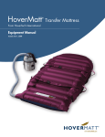
Once the HoverJack® air patient lift is inflated, the HoverMatt® transfer mattress can
be used with the same air supply unit for safe and easy lateral patient transfer to a
bed or stretcher.
The Purpose of the HoverJack® Technology
Consistent utilization of the HoverJack® air patient lift dramatically reduces back
injuries to staff that are caused by manually lifting patients who have fallen.
In addition, fewer staff members are required and the patient is lifted in a very
comfortable manner. When considering Fall Prevention guidelines, the HoverJack®
air patient lift is a critical component of a program that addresses the safety of the
patient and the caregiver if a patient does fall.
4
HJManual
Rev A
HOVERJACK®
USER MANUAL
Part Identification - Air Patient Lift
Transport Strap
Patient Safety Straps (2)
(DO NOT USE TO TRANSFER)
Transfer Handles (8)
Label Includes:
Model#, Serial# and
Instructions for use.
Red Deflate Cap and Valve
(4 Total)
Inflate Cap and Valve
(4 Total)
5
Rev A
HJManual
HOVERJACK®
USER MANUAL
Part Identification - Air Supply
Carrying Handle/
Attachment Hook
Power Cord
Strap
Hose Release Button
Control
Panel Label
Hose Nozzle
Power Cord
(US/UK/Euro/Aust)
Hose
Air Filter Cover
6
HJManual
Rev A
HOVERJACK®
USER MANUAL
Air Supply Keypad Functions
Adjustable Speed
Indication
Power Indication
Adjustable/
Pressure Setting
Transfer Speed High
Standby
Transfer Speed Low
The Adjustable Keypad function has four different settings. Pressing the
button once will result in the lowest inflation setting available. A second
press of the button increases the air pressure and rate of inflation. Pressing
the button a third time will again increase the rate of inflation. A fourth press
of the button results in the highest inflation rate and air pressure available
for HoverTech Accessories. The STANDBY button may be pressed at any time
to cease all air flow.
NOTE: The LED will indicate the inflation speed by the number of flashes
(i.e. two flashes equals the second inflation speed).
All of the settings in the Adjustable range are substantially lower than the
HoverMatt® and HoverJack® settings. The Adjustable function is not to be
used for transferring; it is only for use with HoverTech Accessories, which
require a lower pressure for slow inflation.
Standby: Used to stop inflation/air flow.
HoverMatt® 28 /34: For use with 28” & 34” HoverMatt® Air Transfer
Mattresses.
HoverMatt® 39 /50 & HoverJack®: For use with 39” & 50” HoverMatt® Air
Transfer Mattresses and 32” & 39” HoverJack® Air Patient Lifts.
7
Rev A
HJManual
HOVERJACK®
USER MANUAL
Instructions for Use
1. Place HoverJack® air patient lift on floor next to the patient, making sure the chamber with
Valve #4 is on the top and the chamber with Valve #1 is against the floor.
For safety, always use a minimum of two caregivers when operating the
HoverJack® air patient lift.
2. Make certain that all four red-capped deflation valves are capped tightly to maintain
inflation.
3. Log roll patient onto the deflated HoverJack® air patient lift and position patient with feet at
the valve end where indicated.
4. The patient can be placed on top of the HoverJack® air patient lift using the HoverMatt® Air
Transfer System. (See HoverMatt® instructions). If the HoverMatt® is used, make certain that
the HoverMatt® and patient are properly centered on the HoverJack® air patient lift. Always
deflate the HoverMatt® air transfer system prior to inflating the HoverJack® air patient lift.
Using buckles, secure patient safety straps around the patient.
5. Plug HoverTech International Air Supply power cord into an electrical outlet.
6. Hold hose against inlet Valve #1 of HoverJack® air patient lift.
7. Turn on Air Supply to the highest inflation level to begin inflation with valve #1.
HOVERJACK®
Use for sizes: 32 & 39
8. When fully inflated, remove hose. Valve will automatically close, keeping chamber inflated.
9. Using the same process, move to Valve #2, Valve #3 and Valve #4 in exact succession.
10.Turn off air supply by pressing standby button and cap valves.
11.Transfer from HoverJack® air patient lift onto adjacent surface using theHoverMatt® air
transfer system. Transfer without the HoverMatt® air transfer system may cause injury.
12.If it is necessary to lower patient down to the floor, release air by opening the uppermost
red deflate valve #4. When chamber #4 is fully deflated, move in succession downward to
fully deflate HoverJack® air patient lift. Caution: DO NOT RELEASE ALL CHAMBERS ALL AT
ONCE.
NEVER LEAVE PATIENT UNATTENDED ON INFLATED HOVERJACK® AIR
PATIENT LIFT.
8
HJManual
Rev A
HOVERJACK®
USER MANUAL
Product Specifications/Required Accessories
• Classification:
EQUIPMENT NOT SUITABLE FOR USE IN THE PRESENCE OF A FLAMMABLE
ANESTHETIC MIXTURE WITH AIR, OR WITH OXYGEN OR NITROUS OXIDE.
Not for use with Oxygen or Oxygen Enriched Atmospheres.
Type of Protection against electric shock: CLASS I EQUIPMENT
Degree of protection against electric shock: TYPE BF APPLIED PART
Protection against ingress of water: Ordinary (not protected).
Mode of operation: CONTINUOUS OPERATION
To remove supply mains, unplug equipment from wall
• Patient Weight Limit:
1,900lbs / 862kg
• Use Temperature:
50° to 104° F (10° to 40° C)
• Use Humidity:
10% to 70% Non-Condensing
• Storage/Shipping Temperature:
-40° to 176° F (-40° to 80° C)
• Storage/Shipping Humidity:
10% to 70% Non-Condensing
• Power Input:
120 V~, 60 Hz, 10 A (North American version)
230 V~, 50 Hz, 6 A (Australian Version)
• Air Supply Dimensions:
12.5 x 7 x 7 inches (31.75 x 17.8 x 17.8 cm)
• Air Supply Weight:
11 lbs. (5 kg)
• Air Supply Material:
Fire Retardant ABS/Stainless Steel
• Power Cord Length:
10 metres
9
Rev A
HJManual
HOVERJACK®
USER MANUAL
Product Specifications/Required Accessories
Material:
Topside Material: nylon oxford
Underside Material: Teflon® impregnated polyester
Construction:
RF-Welded
Width:
32” (81cm) or 39” (99 cm)
Length:
72” (183 cm)
Height:
30” (76 cm) Inflated (each chamber 7 1/2” [19 cm])
Required Accessory:
HoverTech International Air Supply
Part# HTAIR1200 (North American Version)
Part# HTAIR2300 (Australian Version)
All HoverTech International Products are Latex-Free.
For a full product listing go to www.statina.com.au
10
HJManual
Rev A
HOVERJACK®
USER MANUAL
Electromagnetic Compatibility Chart
For HTAIR-2300 ONLY
Guidance and Manufacturer’s Declaration – Electromagnetic Emissions
The HoverTech International Air Supply is intended for use in the electromagnetic environment
specified below. The customer or the user of the HoverTech International Air Supply should ensure
that it is used in such an environment.
Emissions Test
RF emissions
CISPR11
RF emissions
CISPR11
Harmonic emissions
IEC 61000-3-2
Voltage fluctuations/
flicker emissions
IEC-61000-3-3
Compliance
Group 1
Class A
Class A
Complies
Electromagnetic Environment Guidance
The HoverTech International Air Supply uses RF
energy only for its internal function. Therefore,
its RF emissions are very low and are not likely to
cause any interference in nearby electronic
equipment.
The HoverTech International Air Supply is suitable
for use in all establishments other than domestic
and those directly connected to the public lowvoltage power supply network that supplies
buildings used for domestic purposes.
11
Rev A
HJManual
HOVERJACK®
USER MANUAL
Electromagnetic Compatibility Chart
For HTAIR-2300 ONLY
Guidance and Manufacturer’s Declaration – Electromagnetic Immunity
The HoverTech International Air Supply is intended for use in the electromagnetic environment
specified below. The customer or the user of the HoverTech International Air Supply should ensure
that it is used in such an environment.
IEC 60601 Test
Level
± 6 kV contact
± 6 kV contact
± 8 kV air
± 8 kV air
Electrical fast
Transient/burst
± 2 kV for power
supply lines
± 2 kV for supply
mains
IEC 61000-4-4
± 1 kV for inputoutput lines
± 1 kV line(s) to
line(s)
± 1 kV for
input/output lines
± 1 kV line(s) to
line(s)
± 2 kV line(s) to
earth
< 5% UT
(> 95% dip in UT)
For 0,5 cycle
± 2 kV line(s) to
earth
< 5% UT
(> 95% dip in UT)
For 0,5 cycle
40% UT
(60% dip in UT)
For 5 cycles
40% UT
(60% dip in UT)
For 5 cycles
70% UT
(30% dip in UT)
For 25 cycles
70% UT
(30% dip in UT)
For 25 cycles
< 5% UT
(>95% dip in UT) for
5 seconds
3 A/m
< 5% UT
(>95% dip in UT) for
5 seconds
3 A/m
Immunity Test
Electrostatic
Discharge (ESD)
Compliance Level
IEC 61000-4-2
Surge
IEC 61000-4-5
Voltage dips, short
interruptions and
voltage variations
on power supply
input lines
IEC 61000-4-11
Power Frequency
(50/60 Hz)
magnetic field
Electromagnetic EnvironmentGuidance
Floors should be wood, concrete
or ceramic tile. If floors are
covered with synthetic material,
the relative humidity should be at
least 30%.
Mains power quality should be
that of a typical commercial or
hospital environment.
Mains power quality should be
that of a typical commercial or
hospital environment.
Mains power quality should be
that of a typical commercial or
hospital environment. If the user
of the HoverTech International Air
Supply requires continued
operation during mains
interruptions, it is recommended
that the HoverTech International
Air Supply be powered from an
uninterruptible power supply or a
battery.
Power frequency magnetic fields
should be at levels characteristic
of a typical commercial or
hospital environment.
IEC 61000-4-8
NOTE: UT is the AC mains voltage prior to application of the test level
12
HJManual
Rev A
HOVERJACK®
USER MANUAL
Electromagnetic Compatibility Chart
For HTAIR-2300 ONLY
Guidance and Manufacturer’s Declaration –Electromagnetic Immunity
The HoverTech International Air Supply is intended for use in the electromagnetic environment
specified below. The customer or the user of the HoverTech International Air Supply should ensure
that it is used in such an environment.
Immunity test
IEC 60601
test level
Compliance
level
Conducted RF IEC
61000-4-6
3 Vrms
150 kHz to
80 MHz
3V
Radiated RF IEC
61000-4-3
3 V/m
80 MHz to
2.5 GHz
3 V/m
Electromagnetic environment - guidance
Portable and mobile RF communications equipment
should be used no closer to any part of the
HoverTech International Air Supply, including cables,
than the recommended separation distance
calculated from the equation applicable to the
frequency of the transmitter
Recommended separation distance
d= 1.2 √P
d=1.2 √P 80 to 800 MHz
d=2.3 √P
800 MHz to 2.5 GHz
Where P is the maximum output power rating of the
transmitter in watts (W) according to the transmitter
manufacturer and d is the recommended separation
distance in meters (m).
Field strengths from fixed RF transmitters, as
determined by an electromagnetic site surveya,
should be less than the compliance level in each
frequency rangeb.
Interference may occur in the vicinity of equipment
marked with the following symbol:
NOTE 1: At 80 MHZ and 800 MHz, the higher frequency range applies.
NOTE 2: These guidelines may not apply in all situations. Electromagnetic propagation is affected by
absorption and reflection from structures, objects, and people.
a Field strengths from fixed transmitters, such as base stations for radio (cellular/cordless) telephones and land
mobile radios, amateur radio, AM and FM radio broadcast and TV broadcast cannot be predicted
theoretically with accuracy. To assess the electromagnetic environment due to fixed RF transmitters, and
electromagnetic site survey should be considered. If the measured field strength in the location in which the
device is used exceeds the applicable RF compliance level above, the device should be observed to verify
normal operation. If abnormal performance is observed, additional measures may be necessary, such as reorienting or relocating the device.
b Over the frequency range 150 kHz to 80 MHz, the field strengths should be less than 3 V/m.
13
Rev A
HJManual
HOVERJACK®
USER MANUAL
Electromagnetic Compatibility Chart
For
HTAIR-2300 ONLY
Recommended separation distances between portable and mobile RF
communications equipment and the HoverTech International Air Supply
The HoverTech International Air Supply is intended for use in an electromagnetic environment in
which radiated RF disturbances are controlled. The customer or the user of the HoverTech
International Air Supply can help prevent electromagnetic interference by maintaining a minimum
distance between portable and mobile RF communications equipment (transmitters) and the
HoverTech International Air Supply as recommended below, according to the maximum output power
of the communications equipment.
Rated maximum
output power of
transmitter
W
Separation distance according to frequency of transmitter
m
15 kHz to 80 MHz
d=[3.5/V1]√P
80 MHz to 800 MHz
d=[3.5/V1]√P
800 MHz to 2.5 GHz
d=[7/E1]√P
0.01
0.12
0.12
0.23
0.10
.38
.38
0.73
1
1.2
1.2
2.3
10
3.8
3.8
7.3
100
12
12
23
For transmitters rated at a maximum output power not listed above, the recommended separation
distance d in meters (m) can be estimated using the equation applicable to the frequency of the
transmitter, where P is the maximum output power rating of the transmitter in watts (W) according to
the transmitter manufacturer.
NOTE 1: At 80 MHz and 800 MHz, the separation distance for the higher frequency range applies.
NOTE 2: These guidelines may not apply in all situations. Electromagnetic propagation is affected by
absorption and reflection from structures, objects, and people.
14
HJManual
Rev A
HOVERJACK®
USER MANUAL
Cleaning & Maintenance
HoverJack® Air Patient Lift Cleaning Instructions
The HoverJack® air patient lift is constructed of nylon oxford. The HoverJack® air patient lift
may be covered with a sheet or other protective piece to help keep it clean. The HoverJack®
air patient lift can be wiped down with phenolic disinfectants, quaternaries, or other similar
type solutions as per hospital protocol for stretchers, or pads and/or bed mattresses.
Note: If using a protective sheet while moving a patient, make sure it doesn’t get caught
under the HoverJack® air patient lift. This could be a potential hazard.
*The HoverJack® air patient lift should not be laundered.
HoverJack® Air Patient Lift Maintenance Instructions
The HoverJack® air patient lift should be periodically inspected to ensure the following:
• All deflation valves are equipped with a red cap.
• The red caps are intact.
• All patient safety straps are attached to the HoverJack® air patient lift.
• All buckles are intact and operational.
• Pull handles are all attached to the HoverJack® air patient lift.
• Inflation valves are all self-sealing with no evident leakage.
• There are no punctures or tears in the HoverJack® air patient lift.
Air Supply Cleaning and Maintenance
The air supply has an air filter on either side of the motor. These filters can be accessed by
removing the small screws holding the filter cover in place. Filters should be cleaned by holding under warn running water. Allow to air dry. As preventive maintenance, filter cleaning
should be performed monthly.
The Air Supply can be cleaned by wiping down using a damp cloth with soap and water or
mild neutral detergent. Dry using a clean, dry cloth or disposable paper towels.
*Do not spray cleaners or liquids directly on the air supply.
NOTE: CHECK YOUR LOCAL/STATE/FEDERAL/INTERNATIONAL GUIDELINES BEFORE DISPOSAL.
15
Rev A
HJManual
HOVERJACK®
USER MANUAL
Frequently Asked Questions
1. Can you over inflate the HoverJack® air patient lift and cause it to burst?
No, not if you are using the HoverTech International Air Supply. The HoverJack® air
patient lift has been tested under conditions that would “over-inflate” using this air supply.
2. If you open the red-capped valves, does the HoverJack® air patient lift deflate very
quickly, causing it to be unstable and the patient to fall?
Yes, if you open the red-capped valves all at one time. However, opening the redcapped valves one at a time, beginning at the top chamber, permits the HoverJack® air patient
lift to deflate rather slowly, but steadily. The HoverJack® air patient lift remains stable when deflated properly.
3. If we want the HoverJack® air patient lift to lift the patient a moderate amount, do all of
the chambers have to be inflated for it to be stable?
No. The HoverJack® air patient lift is made to be stable regardless of how many
chambers are inflated. However, the chambers MUST be inflated consecutively from the
floor up. In other words, if you only want to inflate 3 chambers, you must inflate
chambers 1, 2 & 3.
4. Will the HoverJack® air patient lift raise a very heavy patient?
Yes. The HoverJack® air patient lift has been successfully tested under the weight of 1900
pounds / 862 kg. When lifting heavy patients, extra caution must be taken to center them
properly on the HoverJack® air patient lift.
16
HJManual
Rev A
HOVERJACK®
USER MANUAL
AIR SUPPLY
NO USER SERVICEABLE PARTS.
Only qualified service personnel shall perform repairs on the HoverTech
International Air Supply.
17
Rev A
HJManual
HOVERJACK®
USER MANUAL
Part Identification
Control Panel
Label
Dust Cover
Hose Attachment Snap
Air Filter Cover
Handle /
Attachment Hook
Air Filter
Metal Cover
Hose
Foot
Grounding Pin
Used for a Ground Continuity (Bond) Test.
Information Labels
Power Cord Clamp
Circuit Breakers
Bumpers
Power Cord
Strap
Power Cord
(US/UK/Euro/Aust)
18
HJManual
Rev A
HOVERJACK®
USER MANUAL
Power Cord / Clamp Replacement
19
Rev A
HJManual
HOVERJACK®
USER MANUAL
Handle Replacement
1. Remove the damaged handle by unscrewing the socket head screw from the barrel
nut using two 5/32” allen wrenches as shown.
2. Attach the new handle by reversing the process. When tightening the screw be sure
that the handle can rotate easily. The screw is treated with thread lock to secure it in
place.
Carrying Handle/
Attachment Hook
Barrel Nut
5/32” Allen
Wrench
Socket
Head Screw
5/32” Allen
Wrench
20
HJManual
Rev A
HOVERJACK®
USER MANUAL
Feet or Bumper Replacement
1. The feet and bumpers are held in place by a self-adhesive backing. Use a small, flat
bladed screwdriver to pry up an edge and gently remove the foot or bumper.
2. Clean surface thoroughly to remove any excess adhesive that may have been left
behind. Apply the new part by removing the backing material and position as shown.
Press firmly to ensure adhesion.
Bumper
Foot
21
Rev A
HJManual
HOVERJACK®
USER MANUAL
Hose Removal
1. Remove the damaged hose by lifting the dust cover slightly and unsnapping the hose
from the side of the unit as shown.
2. Push the release button at the top of the unit to remove the hose.
3. Attach the new hose by reversing the process.
Hose
Hose Release Button
Dust Cover
Hose Attachment Snap
22
HJManual
Rev A
HOVERJACK®
USER MANUAL
Air Filter and Air Filter Cover Replacement
To Remove Air Filter Covers
1. Disconnect hose from unit. (See page 22)
2. Remove the two phillips head screws on each side to detach the air filter covers.
3. Re-attach the new air filter covers and screws.
To Remove Air Filters
1. Follow the steps shown above to remove air
filter covers.
2. Remove air filters and replace.
3. Re-attach the air filter covers and screws.
* For air filter cleaning instructions please
refer to Page 15.
Air Filter
Air Filter Cover
23
Rev A
HJManual
HOVERJACK®
USER MANUAL
Dust Cover/Hose Attachment Snap Replacement
To Remove Dust Cover
1. Disconnect hose from unit. (See page 22)
2. Lift the cover “flap” to remove the 3 phillips head screws that attach the dust cover.
3. To replace dust cover, fold in the three flexible tabs. Then insert the screws one at a
time starting with the top middle followed by the sides.
To Remove Hose Attachment Snap
1. Disconnect hose from unit. (See page 22)
2. Remove the phillips head screw and snap.
3
2
Snap Replacement Detail
1
Dust Cover
24
HJManual
Rev A
HOVERJACK®
USER MANUAL
Metal Cover Replacement
1. Disconnect hose from unit. (See page 22)
2. Remove the two phillips head screws on each side to detach the air filter covers.
Remove the air filters.
3. Gently pull the damaged
cover apart to allow clearance to remove it.
4. Carefully re-insert the new metal cover.
Reassemble the two filters and filter covers.
5. Secure everything in place by reinserting
four screws.
Metal Cover
Air Filter
Air Filter Cover
25
Rev A
HJManual
HOVERJACK®
USER MANUAL
Cord Strap Replacement
1. Unsnap the strap and remove power cord.
2. Detach the damaged cord strap by removing the screw as shown.
3. Reattach strap by positioning in place and securing it with the screw provided.
Power Cord Strap
26
HJManual
Rev A
HOVERJACK®
USER MANUAL
Troubleshooting
27
Rev A
HJManual
HOVERJACK®
USER MANUAL
Component Parts List
28
HJManual
Rev A
HOVERJACK®
USER MANUAL
Warranty Statement
The HoverJack® air patient lift and the HoverTech International air supplies are warranted
to be free from defects in materials and workmanship for (1) one year. Warranty begins on
date of in-service by a Statina Healthcare representative or shipment date.
In the unlikely event that a problem arises as a result of a defect in materials or
workmanship, we will promptly repair your item or replace it if we feel that it cannot be
repaired – at our expense and discretion using current models or parts performing the
equivalent function – upon receipt of the original item to our repair department. You must
pre-notify Statina Healthcare Australia by phone (1300 365 404). Item is to be insured by you
against loss during transportation and must be shipped with transportation and/or broker
charges prepaid. Should any Hovertech International product be returned, which is not
covered under warranty, there will be a minimum $100 service charge plus shipping costs.
Lead-time for repairs is approx. 2 weeks. Please refer to the Return and Repairs section of
this Manual for return instructions.
This warranty is not an unconditional guarantee for the life of the product. Our warranty
does not cover product damage that may result from use contrary to Manufacturer’s
instructions or specifications, misuse, abuse, tampering, or damage due to mishandling.
Warranty specifically does not cover product damage that may result from using an air
supply that produces more than 3.5 psi to inflate the HoverJack® air patient lift.
Equipment that has been neglected, improperly maintained, repaired or altered by someone
other than an authorized representative of Manufacturer, or operated in anyway contrary to
the operating instructions, shall void this warranty.
This warranty does not cover normal “wear and tear”. Component parts, particularly any
optional equipment, valve caps, their attachments and cords, will show wear with use over
time and eventually may need to be refurbished or replaced. This normal type of wear is not
covered by our warranty, but we will provide prompt, high quality repair service and parts at
a nominal cost.
29
Rev A
HJManual
HOVERJACK®
USER MANUAL
Warranty Statement
Statina Healthcare’s liability under this warranty and on any claim of any kind for any
loss or damage arising out of, connected with, or resulting from the design, manufacture,
sale, delivery, installation, repair or operation of its products, whether in contract or tort,
including negligence, shall not exceed the purchase price paid for the product and upon
expiration of the applicable warranty period, all such liability terminates. The remedies which
this warranty provides are exclusive and Statina Healthcare Australia shall not be liable for any
incidental or consequential damages.
There are no warranties, express or implied, which extend beyond this warranty statement.
The provisions of these warranty clauses are in lieu of all other warranties, expressed or
implied, and of all other obligations or liabilities on Statina Healthcare' Australia''s part and
neither assumes nor authorizes any other person to assume for Statina Healthcare, any
other liability in connection with Manufacturer sale or lease of said products. Statina Healthcare
Australia makes no warranty of merchantability or fitness for a particular purpose. There
is no warranty that the goods will be fit for a particular purpose. By accepting the goods, the
buyer acknowledges that buyer has determined the goods are suitable for the buyer’s
purposes.
MANUFACTURER’S SPECIFICATIONS ARE SUBJECT TO CHANGE.
30
HJManual
Rev A
HOVERJACK®
USER MANUAL
Returns and Repairs
All products being returned to Statina Healthcare Australial must have a Return Goods
Authorization Number issued from the company. Please call 1300 365 404 for an RGA #.
Any products returned without the necessary RGA # may cause a delay in the repair time. If
the product is not covered under warranty, a minimum charge of $100 will be assessed for
each repair. Should a repair charge be assessed, Statina Healthcare will notify the
facility and a purchase order for the repair will need to be issued before the repair can be
completed. Lead-time for repairs is approximately 2 weeks. A fee of $50 will be assessed if
HoverJack® air patient lift are not properly cleaned for repair.
All products should be sent to:
Statina Healthcare Australia
3/30 Leighton Place.
Hornsby, NSW, 2077
Attn: Repair Dept./RGA #_______
Phone: 1300 365 404
Fax: 02-9482-2599
31
Rev A
HJManual
3/30 Leighton Place.
Hornsby, NSW, 2077
Phone: 1300 365 404
www.statina.com.au