1
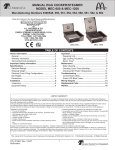
Manual 103-0039 REV. 08/14 Technical Manual for Rigid Lifelines Fall Protection Track SPECIFICATIONS SUBJECT TO CHANGE WITHOUT NOTICE ISO 9001 REGISTERED © RIGID LIFELINES® 2 TABLE OF CONTENTS Introduction to Fall Protection...................................................................................... 4 Rigid Lifelines Fall Protection Systems..........................................................................5 Specifying a Fall Protection System.............................................................................. 6 Plain Fall Arrest Track..................................................................................................7 Single Track Trussed Fall Arrest System.........................................................................7 Dual Trussed Fall Arrest Track...................................................................................... 8 Components...........................................................................................................7-14 Splices............................................................................................................. 8-10 Hangers..........................................................................................................11-13 End Stops.................................................................................................................14 Rotating Eyebolt Trolleys............................................................................................ 14 End Trucks............................................................................................................... 14 Aluminum Fall Arrest Track........................................................................................ 15 Fall Arrest Safety and Considerations.......................................................................... 16 Fall Arrest Component and System Installation Requirements....................................... 17 Installation Instructions............................................................................................. 17 Performance Testing of Fall Arrest Components and Systems........................................ 17 Inspection of Fall Arrest Systems................................................................................18 Lateral Bracing for Monorail....................................................................................... 19 FAC-480 Assembly Instructions.................................................................................. 20 Bar Joint Hanger Assembly.........................................................................................21 Sloped Hanger Assembly Instructions..........................................................................22 Beam Clamp - Chart.................................................................................................. 23 Annual Systems Inspection Checklist.......................................................................... 24 Annual Fold-Away Systems Inspection Checklist...........................................................25 Rigid Lifelines Warranty and Service Policy..................................................................28 3 INTRODUCTION TO FALL PROTECTION Unintentional falls are the leading cause of injury and the second most common cause of occupational related deaths in the United States. There are three methods of protecting workers from injury due to falls: 1. Eliminate the fall hazard. 2. Arrest the fall. 3. Restraint Arresting the fall may be done in a variety of ways, including guarding, nets, and personal fall protection systems. Personal Fall Protection systems consist of three main components; an anchorage, a body support, and the connecting means. This manual relates to the selection of a track system for dynamic protection of the worker. Harnesses and related equipment which work in conjunction with the track system require investigation of other sources. Each manufacturer’s equipment recommendation may vary from case to case and affect the forces put on the track to different degrees. A horizontal system is an anchoring track designed to be connected between two support points on the same level. This track, along with the trolley, serves as a mobile anchor point for the attachment of energy absorbing lanyards or self retracting lanyards. The purpose is to limit swing injuries by providing a continuous overhead support point as the worker moves horizontally along a work surface. The anchorage on a horizontal fall arrest system may be either static, such as an eye bolt, or dynamic, such as a lifeline or track system, which protects the worker from falling, yet provides the desired amount of mobility to accomplish the task to be performed. The total distance that a worker falls when attached to a horizontal type fall arrest system is equal to the fall distance of four components; the free fall distance, the amount of sag in the system, the deceleration distance of the shock absorbtion equipment the worker is using, and the stretching of the harness. Obviously the shorter the total fall distance, the less likely the worker will be injured. It is an industry accepted standard to include a 3’ safety factor for added clearance. Rigid Lifelines enclosed track systems ELIMINATE the sag distance component thereby lessening the overall fall distance. This allows the life saving lanyard and harness equipment to react faster and exert less force on the worker. This non sag action also lessens the likelihood of the worker colliding with an obstruction or lower grade level. 4 RIGID LIFELINES FALL PROTECTION SYSTEMS HANGER 900LB MAF PERSONAL ENERGY ABSORBING DEVICE RIGID HORIZONTAL LIFELINE CONNECTOR Rigid Lifelines fall arrest track systems have many distinctive advantages over wire rope systems. Rigid track design with less free fall distance should be taken into account since the stretch of the wire rope does not have to be figured into the equation. The worker can now be decelerated to a complete stop in a shorter distance, lowering the impact force on the body. This design also saves headroom since an allowance for sag is no longer necessary. This feature also allows for use of track in situations where there is a minimum of overhead room. Rotating eye trolleys provide smooth ergonomic movement within the track system and are not affected by side pull which can restrict the trolleys on a wire rope system, especially at the splices and hangers. The worker can now move freely from side to side under the track system, rather than be limited to the pathway directly below the wire rope. The rotating eye trolley allows 360º continuous movement eliminating tangling of the lanyard and harness. Side to side movement may be further enhanced through the use of double tracks and bridges known as traveling bridge systems. With the addition of track splices, the length is limitless. Splice design ensures a smooth transition at joints and hangers. Rigid truss design can be used to increase support centers to job and building requirements. Standard sizes are available to accomodate up to 58ft. support centers. All standard systems are designed for use with lanyards that limit the maximum arresting force to 900lbs. Special designs can be customized to virtually any distance. Utilizing track switches, turntables, transfer mechanisms and end trucks can make the scope and coverage of your fall arrest system virtually limitless. This is perfect for complete coverage of a facility such as; theatres, airplane hangers, bus depots, or anywhere overhead work is constant. All track, trolleys, cranes, and hangers are designed in accordance with A.N.S.I. Spec No. Z359.1-2007, OSHA Std. 1910.66, and OSHA Std. 1926.502 NOTE: If the same fall arrest system will be used to recover a fallen worker, a two man system must be specified. 5 SPECIFYING A FALL PROTECTION SYSTEM Fall Arrest Selection Thoughts 1. 2. 3. 4. How many workers will be using the system at one time? How will the system be supported? What type of lanyards and harnesses will be provided? Make sure you can move trolleys past support points without disengaging from the lanyards. 5. Evaluate whether the trolley will slide smoothly without causing a swing fall hazard. 6. If a worker falls off the edge of the work area, how many degrees off-vertical will the lanyard line be? 7. How will a fallen worker be rescued? Specifying a Fall Arrest System The following is an example of how to decide what fall arrest system will best suit the application at hand: The customer wants a one person system on 6 foot support centers with a 20 foot overall length: 1. Choose Fall Arrest Track: A. With 6'-0” support centers for a one person system we refer to the table on page 7. No. P500 track is selected. B. Choose the part number FAPT520C-1MAN from sheet 13 of the Rigid Lifelines Fall Arrest Track Price List. This will provide (3) 6-foot support center spaces, and the standard 12” overhangs on each end. 2. Choose Accessories: 2 End Stops No. 500ES 1 Personnel Trolley No. 524RI 4 Track Hangers, either drop rod or flush type 1 Label Kit Note that track splices are available to join multiple track sections together. Refer to pages 9-10 for track splices for track and splice plates for truss top tubes. 6 COMPONENTS Plain Fall Arrest Track 1. Profile is ASTM A-572 steel cold formed. 2. Enclosed track low profile keeps space requirements to a minimum. 3. Profile design ensures wheel protection and accurate alignment with minimum friction. 4. Minimum maintenance. “Self” cleaning profile. 5. Available in three sizes. Part Numbers: FA PT 5 XX (.XX) Decimal Feet Length Track Series Plain Track (if needed) Fall Arrest NOTES: 1. Maximum cantilever for one person on plain track is 2’ for 500* series track, and 3’ for 600*. 2. Maximum distance hanger to splice is 12”. 3. Refer to Page 8 for off-vertical loading. 4. Each section of track must have at least 2 hangers. TRACK SERIES A B 1 PERSON MAX S/C 2 PERSON MAX S/C PT500 2 9/16” 2 3/8” 10’-0” 8’-0” PT600 3 1/8” 2 15/16” 15’-0” 12’-6” * These lengths may be increased under certain circumstances. Consult with Rigid Lifelines engineering. Single Track Trussed Fall Arrest Systems 1. 2. 3. 4. Used for spanning greater distance between supports. Utilizes plain track profile for lower cord to insure conformity of components. Low profile keeps space requirements to a minimum. Combination of high strength to low weight ratio, helps reduce stress on structures. 5. Designed for one or two person systems. Part Numbers: 6. Available in six standard sizes, to accomodate up to 58’-0” spans. FA R 600- XX (.XX) 7. Custom design for any span greater than shown in catalogue. Decimal Feet Length Track Series Trussed Runway Trussed Single Track (Non-Passable) TRACK 1 USER 2 USERS SERIES MAX S/S MAX S/S (if needed) Fall Arrest A B C 520 20’ 17’ 10” 2” 2” 525 25’ 18’ 12 3/8” 2” 2” 530 30’ 25’ 14 3/8” 2 1/2” 520C 40’ 33’ 10 1/4” 2” 10” 525C 50’ 42’ 12 5/8” 2” 10” 530C 58’ 48’ 14 5/8” 2 1/2” 2 1/2” 12” NOTES: 1. Maximum cantilever on truss track is 48”. 2. Maximum distance hanger to splice is 48”. 3. Refer to Page 8 for off-vertical loading. C A LATERAL BRACING REQUIRED BY OTHERS. Rigid Lifelines recommends consulting a qualified professional architect or engineer in your local area to determine your building support adequacy. Considerations include your geographical region, snowfall, seismic loading, etc. Dimensions and weights are approximate and may change without notice.**NOTE: If the same fall arrest system will be used to recover a fallen worker, a two man system must be specified. 7 COMPONENTS (continued) Dual Trussed Fall Arrest Track 1. Profile is ASTM A-572 steel cold formed. 2. Enclosed track low profile keeps space requirements to a minimum. 3. Profile design ensures wheel protection and accurate alignment with minimum friction. 4. Minimum maintenance. “Self” cleaning profile. 5. Available in three standard sizes. 6. Custom design for spans greater than shown. Part Numbers: FA 2T520-XX (.XX) Decimal Feet (if needed) Length Track Series Trussed Fall Arrest NOTES: 1. Maximum cantilever is 48”. 2. Maximum distance hanger to splice is 48”. TRACK SERIES 2 USER MAX S/S A B C D 520DST 38’ 10” 2” 2” 7 1/8” 525DST 45’ 12 3/8” 2” 2” 7 1/8” 530DST 53’ 14 3/8” 2 1/2” 2 1/2” 7 5/8” LATERAL BRACING REQUIRED BY OTHERS. Rigid Lifelines recommends consulting a qualified professional architect or engineer in your local area to determine your building support adequacy. Considerations include your geographical region, snowfall, seismic loading, etc. Splices 1. Track splice joints are supplied complete with vertical and horizontal adjustment screws which facilitate precise alignment of the track sections at a joint. 2. When positioning splice joints it is important to insure that they are placed within the allowable distance from an adjacent support bracket for maximum loads. 3. Welded joints are possible, however they are not recommended as they inhibit the adjustments, future modification, or dismantling of a system. 4. In the case of truss trucks, splice plates are used to join the upper chords of the truss section. Maximum Off-Vertical Loading *Consult factory for loading exceeding 30º off-vertical. 30º Maximum* off-vertical loading Dimensions and weights are approximate and may change without notice. 8 COMPONENTS (continued) Splices (continued) Track Splice TRACK 500 600 700 500 DUAL TRACK WEIGHT LB. 5 8 1/2 17 7 1/2 DIM A (Fig. 1) 3 3/16” 3 15/16” 4 9/16” DIM B DIM C 7” 8” 2 15/16” 3 11/16” PART NO. 1503- 1603- 6 3/16” 10” 7’ 5 1/4” 2 15/16” 1703- 9-2420 If your system has more than one section length of fall arrest track, each additional section is installed in the same manner as the first, with the addition of a splice joint assembly. Plain track: Splice joints should be within 12” of a support bracket or hanger as shown in Fig. 1. Each section of track must have at least 2 hangers. Splice joints should be within 18”, 48” max, of a support bracket or hanger. The track splice joint is made from a sleeve with a total of eight set screws threaded into the top and both sides. Slide the sleeve over the end of the first runway track, then butt the second runway track against the first. Center the sleeve over the joint. The two center top set screws should be tightened slightly to push the tracks against the base of the sleeve so that the two bottom surfaces of the track are even. Adjust the side set screws so that the track slots are aligned and there is a smooth transition from one track to the other, see Fig. 2. Tighten all top set screws then side set screws for correct track alignment. (Fig. 2) 9 TRACK SERIES TORQUE SPECIFICATIONS 500 600 50 IN-LBS 60 IN-LBS EXCEEDING THESE TORQUE SPECIFICATIONS MAY CAUSE END TRUCKS TO BIND IN TRACK COMPONENTS (continued) Splices (continued) Track Splice Trussed fall arrest splice joints also include two splice plates and four, 1/2” bolts with nuts and lock washers. Install the splice plates to connect the ends of the truss tubes with the four through bolts provided. Torque through bolts to 50 FT. lbs., see Fig 3. TRACK 500 600 700 TRUSS TUBE SIZE 2” 2 1/2” 3” PLATES (2) BOLTS (4) SP-1 10-0218 LOCK NUTS (4) 10-0217 10-0206 13-0003 WEIGHT LB. 1 1/2 1 1/2 1 1/2 PART NO. SP-2 SP-25 SP-3 (Fig. 3) LATERAL BRACING REQUIRED BY OTHERS. Rigid Lifelines recommends consulting a qualified professional architect or engineer in your local area to determine your building support adequacy. Considerations include your geographical region, snowfall, seismic loading, etc. 10 COMPONENTS (continued) Hangers Plain Track Support Bracket 1. 2. 3. 4. Used to support plain track. Complete with adjustment screw. Cold formed to wrap around the track profile. Can be directly welded to overhead supports. TRACK 500 600 700 WEIGHT LB. 2 5 8 DIM A 3 1/4” 3 15/16” 4 1/2” DIM B 3 1/2” 4 1/2” 5” DIM C 2 15/16” 3 11/16” 5 1/4” DIM D 1/4” 5/16” 3/8” SETSCREW 5/16-18NC 3/8-16NC 1/2-13NC PART NO. Hangers Ceiling Support Bracket 1. Plain support bracket with mounting plate welded to top. 2. Bolted directly to overhead structure. 1504 1604 1704 TRACK 500 600 700 WEIGHT LB. 4 8 14 1/2 DIM A 6 11/16” 8 5/16” 10 1/4” DIM B 3 1/2” 4 1/2” 5” DIM C 2 15/16” 3 3/4” 5 5/16” DIM D 1/4” 3/8” 1/2” DIM E 4 13/16” SETSCREW 5/16-18NC PART NO. 502 SLOTTED HOLES 11/16 x 1 1/8” 3/8-16NC 1/2-13NC 602 702 TRACK 500 600 WEIGHT LB. 3 7 DIM A 2 9/16” 3 1/8” DIM B 3 1/2” 4 1/2” DIM C 3 15/16” 5” DIM D 1/4” 3/8” MOUNTING HOLES 11/16” 7/8” SETSCREW 5/16-18 3/8-16 PART NO. 501 601 Hangers Side Support Bracket 1. Furnished to allow mounting of plain track to side of support structure. 2. Furnished complete with bolts, nuts, and lockwashers. HOLES FOR MOUNTING BOLT DIM E E MOUNTING HOLES SETSCREW 11 COMPONENTS (continued) Hangers Drop Rod Support Bracket 1. Used to support plain track when supplied with drop rods. 2. Fabricated from plain support bracket and steel tubing. 3. Top hole pre-drilled for appropriate drop rod. TRACK 500 600 700 WEIGHT LB. 3 6 1/2 9 1/2 DIM A 3 1/4” 3 15/16” 4 1/2” DIM B 3 1/2” 4 1/2” 5” DIM C 2 15/16” 3 11/16” 5 1/4” DIM D 1/4” 5/16” 3/8” DIM E 4 15/16” 6 11/16” 8 1/4” HANGER ROD PART NO. 5/8”Ø 500HB 3/4”Ø 600HB 700HB Hangers Truss Track Drop Rod Hanger 1. Used to support truss track when supplied with drop rods. 2. Fabricated from structural steel. 3. Complete with proper nuts, bolts, lockwashers, and spacers. TRUSS STYLE TRACK R500 R525 R530 TRUSS TUBE 2” 2 1/2” TIE ROD DIA. or BOLT DIA. 5/8” 5/8” WEIGHT LB. 4 1/2 5 PART NO. FAHTB2 FAHTB25 Hangers Truss Track Flush Clamp 1. Furnished for direct clamping to overhead steel. 2. Complete with nuts, bolts, lockwashers, lindapters, and spacers. 3. Overhead beam size must be specified when ordering. TRUSS STYLE TRACK R520/R520C R525/R525C R530/R530C WEIGHT LB. 14 14 PART NO. FAK-20 FAK-25 K-H-20 through K-H-30 maximum flange width 6” K-H-35 and K-H-40 maximum flange width 8.5” 12 COMPONENTS (continued) Hangers Adjustable Beam Clamp 1. Utilized to attach to overhead steel when using drop rod hangers. 2. Furnished in two sizes: C480 - Fits beams with 2-1/4” to 8” flange width, 7/16” max. thickness. C482 - Fits beams with 4” to 10” flange width, 1/2” max. thickness. TRACK PROFILE CLAMPS REQD. HANGER ROD DIA PART NO. WEIGHT LB. PART NO. WEIGHT LB. 500 600 700 900 1 1 1 2 5/8” 3/4” FAC-480 5 3/4 C-482 20 Hangers Hanger Kit Plain Track 1. Standard kit furnished with C480 adjustable beam clamp, drop rod support bracket, and 12” rod. TRACK 500 PART NO. 600 700 FAK-CMP-500 FAK-CMP-600 FAK-CMP-700 WEIGHT LB. 11 17 23 Hangers Hanger Kit Truss Track 1. Standard kit furnished with C480 adjustable beam clamp, drop rod support bracket, and 12” rod. TRUSS STYLE TRACK R520/R520C R525/R525C R530/R530C WEIGHT LB. 12 27 PART NO. FAK-CMT-500 FAK-CMT-530 LATERAL BRACING REQUIRED BY OTHERS. Rigid Lifelines recommends consulting a qualified professional architect or engineer in your local area to determine your building support adequacy. Considerations include your geographical region, snowfall, seismic loading, etc. 13 COMPONENTS (continued) End Stops 1. Must be used at ends of all tracks to prevent trolley from leaving track profile when in use. 2. Bolt through connection supplied with rubber bumper, bolt, nut, and lockwasher. 3. May be used as intermediate stop to prevent workers from entering same area of track system. TRACK 500 600 700 WEIGHT LB. 1/2 1/2 1/2 DIM A 1/2” 1/2” 1/2” DIM B 2” 2 5/8” 3” PART NO. FA500ES FA600ES FA700ES NOTE: Must be used on ends of ALL tracks. Rotating Eye Trolley 1. All steel body. 2. Plastic wheels furnished as standard, equipped with anti-friction ball bearings for smooth and effortless movement. Steel wheels optional at no charge. 3. Rotating eye travels full 360º to allow complete freedom of movement without concern for twisting of lanyard or harness. TRACK SERIES TROLLEY 500 SERIES C/DST FA525-AT 5 1/4” 2 9/16” 5 1/8” 1 1/2” 600 SERIES FA624RI 5 5/16” 2 15/16” 6 1/4” 1 1/2” 700 SERIES FA724RI 5 3/8” 1 1/2” A B 4 1/8” C D 8 7/8” End Trucks 1. Used to make crane bridge where lateral travel is desired. 2. All steel body. 3. Plastic wheels standard, steel are available. 14 TRACK 500 600 700 CAPACITY 500 1000 2000 WEIGHT LB. 14 24 48 DIM A 3/8” 1/2” 5/8” DIM B 1’-5 11/16” 1’-7 11/16” 1’-11 5/8” DIM C 3 9/16” 4 3/16” 5 5/8” DIM D 7” 8” 10” PART NO. 1554SL 1654SL 1754SL ALUMINUM FALL ARREST TRACK ALU-TRACK® with plain splice and standard hanger. ALU-TRACK® 1 MAN** 2 MAN MAX S/C MAX S/C TRACK SERIES A 306 6” 11’-6” 9’-6” 308 8” 20’ 17’ REINFORCED ALU-TRACK® 1 MAN** 2 MAN MAX S/C MAX S/C TRACK SERIES A 306 12.5” 30’ 26’ LATERAL BRACING REQUIRED BY OTHERS. Rigid Lifelines recommends consulting a qualified professional architect or engineer in your local area to determine your building support adequacy. Considerations include your geographical region, snowfall, seismic loading, etc. ALU-TRACK® Hoist Trolley B A C D TRACK SERIES TROLLEY A B C D 6” ALU AT-HTK6-01 3” 6” 6” 8 1/16” 8” ALU AT-HTK8-01 3 3/4” 7 7/8” 8” 10 9/16” ALU-TRACK® Hangers TRACK SPLICE HANGER KIT 306 308 A B AT-HK6-01-1.00 AT-HK6-01-2.00 AT-HK8-01-1.00 AT-HK8-01-2.00 A 10-3/8” 263.5MM 1’-10 3/8” 568.5MM 10 1/4” 260MM 1’-10 1/4” 565MM B 1’-4 3/8” 416MM 2’-4 3/8” 721MM 1’-6 1/4” 463.5MM 2’-6 1/4” 921MM LATERAL BRACING REQUIRED BY OTHERS. Rigid Lifelines recommends consulting a qualified professional architect or engineer in your local area to determine your building support adequacy. Considerations include your geographical region, snowfall, seismic loading, etc. Dimensions and weights are approximate and may change without notice.**NOTE: If the same fall arrest system will be used to recover a fallen worker, a two man system must be specified. 15 FALL ARREST SAFETY AND CONSIDERATIONS Fall Arrest Safety 1. Remove systems and components from service IMMEDIATELY if they have been subjected to fall impact until inspected by a competent person and deemed undamaged and suitable for use. 2. Promptly rescue employees in the event of a fall, or assure that they are able to rescue themselves. 3. Inspect systems prior to each use for wear, damage, and other deterioration; and remove defective components. 4. Do NOT attach fall arrest systems to guard rail systems or hoists. 5. Do NOT attach fall arrest systems to crane bridges unless specifically designed for such use by a qualified person. 6. Every fall arrest system should have a rescue plan to recover fallen workers. If the same fall arrest system will be used to recover a fallen worker, a two man system must be specified. Fall Arrest Considerations Anyone working over a height of 4 ft. or more above a lower level with an unprotected side or edge in general industry shall be protected from falling. Anchorages used for attachment of personal fall arrest equipment shall be independent and capable of supporting at least 5000 pounds per employee attached, or designed, installed and used as part of a complete fall arrest system which maintains a safety factor of two (2) and under the supervision of a qualified person. Per OSHA 1926.500, Subpart M, “Anchorages used for attachment of personal fall arrest equipment shall be independent and capable of supporting at least 5000 pounds per employee attached, or designed installed and used as part of a complete fall arrest system which maintains a safety factor of two (2) and under the supervision of a qualified person. Personal fall arrest systems when stopping a fall shall: 1. 2. 3. Be rigged so that an employee can neither free fall more than 6 feet nor contact any lower level. Bring an employee to a complete stop and limit maximum deceleration distance an employee travels to 3.5 feet. Have sufficient strength to withstand twice the potential impact of an employee free falling a distance of six (6) feet or the free fall distance permitted by the system, whichever is less. Note: Consult factory for custom design if maximum arresting force exceeds 900 lb. Personal fall arrest systems shall not be attached to guardrail systems. Systems shall be inspected prior to each use for wear, damage and other deterioration. If the system is to be used by an employee having a combined person and tool weight of more than 310 pounds, then the system must be appropriately modified. Personal Fall Arrest Systems and components subjected to impact loading shall be immediately removed from service and shall not be used again for employee protection until inspected and determined to by a competent person to be undamaged and suitable for reuse. Check bolts for tightness annually, or more frequently if the system is subjected to extreme environments or severe service. 16 FALL ARREST COMPONENT AND SYSTEM INSTALLATION REQUIREMENTS Engineered Fall Arrest components and standard systems displayed in Rigid Lifelines sales literature are pre-engineered for vertical loading applications up to a maximum of 30 degrees offvertical and comply with all regulations as defined by ANSI Z359.1 and OSHA 1926.502 for engineered components. Engineered Fall Arrest custom systems are application specific, and take into consideration the actual, site specific, use of the system. This includes defined dimensions of height and cantilever, and any lateral loading (non-vertical loading) that may exist. When Rigid Lifelines Fall Arrest components are ordered individually, each component must be employed and maintained in accordance with all ANSI and OSHA regulations. INSTALLATION INSTRUCTIONS Install components as defined in this manual and in accordance with ANSI and OSHA regulations. If the system is a standard engineered Fall Arrest system, install the system(s) as defined on the provided assembly drawings included in the (reference) Installation and Maintenance Manuals, P/N 103-0010, 103-0011, or 103-0033. Installation and Maintenance Manuals, P/N 103-0010, 103-0011, or 103-0033 are crane installation manuals and provided for installation guidance reference only. If the system has been custom engineered as custom system by Rigid Lifelines, install the system(s) as defined on the provided custom assembly drawing. ! WARNING r NOTE: Rigid Lifelines fall arrest components are similar to crane designs, but may never be used as a crane. Never use a Rigid Lifelines Fall Arrest component or system as a crane or to lift objects, unless specifically engineered by Rigid Lifelines to do so. PERFORMANCE TESTING OF FALL ARREST COMPONENTS AND SYSTEMS Rigid Lifelines recommends following the ANSI requirements for dynamic performance testing of all Rigid Lifelines fall arrest components and systems. The dynamic performance test, as defined by ANSI Z359.1-2007 consists of a 220 lb test weight dropped for a total 6-foot free fall before a 900 lb MAF (maximum arresting force) lanyard engages to decelerate the load. A two-man system will use two separate weights (using one 900 MAF lanyard per weight), a three-man system will use three separate weights, and so on. ANSI standards are available at www.ansi.org 17 INSPECTION OF FALL ARREST SYSTEMS Before Each Use: • Operators should visually inspect the fall arrest system before each use. Annual Inspection: 1. Inspect all bolts for tightness. 2. Inspect all components for cracks, bends. 3. Inspect any pivot bolts or pivot eye bolts for bent shanks or bent shafts. If shaft is bent more than .010” replace. Replace any components if threads are deteriorated, or if there are any imperfections. 4. Inspect track flanges. If lower flanges are bent more than 5 degrees, replace track. If flange thickness has decreased more than 10% through wear, erosion, or corrosion, replace. Inspection After a Fall: Rigid Lifelines components must be inspected by a competent person (as defined by ANSI & OSHA) in the event of a fall. If the Rigid Lifelines provided components pass inspection all Rigid Lifelines components can be immediately placed back into service. A competent person should inspect for the following: 1. 2. 3. 4. Inspect all components for straightness. Replace any bent components. Inspect all components for cracks. Inspect all bolts for tightness. Inspect any pivot bolts or pivot eye bolts for bent shanks or bent shafts. If shaft is bent more than .010” replace. Replace any components if threads are deteriorated, or if there are any imperfections. 5. Inspect track flanges. If lower flanges are bent more than 5 degrees replace track. 18 19 LATERAL BRACING FOR MONORAIL FAC-480 ASSEMBLY INSTRUCTIONS 20 BAR JOINT HANGER ASSEMBLY RIGID LIFELINES IS NOT RESPONSIBLE FOR ENGINEERING, DESIGN, VALIDATION, OR QUALITY OF SUPPORT STRUCTURE. 21 SLOPED HANGER Assembly Instructions: HANGER ROD NUT (5/8” OR 3/4”) TORQUE NUT TO NUT TO A VALUE OF 112 FT-LB. LOCK NUT MUST GO HERE 1. 2. 3. 4. 5. 6. 7. 8. 9. 10. NOTE: MAX BEAM SLOPE 19º, (3” PER FOOT) RIGID LIFELINES IS NOT RESPONSIBLE FOR ENGINEERING, DESIGN, VALIDATION OR QUALITY OF SUPPORT STRUCTURE. 1. Nuts must be torqued to prevent rod from turning out. 2. Clips must be positioned such that they seat fully in cutout, with the bolt as close as possible to the edge of the beam flange. 3. Position clips such that they are an equal number of cutouts from the center. 4. Tighten nut 6 to pull clamp channel tightly against beam. 22 (Ref) Existing Building Structure (1) Beam Clamp Channel (2) Beam Clamp Clip (Ref) Hanger Rod (5/8” or 3/4”) (2) 5/8”-11 NC X 4 1/2”, GR 5 (2 Ref) 5/8”-11 NC Hex Nuts (2) 5/8” Flat Washer (1) Spherical Washer (5/8” or 3/4”) (3) Lock Nut (5/8” or 3/4”) (2) Bevel Washer BEAM CLAMP - CHART (OR NO DOT) 23 *Download and print blank checklists from the Literature link at rigidlifelines.com Rigid Lifelines Annual Fall Protection Systems Inspection Checklist Inspector Name: ___________________ Date: ____________________ System Number: ___________________ Model: ____________________ 24 Rigid Lifelines Fold-Away Fall Protection Systems Inspection Checklist Inspector Name: ___________________ Date: ____________________ System Number: ___________________ Model: ____________________ Inspection Result (3) Inspection Point Pass 1) Test the operation of the support jibs and verify the jibs and connector pivots rotate freely. 2) Check the support jibs for excessive bearing wear. 3) Check the support jibs for properly installed and tightened pivot bolts. 4) Check the support jibs for loose or missing fasteners. 5) Check the jib connector pivots for bent or broken parts, or bent or broken welds. 6) Check support structure for stability. *Download and print blank checklists from the Literature link at rigidlifelines.com 25 Fail Rigid Lifelines Fall Protection Systems Inspection Notes 26 Rigid Lifelines Fall Protection Systems Inspection Notes 27 Rigid Lifelines 730 Hemlock Road Suite 104 Morgantown, PA 19543 Toll Free: (844) 467-4443 Local: (610) 286-8030 Fax: (610) 286-6408 RigidLifelines.com TEN-YEAR EQUIPMENT WARRANTY Rigid Lifelines warrants the engineered track equipment, wearable end truck wheels, and Anchor Trolley™ wheels and teeth to be free from defects in material and workmanship for a period of ten (10) years commencing on the date of installation. TWO-YEAR EQUIPMENT WARRANTY Rigid Lifelines warrants XSPlatforms Fall Protection components to be free from defects in material and workmanship for a period of two (2) years commencing from the date of installation. ONE-YEAR EQUIPMENT WARRANTY Rigid Lifelines warrants the motorized products and drive components to be free from defects in material and workmanship for a period of one (1) year, commencing on the date of shipment to the first retail purchaser (“Purchaser”). Rigid Lifelines warrants all Rigid Lifelines fall protection soft goods, devices, connectors, and accessories to be free from defects in material and workmanship for a period of one (1) year, commencing on the date of shipment to the first retail purchaser (“Purchaser”). Rigid Lifelines is dedicated to offering superior service and quality products to all of our customers. If you would like to contact a customer service representative, please call the following number: 1 (844) 467-4443. We will be happy to assist you in any way that we can. These warranties do not extend to equipment which has been subject to misuse, use in excess of rated capacity, negligent operation, use beyond Rigid Lifelines published service factors, improper installation or maintenance, adverse environments, and does not apply to any equipment which has been repaired or altered without Rigid Lifelines written authorization. This warranty is void for any product that is designed to deform or absorb energy during a fall event and needs to be replaced after a fall event has occurred. Written notice of any claimed defect must be given to Rigid Lifelines within thirty (30) days after such defect is discovered. Rigid Lifelines obligation, and Purchaser’s sole remedy under this warranty is limited to, at Rigid Lifelines discretion, the replacement or repair of the equipment at Rigid Lifelines factory or at a location approved by Rigid Lifelines. THIS WARRANTY IS EXPRESSLY IN LIEU OF ALL OTHER WARRANTIES WHATSOEVER WHETHER EXPRESS, IMPLIED, OR STATUTORY. SELLER MAKES NO WARRANTY AS TO THE MERCHANTABILITY OR FITNESS FOR A PARTICULAR PURPOSE OF THE EQUIPMENT AND MAKES NO OTHER WARRANTY, EITHER EXPRESS OR IMPLIED. Rigid Lifelines shall not be liable, under any circumstances, for any indirect, special, or consequential damages including (but not limited to): lost profits, increased operating costs, or loss of production. This warranty shall not extend to damages including (but not limited to): lost profits, increased operating costs, or loss of production. This warranty shall not extend to any components or accessories not manufactured by Rigid Lifelines (example: casters), with the exception of the components, systems, or accessories involved with XSPlatforms, and purchaser’s remedy for such components and accessories shall be determined by the terms and conditions of any warranty provided by the manufacturer of such components and accessories. SERVICE POLICY 1. Obtain as much information as possible concerning the problem through personal observation by yourself or other authorized personnel familiar with the job and equipment: include model, serial and/or part numbers, voltages, speeds and any other special identifying features. Be prepared to discuss the situation in detail. 2. All authorized labor charges will be based on straight time. Hourly rates, estimated man hours, and not to exceed total dollar amount required for corrections are to be agreed upon before authorization is given. There will be no allowances for overtime except in dire emergencies and then only with prior approval. 3. A verbal agreement may be reached immediately on both the method of correction and the approximate cost. A warranty authorization number will be assigned for the specific incident. A confirming written authorization will be forwarded to the distributor. 4. The distributor must send an itemized invoice, showing our release number or invoice number and warranty authorization number after authorized corrections have been made. A credit memo will be issued by accounting after the invoice has been received and approved. Warranty charges ARE NOT to be deducted from outstanding open account invoices under any circumstances. 5. Any field corrections made prior to an authorization by Rigid Lifelines will not be accepted as a warranty charge or the responsibility of Rigid Lifelines. Any modification to the equipment made without the prior approval of the seller will void all warranties. A verbal authorization for modification may be obtained, in which event a warranty authorization number will be assigned for the specific modification. A confirming written authorization will be forwarded to the distributor. 28 ©2014. All rights reserved. All specifications and product designs subject to change without notice. All trademarks are the sole property of their respective owners. RLL-FPTV1