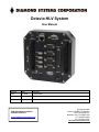
1
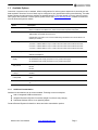
init
Octavio-HLV System
User Manual
Revision
Date
Comment
v1.00
11/24/09
Initial Release
FOR TECHNICAL SUPPORT
PLEASE CONTACT:
[email protected]
Copyright 2009
Diamond Systems Corporation
1255 Terra Bella Ave.
Mountain View, CA 94043 USA
Tel 1-650-810-2500
Fax 1-650-810-2525
www.diamondsystems.com
TABLE OF CONTENTS
1
Introduction ....................................................................................................................................................... 5
1.1
Functional Specifications ................................................................................................................................ 5
1.2
Physical Specifications ................................................................................................................................... 6
1.3
Available Options ............................................................................................................................................ 7
2 Functional Overview......................................................................................................................................... 8
2.2
Octavio-HLV Functional Block Diagram ......................................................................................................... 9
2.3
Helios SBC Functional Block Diagram ......................................................................................................... 10
2.4
External Connector Summary ...................................................................................................................... 11
3 Getting Started ................................................................................................................................................ 13
3.1
System Setup ............................................................................................................................................... 13
4 External Connectors....................................................................................................................................... 15
4.1
Serial Ports 1, 2, 3, 4 .................................................................................................................................... 15
4.2
Serial Ports 5, 6 (optional) ............................................................................................................................ 15
4.3
Keyboard, Mouse ......................................................................................................................................... 16
4.4
USB0, USB1, USB2, USB3 .......................................................................................................................... 17
4.5
Power In ....................................................................................................................................................... 17
4.6
VGA .............................................................................................................................................................. 18
4.7
Ethernet ........................................................................................................................................................ 19
4.8
Digital I/O Port .............................................................................................................................................. 20
4.9
Data Acquisition I/O Connector .................................................................................................................... 21
4.10
Expansion I/O (optional) ........................................................................................................................... 22
5 Internal Connectors ........................................................................................................................................ 23
5.1
SBC Interface Connectors ............................................................................................................................ 23
5.2
Expansion Board Interface Connectors ........................................................................................................ 23
6 Internal Configuration Jumpers .................................................................................................................... 27
6.1
Jumper Summary ......................................................................................................................................... 27
6.2
Data Acquisition Interrupt Configuration (J21) ............................................................................................. 27
6.3
RS-232 / RS-422 / RS-485 Configuration (J25, J26) ................................................................................... 28
7 Power Considerations .................................................................................................................................... 28
7.1
Power Switch Usage .................................................................................................................................... 28
7.2
Direct SBC Power vs. Power Via DC/DC Supply Board .............................................................................. 29
8 Additional Internal Expansion ....................................................................................................................... 30
9 End Cap Dimensions ...................................................................................................................................... 31
10 Technical Support .......................................................................................................................................... 31
Octavio-HLV User Manual
www.diamondsystems.com
Page 2
IMPORTANT SAFE HANDLING INFORMATION
WARNING!
ESD-Sensitive Electronic Equipment
Observe ESD-safe handling procedures when working with this product.
Always use this product in a properly grounded work area and wear
appropriate ESD-preventive clothing and/or accessories.
Always store this product in ESD-protective packaging when not in use.
Safe Handling Precautions
The Octavio unit contains a high number of I/O connectors with connection to sensitive electronic components. This
creates many opportunities for accidental damage during handling, installation and connection to other equipment.
The list here describes common causes of failure found on boards returned to Diamond Systems for repair. This
information is provided as a source of advice to help you prevent damaging your Diamond (or any vendor’s)
embedded computer boards.
ESD damage – This type of damage is usually almost impossible to detect, because there is no visual sign of
failure or damage. The symptom is that the board eventually simply stops working, because some component
becomes defective. Usually the failure can be identified and the chip can be replaced.
To prevent ESD damage, always follow proper ESD-prevention practices when handling computer boards.
Damage during handling or storage – On some boards we have noticed physical damage from mishandling. A
common observation is that a screwdriver slipped while installing the board, causing a gouge in the PCB surface
and cutting signal traces or damaging components.
Another common observation is damaged board corners, indicating the board was dropped. This may or may not
cause damage to the circuitry, depending on what is near the corner. Most of our boards are designed with at least
25 mils clearance between the board edge and any component pad, and ground / power planes are at least 20 mils
from the edge to avoid possible shorting from this type of damage. However these design rules are not sufficient to
prevent damage in all situations.
A third cause of failure is when a metal screwdriver tip slips, or a screw drops onto the board while it is powered on,
causing a short between a power pin and a signal pin on a component. This can cause overvoltage / power supply
problems described below. To avoid this type of failure, only perform assembly operations when the system is
powered off.
Power supply wired backwards – Our power supplies and boards are not designed to withstand a reverse power
supply connection. This will destroy each IC that is connected to the power supply (i.e. almost all ICs). In this case,
the board will most likely cannot be repaired and must be replaced. A chip destroyed by reverse power or by
excessive power will often have a visible hole on the top or show some deformation on the top surface due to
vaporization inside the package. Check twice before applying power!
Board not installed properly in PC/104 stack – A common error is to install a PC/104 board accidentally shifted by 1
row or 1 column. If the board is installed incorrectly, it is possible for power and ground signals on the bus to make
contact with the wrong pins on the board, which can damage the board. For example, this can damage components
attached to the data bus, because it puts the 12V power supply lines directly on data bus lines.
Overvoltage on analog input – If a voltage applied to an analog input exceeds the design specification of the board,
the input multiplexor and/or parts behind it can be damaged. Most of our boards will withstand an erroneous
connection of up to 35V on the analog inputs, even when the board is powered off, but not all boards, and not in
all conditions.
Octavio-HLV User Manual
www.diamondsystems.com
Page 3
Overvoltage on analog output – If an analog output is accidentally connected to another output signal or a power
supply voltage, the output can be damaged. On most of our boards, a short circuit to ground on an analog output
will not cause trouble.
Overvoltage on digital I/O line – If a digital I/O signal is connected to a voltage above the maximum specified
voltage, the digital circuitry can be damaged. On most of our boards the acceptable range of voltages connected to
digital I/O signals is 0-5V, and they can withstand about 0.5V beyond that (-0.5 to 5.5V) before being damaged.
However logic signals at 12V and even 24V are common, and if one of these is connected to a 5V logic chip, the
chip will be damaged, and the damage could even extend past that chip to others in the circuit.
Bent connector pins – This type of problem is often only a cosmetic issue and is easily fixed by bending the pins
back to their proper shape one at a time with needle-nose pliers. The most common cause of bent connector pins is
when a PC/104 board is pulled off the stack by rocking it back and forth left to right, from one end of the connector
to the other. As the board is rocked back and forth it pulls out suddenly, and the pins at the end get bent
significantly. The same situation can occur when pulling a ribbon cable off of a pin header. If the pins are bent too
severely, bending them back can cause them to weaken unacceptably or even break, and the connector must be
replaced.
Octavio-HLV User Manual
www.diamondsystems.com
Page 4
1 INTRODUCTION
Octavio-HLV embedded application servers are compact, rugged systems aimed at a wide variety of data
acquisition and control applications. The systems are based Diamond’s field-proven Helios PC/104 single board
computer, which combines an 800MHz Vortex86DX CPU and integrated peripheral interface functions along with
Diamond’s industry-leading high-accuracy data acquisition circuitry.
Octavio-HLV comes with 256MB of soldered DRAM for increased resistance to shock and vibration. It also has a
128MB or 1GB solid state IDE flashdisk pre-loaded with Linux 2.6.23 and Diamond’s Universal Driver data
acquisition programming software, leaving ample room for your application on the flashdisk.
Standard system I/O includes VGA graphics, a 10/100Base-T Ethernet interface, four USB 2.0 ports, two RS-232
serial ports, two RS-232/422/485 ports, and PS/2 keyboard and mouse interfaces.
When ordered with its optional data acquisition (DAQ) subsystem, Octavio-HLV provides 16 16-bit A/D inputs with
100KHz sample rate, 4 12-bit D/A outputs, 40 digital I/O lines, and 2 counter/timers. Multi-range autocalibration on
both A/D and D/A ensures maximum accuracy over time and temperature.
The Octavio-HLV enclosure is designed to eliminate most internal cables, resulting in enhanced ruggedness and
reliability in both fixed and mobile environments.
All of the system’s standard interfaces are accessible on the front of the enclosure via industry standard
connectors, which are mounted on a Panel I/O Board. The Panel I/O Board also accommodates I/O from selected
PC/104 add-on modules. The system is highly shock and vibration tolerant, and can operate fanless over -40°C to
+85°C.
1.1
Functional Specifications
1.1.1
System Core Functions
Based on Diamond Systems Helios single-board computer (SBC)
o Processor: 800MHz Vortex86DX CPU
o System Memory: 256MB soldered DRAM
Display type: VGA CRT; up to 1280 x 1024 resolution
USB ports: four USB 2.0
Serial ports
o Standard: two RS-232/422/485; two RS-232-only
o Option: additional two RS-232/422/485 (requires 3-inch or taller system height)
Networking: 10/100Base-T Ethernet
16 digital I/O lines
Mass storage: integrated 128MB or 1GB IDE flashdisk
Keyboard/mouse: PS/2 or USB
Operating system: Linux 2.6.23
System software: Universal Driver 6.02
1.1.2
Data Acquisition Subsystem (on select models)
Analog Inputs
o Inputs: 16 single-ended or 8 differential, user selectable
o 16 bits A/D resolution: 16 bits
o
Input ranges: ±10V, ±5V, ±2.5V, ±1.25V, 0‐10V, :0‐5V, 0‐2.5V programmable
o
o
o
o
Max sample rate 100KHz
Protection: ±35V on any analog input without damage
Nonlinearity: ±3LSB, no missing codes
Onboard FIFO
Octavio-HLV User Manual
www.diamondsystems.com
Page 5
o
o
o
2048 samples, programmable threshold
A/D and D/A calibration
Autocalibration with software support
Analog Outputs
o Number of outputs: 4, 12-bit resolution
o Output ranges: ±5V, ±10V, 0-5V, 0-10V
o Output current: ±5mA max per channel
o Settling time: 10μS max to 0.012%
o Relative accuracy: ±2 LSB
o Nonlinearity: ±2 LSB, monotonic
Digital I/O
o Number of I/O lines: 40 lines
o Input voltage: Logic 0: 0.5V min, 0.8V max; Logic 1: 2.0V min, 5.5V max
o Input current: ±3μA max
o Output voltage: Logic 0: 0.0V min, 0.4V max; Logic 1: 2.4V min, 3.3V max
o Output current: Logic 0: 12mA max per line; Logic 1: 8mA max per line
Counter/Timers
o A/D pacer clock 24-bit down counter
o Clock source: 10MHz onboard clock or external signal
o General purpose 16-bit down counter
1.2
Physical Specifications
1.2.1
Power
Input power
o Standard: 5VDC ±5%
o Optional: 7-30VDC variable-input power supply module
Power Consumption: 5W typical (assumes minimally-configured base model)
1.2.2
Mechanical
Footprint: 5.75 x 5.50 inches (145 x 138mm)
Four case heights: 1.7, 3.0, 5.0, 7.0 inches (43, 76, 127, 178 mm)
Weight: 31 oz (864 g), for minimally-configured 1.7-inch height model
1.2.3
Environmental
FCC Class B: available on request
UL: CUL available on request
CE Mark: available on request
RoHS: compliant
1.2.4
Thermal
Operating temperature: -40 to +85°C
Storage temperature: -40 to +85°C
Note: These values pertain to standard Octavio-HLV models only. The system’s operating temperature range
will be limited by the thermal characteristics of any modules added to the system.
Octavio-HLV User Manual
www.diamondsystems.com
Page 6
1.3
Available Options
Octavio-HLV systems come in standard, default configurations for various system aspects such as serial port and
data acquisition functions. Some of these may be configured to your specifications during manufacturing. The table
below indicates the options that are available as standard product. For further details on how to order an OctavioHVL system with a selection of these options, please refer to the Octavio Ordering Guide, available for download
from the Diamond Systems website.
Option
Helios SBC model
Description
Based on 800MHz Vortex86DX CPU; includes onboard data acquisition subsystem
Based on 800MHz Vortex86DX CPU; without onboard data acquisition subsystem
Flashdisk
128MB flashdisk, pre-loaded with Linux 2.6.23
1GB flashdisk, pre-loaded with Linux 2.6.23
(All flashdisks come with a Linux 2.6.23 bootable image and Diamond's Universal Driver 6.02
software pre-loaded.)
Case height
1.7 inches – enables addition of a notebook hard drive
3.0 inches – enables addition of up to 2 add-on PC/104 boards and a notebook hard drive
5.0 inches – enables addition of up to 5 add-on PC/104 boards and a notebook hard drive
7.0 inches – enables addition of up to 7 add-on PC/104 boards and a notebook hard drive
DIN Rail Adapter
No DIN rail adapter kit
With DIN rail adapter kit
Variable-input Power
Supply
none (default)
25 watt DC/DC power supply (requires 3-inch or greater case height)
50 watt DC/DC power supply (requires 3-inch or greater case height)
Serial Ports 1 and 2
data protocol
RS-232 (default)
RS-422
RS-485
Data Acquisition
Interrupt
Enabled (default)
Data Acquisition
Interrupt IRQ
IRQ5 (default)
Console Redirection
Off (default)
Disabled
IRQ6
On
1.3.1
Additional Customization
Additional customizations can be accommodated. Following are some examples:
Add an integrated 80GB hard disk drive
Integrate Diamond's PC/104 I/O modules (height of enclosure may change)
Substitute Windows CE for Linux operating system
Contact Diamond Systems for details on these and other customization options.
Octavio-HLV User Manual
www.diamondsystems.com
Page 7
2 FUNCTIONAL OVERVIEW
The key physical components of a minimally-configured Octavio-HLV system are illustrated in the figure below.
Taller Octavio-HLV models can accommodate one or more PC/104 add-on modules, which stack on the PC/104
expansion bus located on the bottom of the Helios single board computer (SBC).
2.1.1
Helios SBC
The Helios single board computer (SBC) implements Octavio-HLV’s core embedded computing and system
interface functions. The SBC provides stackthrough PC/104 bus pins on its underside; these accommodate the
addition of add-on modules in Octavio models taller than the 1.7-inch high base model.
2.1.2
Panel I/O Board
Nearly all of the I/O interface signals present on Octavio-HLV’s external interface connectors originate from
functions on the Helios SBC. The Panel I/O Board serves as a transition adapter between male header connectors
on the top of the Helios SBC and industry-standard interface connectors accessible from the top of the OctavioHLV.
The Panel I/O Board also provides a several external interface connectors that carry I/O signals that are associated
with optional PC/104 add-on modules, which are installed below the SBC inside the Octavio-HLV. This modular
expansion is only possible in systems having case heights of 3-inches or greater.
2.1.3
DC Power Input
The Power Control circuitry on the Panel I/O Board supports two sources of DC power input:
A +5VDC ±5%
A 7-30VDC variable input source
Octavio comes pre-configured for one or the other of these options, depending on whether it includes an optional
variable-input DC/DC converter power supply module. Technical details regarding the reconfiguration of this feature
are described in the section Power Considerations on page 28.
Octavio-HLV User Manual
www.diamondsystems.com
Page 8
2.2
Octavio-HLV Functional Block Diagram
The block diagram below illustrates the functional subsystems contained within the minimally-configured OctavioHLV system. These subsystems are briefly described thereafter.
Octavio-HLV User Manual
www.diamondsystems.com
Page 9
2.3
Helios SBC Functional Block Diagram
The Helios SBC’s block diagram appears below.
For more information about the Helios SBC, refer to the Helios User Manual (PDF file link), which can be
downloaded from the Diamond Systems website’s Helios page (http://www.diamondsystems.com/helios).
Octavio-HLV User Manual
www.diamondsystems.com
Page 10
2.4
External Connector Summary
The figure below illustrates Octavio’s front panel I/O interface connectors. These connectors, which are mounted on
the top side of the Panel I/O Board, provide basic computer functions such as keyboard, mouse, VGA, Ethernet,
and USB. In addition, there are connectors for use with user-defined serial, analog, and digital I/O add-on modules.
The table on the following page summarizes the utilization of each connector. For details regarding the functions
and signal assignment of each external connector, refer to Section 4 of this document.
Octavio-HLV User Manual
www.diamondsystems.com
Page 11
Label on Enclosure
Connector Type
Function
SER1, SER2
DB9 male
Serial port. Default RS-232, can be configured as
RS-232, RS-422, or RS-485.
SER3, SER4
DB9 male
Serial port. RS-232 only.
SER5, SER6
DB9 male
Serial port, available with expansion serial I/O
card (otherwise not connected). Default RS-232,
can be configured as RS-232, RS-422, or RS-485.
USB0-USB3
USB Type A
Universal Serial Bus
ETHERNET
RJ45
Ethernet port
VGA
DD15 female
Video port
KEYBOARD
Mini-DIN female
Interface to PS/2 keyboard
MOUSE
Mini-DIN female
Interface to PS/2 mouse
DIGITAL I/O
DB25 male
16 digital I/O signals from the SBC
DATA ACQUISITION
50-pin locking male header
Data acquisition signals from the SBC
EXPANSION I/O
50-pin locking male header
Optional interface to up to 2 PC/104 modules
installed below the SBC inside the enclosure
POWER INPUT
Molex 39-30-2045 or
equivalent
Input power. +5VDC default; optionally
configurable for variable input voltage.
Octavio-HLV User Manual
www.diamondsystems.com
Page 12
3 GETTING STARTED
The Octavio-HLV is shipped fully assembled. Following are instructions to start using the Octavio-HLV system.
WARNING!
Be sure to observe the ESD precautions listed on page 3 of this manual.
3.1
System Setup
3.1.1
Display
Octavio-HLV can be used with standard VGA-interfaced CRT or LCD monitors. Plug the monitor’s VGA interface
cable into the system’s external VGA connector.
3.1.2
Keyboard and Mouse
Octavio-HLV supports operation using either PS/2- or USB-interfaced keyboard and mouse devices, in any
combination. Connect these peripheral devices as follows:
Connect the cable from a PS/2 keyboard to the external connector labeled KEYBOARD
Connect the cable from a PS/2 mouse to the external connector labeled MOUSE
Connect the cables from a USB keyboard or USB mouse to any of the system’s USB ports (USB0, USB1,
USB2, or USB3)
3.1.3 Input Power
Connect a external source of +5V ±5% DC power to pin 4 of the POWER IN connector, and GROUND to either (or
both) pins 2 or 3. Refer to the figure below for the connector’s pin numbering.
4
1
Alternatively, if your Octavio-HLV was shipped with the optional variable-voltage DC/DC power supply, you can
connect an external source of 7-30V DC to pin 1 of the POWER IN connector, and GROUND to either (or both) of
pins 2 or 3.
3.1.4 System Boot
Turn on the DC power supply. The unit will display startup messages, and then boot to a Linux prompt.
3.1.5 Linux Operating system
Octavio-HLV contains an IDE flashdisk attached to the Helios SBC. This solid-state disk device by default contains
a bootable Linux OS, which provides a quick-boot compact Linux environment based on combination of Slackware
2.6.23 kernel with BusyBox tools. The Linux OS utilizes the EXT3 file system, and grub bootloader for a quick boot.
For more information regarding Octavio-HLV’s embedded Linux operating system, refer to the Linux SDK
description on the Diamond Systems website.
3.1.6
Data Acquisition Operation
Note: This function depends on the model of Octavio-HLV.
The Linux system image installed on the flashdisk also contains software demonstration programs for the HeliosSBC’s optional data acquisition subsystem. You may access the directory of these programs by typing:
>cd /home/helios
Octavio-HLV User Manual
www.diamondsystems.com
Page 13
In this directory reside the source code, makefile and executables of the demonstration programs. Each
demonstration program executable and source code is contained in its own directory. A good first demonstration
program to run is the DSCADAutoCal program.
The DSCADAutocal program will calibrate the A/D data acquisition circuitry to guarantee accurate A/D input
readings. To run the program type the following while in the demonstration programs directory:
>./DSCADAutoCal/DSCADAutoCal
The program will ask the user to input the following values:
Base address: This is the base address of the board determined by jumper settings JP2. For demonstration
purposes type 0x280.
Range to calibrate: This is the A/D modes users would typically calibrate. The modes are 0-7. For
demonstration purposes type 255 which will calibrate all the modes.
Range to boot: This is the A/D mode users typically boot up the board in. The modes are 0-1, 4-6. For
demonstration purposes type 255 which will calibrate all the modes.
Once initiated the program will calibrate the mode the user specified. The process may take up to 15 seconds, after
which the error values will be printed on screen for each mode; values less than +-2 are within tolerance.
For more details regarding A/D modes, refer to section “Input Ranges and Resolutions” in the Helios User’s
Manual.
For more information regarding the software API and functions, refer to the Universal Driver Software manual at
http://docs.diamondsystems.com/dscud/manual_Main+Page.html.
3.1.7
Console Redirection Option
Octavio-HLV provides the ability to utilize a serially-interfaced computer other device as the system console,
instead of (or in addition to) using the normal VGA CRT display and PS/2 or USB keyboard. Octavio-HLV by
default comes with serial console redirection turned off. If desired, the system can be ordered with console
redirection activated.
When console redirection is activated, Octavio-HLV’s SER1 serial port provides a remote serial console interface
preconfigured for 19200 bps (any valid baud rate supported by the BIOS can be used up to 115200). Additionally,
the VGA CRT port and PS/2 or USB keyboard functions remain operational.
To use the systems serial console function (assuming it is activated) configure the remote device as follows:
Data rate:
19200 bps
Data bits:
8
Parity:
none
Stop bits:
1
Flow control:
None
In systems without serial console redirection activated at the factory, it is possible to install this capability by
performing several configuration steps. Contact Diamond Systems Technical Support for details.
Octavio-HLV User Manual
www.diamondsystems.com
Page 14
4 EXTERNAL CONNECTORS
This section describes Octavio’s external interface connectors. These are intended for direct connection via
standard external peripheral interface cables for devices such as a PS/2 keyboard and mouse, VGA monitor, and
various serial devices. The external connectors discussed in this section are affixed to the top side of the Panel I/O
Board. These connectors’ signals come from another set of connectors located on the bottom side of the Panel I/O
Connector. The latter set of connectors is discussed in detail in the next section, “Internal Connectors.”
4.1
Serial Ports 1, 2, 3, 4
These four serial port connectors, labeled on the outside of the enclosure as SER1, SER2, SER3 and SER4, are
male DB9 connectors. They connect via the Panel I/O Board to the Helios SBC.
Depending on the preassembled setup of the Octavio-HLV systems, serial ports can be either standard or
configured at the time of order.
In a standard Octavio-HLV system, SER1-4 only support RS-232 protocols.
The Octavio-HLV can be ordered with SER1 and SER2 configured to support RS-422, or RS-485
protocols. (SER3 and SER4 are limited to RS-232 only.)
RS-232 Configuration
4.2
RS-422 Configuration
Signal
Name
DCD 1
DB9
Pin
1
6
Signal
Name
DSR 1
Signal
Name
NC
DB9
Pin
1
6
Signal
Name
NC
RXD 1
2
7
RTS 1
TXD+ 1
2
7
TXD- 1
TXD 1
3
8
CTS 1
GND
3
8
RXD- 1
DTR 1
4
9
RI 1
RXD+ 1
4
9
NC
GND
5
GND
5
RS-485 Configuration
Signal
Name
NC
TXD/RXD
+1
GND
DB9
Pin
1
6
2
7
3
8
Signal
Name
NC
TXD/RXD
-1
NC
NC
4
9
NC
GND
5
Serial Ports 5, 6 (optional)
Two DB9 serial port connectors, labeled SER5 and SER6 on the outside of the enclosure, are available for use with
an internal add-on serial I/O expansion card. The following considerations apply:
This feature is not included in the standard Octavio-HLV system.
The signals for these ports must be provided via a serial I/O expansion card plugged into the PC/104 bus
below the Helios SBC (for example, Diamond’s Emerald-MM expansion module). The connection requires
an internal cable between the expansion card and a connector on the bottom of the Panel I/O Board (see
Section 5 for details).
When a Diamond Emerald-MM expansion card is utilized, these connectors can be configured to support
RS-232, RS-422, or RS-485 protocols.
The signals provided by the external serial port connectors for SER5 and SER6 are numbered (viewed from the
outside) and have the functions indicated below. The signal functions on each of these ports depend on the serial
protocol configured on the associated PC/104 add-in card, as indicated below.
Octavio-HLV User Manual
www.diamondsystems.com
Page 15
4.3
RS-232 Configuration
RS-422 Configuration
RS-485 Configuration
(all four ports)
(option for SER1 and SER2)
(option for SER1 and SER2)
Signal
Name
DCD 1
DB9
Pin
1
6
Signal
Name
DSR 1
Signal
Name
NC
RXD 1
2
7
RTS 1
TXD 1
3
8
CTS 1
DTR 1
4
9
RI 1
GND
5
DB9
Pin
1
6
Signal
Name
NC
TXD+ 1
2
7
TXD- 1
GND
3
8
RXD- 1
RXD+ 1
4
9
NC
GND
5
Signal
Name
NC
TXD/RXD
+1
GND
DB9
Pin
1
6
3
8
Signal
Name
NC
TXD/RXD
-1
NC
NC
4
9
NC
GND
5
2
7
Keyboard, Mouse
These two 6-pin female Mini-DIN connectors provide interfaces for USB Keyboard and Mouse devices. The signals
connect via the Panel I/O Board to the Helios SBC.
KEYBOARD/MOUSE — Mini-DIN Connector
Octavio-HLV User Manual
1
Data
2
Reserved
3
System Ground
4
System Power (5V)
5
Data Clock
6
Reserved
www.diamondsystems.com
Page 16
4.4
USB0, USB1, USB2, USB3
These four connectors are industry standard Type A USB connectors. The signals connect via the Panel I/O Board
to the Helios SBC.
USB1, USB2, USB3, USB4 -- Type A USB connector
4.5
1
System Power (5V)
2
Data Positive
3
Data Negative
4
System Ground
Power In
Input power may be supplied either as +5VDC or as Vin.
The +5V is switched directly to the PC/104 bus power pins via the external power switch.
The Vin is switched to an auxiliary connector on the back side of the board which is used to connect to a
DC/DC power supply.
The output of the DC/DC power supply is then fed either to the PC/104 bus power pins (if the power supply is on
the PC/104 bus) or back to the Panel I/O Board and then to the SBC through the +5V pins on the SBC mating
power input connector.
POWER IN — Power Input Connector
Octavio-HLV User Manual
1
Vin
2
System Ground
3
System Ground
4
+5V In
www.diamondsystems.com
Page 17
4.6
VGA
The VGA connector is a traditional, industry standard female DB15 connector, which is numbered (viewed from the
outside) as shown below:
Octavio-HLV User Manual
1
Red Video
2
Green Video
3
Blue Video
4
Reserved
5
System Ground
6
System Ground
7
System Ground
8
System Ground
9
Reserved
10
System Ground
11
Reserved
12
Identification Serial Data
13
Horizontal Sync
14
Vertical Sync
15
Identification Serial Clock
www.diamondsystems.com
Page 18
4.7
Ethernet
The Ethernet connector is a standard RJ45 Ethernet connector wired to support 10/100BaseT Ethernet.
ETHERNET — RJ45 Ethernet Connector
Octavio-HLV User Manual
1
Tx Positive
2
Tx Negative
3
Rx Positive
4
System Ground
5
System Ground
6
RX Negative
7
System Ground
8
System Ground
www.diamondsystems.com
Page 19
4.8
Digital I/O Port
The digital I/O connector is a vertical DB25 male connector that connects via the Panel I/O Board to the Helios
SBC’s mating digital I/O connector.
Note: Despite being implemented in the form of DB25 male connector, this connector’s pinout follows the
convention for DB25 female connectors.
Digital I/O Port
Signal Name
Octavio-HLV User Manual
DB25 Pin
Signal Name
DIO LCA0
1
14
DIO LCA1
DIO LCA2
2
15
DIO LCA3
DIO LCA4
3
16
DIO LCA5
DIO LCA6
4
17
DIO LCA7
DIO LCB0
5
18
DIO LCB1
DIO LCB2
6
19
DIO LCB3
DIO LCB4
7
20
DIO LCB5
DIO LCB6
8
21
DIO LCB7
+5V
9
22
GND
NC
10
23
GND
NC
11
24
NC
NC
12
25
NC
NC
13
www.diamondsystems.com
Page 20
4.9
Data Acquisition I/O Connector
The Data Acquisition I/O connector is a 50-pin locking header connector that connects via the Panel I/O Board to
the Helios SBC’s mating Data Acquisition I/O connector. This function is only available in Octavio-HLV models that
include the Helios SBC with data acquisition subsystem.
I/O 2 — Data I/O Port 2 Connector
Octavio-HLV User Manual
I/O Port Pin 1
1
26
I/O Port Pin 26
I/O Port Pin 2
2
27
I/O Port Pin 27
I/O Port Pin 3
3
28
I/O Port Pin 28
I/O Port Pin 4
4
29
I/O Port Pin 29
I/O Port Pin 5
5
30
I/O Port Pin 30
I/O Port Pin 6
6
31
I/O Port Pin 31
I/O Port Pin 7
7
32
I/O Port Pin 32
I/O Port Pin 8
8
33
I/O Port Pin 33
I/O Port Pin 9
9
34
I/O Port Pin 34
I/O Port Pin 10
10
35
I/O Port Pin 35
I/O Port Pin 11
11
36
I/O Port Pin 36
I/O Port Pin 12
12
37
I/O Port Pin 37
I/O Port Pin 13
13
38
I/O Port Pin 38
I/O Port Pin 14
14
39
I/O Port Pin 39
I/O Port Pin 15
15
40
I/O Port Pin 40
I/O Port Pin 16
16
41
I/O Port Pin 41
I/O Port Pin 17
17
42
I/O Port Pin 42
I/O Port Pin 18
18
43
I/O Port Pin 43
I/O Port Pin 19
19
44
I/O Port Pin 44
I/O Port Pin 20
20
45
I/O Port Pin 45
I/O Port Pin 21
21
46
I/O Port Pin 46
I/O Port Pin 22
22
47
I/O Port Pin 47
I/O Port Pin 23
23
48
I/O Port Pin 48
I/O Port Pin 24
24
49
I/O Port Pin 49
I/O Port Pin 25
25
50
I/O Port Pin 50
www.diamondsystems.com
Page 21
4.10 Expansion I/O (optional)
The external expansion I/O connector is a 50-pin locking header connector. The signals come from the general
purpose expansion I/O connector on the bottom side of the Panel I/O Board and have a 1-to-1 correspondence with
that connector’s pinout.
Note: These signals do not come from the Helios SBC. They must be supported by other internal boards on the
Helios SBC’s PC/104 expansion bus, using a cable from the expansion board to the bottom of the Panel I/O Board.
Octavio-HLV User Manual
I/O Port Pin 1
1
26
I/O Port Pin 26
I/O Port Pin 2
2
27
I/O Port Pin 27
I/O Port Pin 3
3
28
I/O Port Pin 28
I/O Port Pin 4
4
29
I/O Port Pin 29
I/O Port Pin 5
5
30
I/O Port Pin 30
I/O Port Pin 6
6
31
I/O Port Pin 31
I/O Port Pin 7
7
32
I/O Port Pin 32
I/O Port Pin 8
8
33
I/O Port Pin 33
I/O Port Pin 9
9
34
I/O Port Pin 34
I/O Port Pin 10
10
35
I/O Port Pin 35
I/O Port Pin 11
11
36
I/O Port Pin 36
I/O Port Pin 12
12
37
I/O Port Pin 37
I/O Port Pin 13
13
38
I/O Port Pin 38
I/O Port Pin 14
14
39
I/O Port Pin 39
I/O Port Pin 15
15
40
I/O Port Pin 40
I/O Port Pin 16
16
41
I/O Port Pin 41
I/O Port Pin 17
17
42
I/O Port Pin 42
I/O Port Pin 18
18
43
I/O Port Pin 43
I/O Port Pin 19
19
44
I/O Port Pin 44
I/O Port Pin 20
20
45
I/O Port Pin 45
I/O Port Pin 21
21
46
I/O Port Pin 46
I/O Port Pin 22
22
47
I/O Port Pin 47
I/O Port Pin 23
23
48
I/O Port Pin 48
I/O Port Pin 24
24
49
I/O Port Pin 49
I/O Port Pin 25
25
50
I/O Port Pin 50
www.diamondsystems.com
Page 22
5 INTERNAL CONNECTORS
This section provides reference information regarding the connectors used to interface between the Panel I/O
Board, the Helios SBC, and certain expansion cards in the PC/104 stack.
5.1
SBC Interface Connectors
The table below lists the connectors on the bottom of the Panel I/O Board that interface with the system’s Helios
SBC. These connectors plug directly into the top of the Helios SBC, so their signal definitions are identical to those
of the mating connectors on the SBC.
For further details regarding the function and signal assignment of each of the connectors listed below, refer to the
Helios User Manual (PDF file link), which can be downloaded from the Diamond Systems website’s Helios page.
5.2
SBC Interface Connector Function
Label
Connector Type
PS/2 keyboard/mouse
J10
2x5 female header
VGA
J12
2x5 female header
Ethernet
J13
2x5 female header
Miscellaneous (speaker out, power LED, reset)
J14
2x5 female header
USB0, USB1
J15
2x5 female header
USB2, USB3
J16
2x5 female header
Data Acquisition
J17
2x25 female header
Digital I/O
J18
2x10 female header
SER1, SER2, SER3, SER4
J19
2x20 female header
Power
J29
2x4 female header
Expansion Board Interface Connectors
This section provides reference information regarding connectors on the bottom of the Panel I/O Board that are
used with signals from optional expansion cards plugged via PC/104 into the bottom of the Helios SBC. Each of
these connectors, summarized in the table below, corresponds to an external interface connector located on the top
of the Panel I/O Board.
Expansion Interface Connector Function
Label
Connector Type
Expansion I/O
J31
2x25 male header
Expansion Serial
J32
2x20 male header
Power Interface to DC/DC power expansion board
J33
1x6 male header
Octavio-HLV User Manual
www.diamondsystems.com
Page 23
5.2.1
Expansion I/O (J31)
The connector at J31 is designed to provide an interface to the outside from a 50-pin connector on an expansion
board in the PC/104 stack. This connector is a 2x25 pin, 0.1-inch pitch male header that connects pin for pin with
Octavio-HLV’s external “EXPANSION I/O” connector.
J31 ― Data Acquisition to Expansion Board
Octavio-HLV User Manual
I/O Pin 1
1
2
I/O Pin 26
I/O Pin 2
3
4
I/O Pin 27
I/O Pin 3
5
6
I/O Pin 28
I/O Pin 4
7
8
I/O Pin 29
I/O Pin 5
9
10
I/O Pin 30
I/O Pin 6
11
12
I/O Pin 31
I/O Pin 7
13
14
I/O Pin 32
I/O Pin 8
15
16
I/O Pin 33
I/O Pin 9
17
18
I/O Pin 34
I/O Pin 10
19
20
I/O Pin 35
I/O Pin 11
21
22
I/O Pin 36
I/O Pin 12
23
24
I/O Pin 37
I/O Pin 13
25
26
I/O Pin 38
I/O Pin 14
27
28
I/O Pin 39
I/O Pin 15
29
30
I/O Pin 40
I/O Pin 16
31
32
I/O Pin 41
I/O Pin 17
33
34
I/O Pin 42
I/O Pin 18
35
36
I/O Pin 43
I/O Pin 19
37
38
I/O Pin 44
I/O Pin 20
39
40
I/O Pin 45
I/O Pin 21
41
42
I/O Pin 46
I/O Pin 22
43
44
I/O Pin 47
I/O Pin 23
45
46
I/O Pin 48
I/O Pin 24
47
48
I/O Pin 49
I/O Pin 25
49
50
I/O Pin 50
www.diamondsystems.com
Page 24
5.2.2
Expansion Serial (J32)
Connector J32 provides an interface to a serial port expansion board such as the Diamond Systems Emerald-MM.
The connector is a 2x10 pin, 0.1-inch pitch male header designed to interface via a cable to the connectors on the
Emerald-MM. The figure below shows the pinout of J32 on the bottom of the Panel I/O Board.
When used with the Diamond Emerald-MM serial expansion module, J32 has the signal definitions illustrated in the
three tables below, depending on the selected serial protocol (RS-232, RS-422, or RS-425).
RS-232 Configuration
DCD 1
1
2
DSR 1
RXD 1
3
4
RTS 1
TXD 1
5
6
CTS 1
DTR 1
7
8
RI 1
GND
9
10
NC
DCD 2
11
12
DSR 2
RXD 2
13
14
RTS 2
TXD 2
15
16
CTS 2
DTR 2
17
18
RI 2
GND
19
20
NC
RS-422 Configuration
Octavio-HLV User Manual
NC
1
2
NC
TXD+ 1
3
4
TXD- 1
GND
5
6
RXD- 1
RXD+ 1
7
8
NC
GND
9
10
NC
NC
11
12
NC
TXD+ 2
13
14
TXD- 2
GND
15
16
RXD- 2
RXD+ 2
17
18
NC
GND
19
20
NC
www.diamondsystems.com
Page 25
RS-485 Configuration
5.2.4
NC
1
2
NC
TXD/RXD+ 1
3
4
TXD/RXD- 1
GND
5
6
NC
NC
7
8
NC
GND
9
10
NC
NC
11
12
NC
TXD/RXD+ 2
13
14
TXD/RXD- 2
GND
15
16
NC
NC
17
18
NC
GND
19
20
NC
DC/DC Power Supply Interface (J33)
Connector J33, a 6-pin single-in-line header, is used for interconnecting the front panel power input to an optional
variable-input DC/DC power supply board, such as Diamond’s Jupiter-MM, located n the PC/104 stack.
When this interface is used, the direct SBC power interface through connector J29 is not used. Instead, the Helios
SBC and other modules on the PC/104 bus stacked below it are powered through the PC/104 bus by the power
supply board. Connector J33 is cabled to the DC/DC power supply board as indicated in the cabling drawing,
below.
J33 —DC/DC Power Supply Interface
1
External power to DC/DC converter board
2
Ground
3
Ground
4
+5VDC from DC/DC converter board
5
+5VDC from DC/DC converter board
6
+12VDC from DC/DC converter board
Further information regarding the optional internal DC/DC power supply are available in Section 7, “Power
Considerations.”
Octavio-HLV User Manual
www.diamondsystems.com
Page 26
6 INTERNAL CONFIGURATION JUMPERS
This section provides information regarding the setting of jumper options on the Octavio-HLV system’s internal
Helios SBC. For further details regarding the function of the various configuration jumpers, refer to the Helios User
Manual (PDF file link), which can be downloaded from the Diamond Systems website’s Helios page.
Note: The availability of configuration options is related to the model of Octavio-HLV. The following information
applies to the standard, minimally-configured Octavio-HLV.
6.1
Jumper Summary
Jumper
6.2
Location
Description
J21
Helios SBC
DAQ interrupt configuration
J25
Helios SBC
SER1 RS-422/RS-485 configuration
J26
Helios SBC
SER2 RS-422/RS-485 configuration
Data Acquisition Interrupt Configuration (J21)
IRQ5 with pulldown is the default setting for Data Acquisition (DAQ) interrupt. On Helios SBCs without the data
acquisition function, J21 is removed.
IRQ5 with pulldown
IRQ5 no pulldown
IRQ6 with pulldown
IRQ6 no pulldown
(Default)
Label
Function
PULLDOWN
Enables 1KΩ pull-down resistor for the data
acquisition IRQ selected
IRQ5
Selects IRQ5 for the data acquisition circuit
IRQ6
Selects IRQ6 for the data acquisition circuit
Octavio-HLV User Manual
www.diamondsystems.com
Page 27
6.3
RS-232 / RS-422 / RS-485 Configuration (J25, J26)
RS-232 is the default setting for serial ports.
RS-422 bias + gnd
RS-422 bias only
Label
RS-485 term + gnd
RS-485 gnd only
RS-232
Default
Function
485 TERM
RS-485 Tx termination resistor
422 TERM
RS-422 Rx termination and bias resistors
GROUND
Second ground pin for RS-422 / RS-485
7 POWER CONSIDERATIONS
Power for the Octavio-HLV system may be provided by either a 5V supply, such as a traditional AT-style or ATXstyle power supply, or by a variable voltage DC supply. In either case, the power supply interfaces to the enclosure
through the 4-pin Mini-Fit type connector on the front panel, labeled “POWER IN.”
When using a 5V input, the power input must be on pin 4.
When using a variable voltage input, the power input must be on pin 1.
Refer to section 4.5 for further details.
7.1
Power Switch Usage
The Octavio-HLV Enclosure has a provision for an optional On/Off power switch at the bottom right hand corner of
the front panel. The Octavio-HLV Enclosure is shipped with the power switch enabled. That means that the
system will boot when power is applied and the power switch is turned to the On position. To disable the power
switch, users must perform two tasks, described below. Note: The tasks differ slightly depending on whether the
enclosure is powered by a 5V supply or by a variable voltage DC supply.
Octavio-HLV User Manual
www.diamondsystems.com
Page 28
7.1.1 5V Power Input
Remove the cable from the power switch and the two-pin connector at J25.
Install a 0Ω resistor at R3. To do this, you will need to disassemble the Panel I/O Board from the Octavio-HLV
Enclosure end cap.
7.1.2 Variable voltage input
1. Remove the cable between the power switch and the two-pin connector at J23.
2. Install a 0Ω resistor at R2. To do this, you will need to disassemble the Panel I/O Board from the OctavioHLV Enclosure end cap.
Note that the power switch does not operate like the switch on an ATX-style PC. The switch controls all power to
the system. No sustaining or standby voltage is supplied when the system is off. A soft-off through the operating
system does not shutdown the power supply to the system.
7.2
Direct SBC Power vs. Power Via DC/DC Supply Board
The Octavio-HLV system provides two methods of powering the System:
The Helios SBC can be powered directly, also powering the entire PC/104 stack.
The Octavio-HLV Enclosure can power a DC/DC power supply board in the stack.
When a 5V input is used, either of these two provisions may be selected. When a variable voltage input is used,
power must be routed to the DC/DC supply board.
For the direct SBC power connection, simply supply 5V through the front panel power connector. Power is supplied
to the SBC directly.
To power the system through a DC/DC power supply board in the stack, you must cable from either the J34 or J35
connector to the power supply board. The connectors differ only in their interface. Choose the connector most
appropriate to the power requirements of the DC/DC board and the amount of current you are supplying.
Octavio-HLV User Manual
www.diamondsystems.com
Page 29
8 ADDITIONAL INTERNAL EXPANSION
The following diagrams show how the Helios SBC plus optional expansion boards might interface and cable to the
Octavio-HLV’s Panel I/O Board.
Octavio-HLV User Manual
www.diamondsystems.com
Page 30
9 END CAP DIMENSIONS
10 TECHNICAL SUPPORT
For technical support, visit the Diamond Systems website, email [email protected], or contact
Diamond’s technical support department at 1-800-36-PC104.
Octavio-HLV User Manual
www.diamondsystems.com
Page 31