1
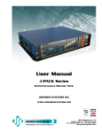
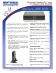
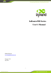
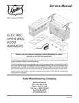
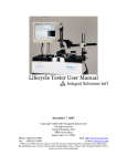
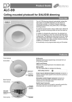
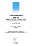
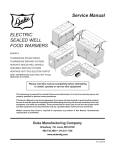
EXTC100
TEMPERATURE CONTROLLER WITH
GRAPHIC DISPLAY, + REMOTE
CONTROL
FEATURES
•
•
•
•
•
•
•
•
•
ATEX IECEx Hazardous area protected, safe in Zone 1 environment
Remote control
2, 3 or 4 wire PRT Thermometer probe input
Temperature range -200°C to +550°C (-328°F to +1022°F)
Operates with sensors from 100Ω to 1kΩ Platinum RTDs (PT100 to
PT1000)
Total accuracy ±0.5°C max
Simple 16 Amp relay output for heat control,
with open contacts or line voltage output.
Universal operating voltage: 85 – 265 Volts AC
85 – 370 Volts DC
Adjustable mounting bracket
APPLICATIONS
Trace heating control - Process control - Thermostat control – Heating control
Quintex GmbH – i_Park Tauberfranken 13 – 97922 Lauda-Königshofen – Germany
Tel: +49 9343 6130-0 – Fax: +49 9343 6130-105 – Mail: [email protected] – www.quintex.eu
Specification
Input:
Type:
Maximum range:
Standard RTDs:
Accuracy:
Display Resolution:
Output:
Type:
Rated Current:
Maximum breaking capacity:
Mechanical endurance:
Contact endurance
Supply:
No load input current:
No load input power:
Environment:
Storage temperature range:
Operating temperature range:
Hazardous area:
ATEX specification
…
IECEx specification
…
Physical:
Weight:
Size:
External connection ports:
Internal terminals:
Display:
Enclosure:
Mounting:
Optional bracket:
Remote control unit:
Intrinsically safe
Platinum Resistance thermometer
Typical temperature range -200°C to +550°C (PRT100)
RTD 0 to 10000Ω*
PT100, PT500*, PT1000*
*special order
EXTC100: +-0.5°C maximum + probe error
(see PRT selection)
1°C
RELAY 1, RELAY 3
SPST relay (FORM A) contacts.
Max 16A continuous, 230Vac
4000 VA
20 x 10 cycles
>3 x 10 cycles (250VAC@10A) resistive load
>1 x 10 cycles (250VAC@10A) inductive load
85 – 265 Volts AC
85 – 370 Volts DC
~6mA @ 236Vac
<1.5W
-65°C to +75°C
-40°C to +75°C
Zone 1 Ex d enclosure
2kG
150mm wide by 130 mm x 130 mm
3 x 20mm M20 threaded sockets*
*Must be fitted with ATEX/IECEX approved Ex d cable glands for use in
hazardous areas
10 Amp rated pluggable terminal block for line and Relay inputs / outputs
4 way + screen terminal block for RTD connection
128x64 Pixel White backlit graphic LCD
Glass fronted Ex d enclosure. Painted Aluminium body.
Stainless steel version is available on request.
2 x M6 Holes.
Stainless steel, two way adjustable bracket. Suitable for wall, ceiling or
unistrut type mounting.
ATEX EN 60079-0:2012
EN 60079-11:2012
Cert No: Baseefa 03ATEX0187
IECEx Cert No: IECEx BAS 12.0126
Size: 112mm x 62mm x 31mm
Battery: B135
Quintex GmbH – i_Park Tauberfranken 13 – 97922 Lauda-Königshofen – Germany
Tel: +49 9343 6130-0 – Fax: +49 9343 6130-105 – Mail: [email protected] – www.quintex.eu
Enclosure dimensions
Bracket dimensions
3mm stainless steel, EN316 material
2 way adjustable angle.
Quintex GmbH – i_Park Tauberfranken 13 – 97922 Lauda-Königshofen – Germany
Tel: +49 9343 6130-0 – Fax: +49 9343 6130-105 – Mail: [email protected] – www.quintex.eu
SETUP AND INSTALLATION
The cover is removed using 1.5mm hex key and hands unscrewing the lid.
The two foam packing pieces should be discarded. The top circuit board is removed by gently unclipping the
two prongs.
Note: The enclosure can be mounted either way up, and the top board can be rotated to ensure the
writing is the correct way up.
Removing the green terminal plug from the lower board facilitates easier wiring. Using long nose pliers is
recommended. The lower board can remain in place.
Power Connection diagram
Power connection and heat output relay.
The heat output is controlled by RL1. The line voltage can be provided via the RL1 terminal if the RL1-LINK
is fitted.
Warning: Mains voltages will be present on the heat output terminals if the link is fitted. Take precautions if
using the line voltage output and use double insulated wiring where required by local regulations and
legislation.
Connect supply to terminals 7 live, 8 Earth, 11 Neutral. 85-265VAC, 85 – 370 Volts DC.
Terminal 9 should already connect to the enclosure Earth screw in the base.
Quintex GmbH – i_Park Tauberfranken 13 – 97922 Lauda-Königshofen – Germany
Tel: +49 9343 6130-0 – Fax: +49 9343 6130-105 – Mail: [email protected] – www.quintex.eu
Remote controller
The IR900 is an Infra-red remote control, operating the temperature
controller through the front glass .
It has an intrinsically safe design with membrane keypad. ATEX and IECEx
approved.
One remote can operate all temperature controllers that are in range.
Password protection can be applied to individual temperature control units.
PRT CONNECTION
PRT Selection
The EXTC will measure 2,3 and 4 wire PRT thermometers. 4 wire are the best recommended, 3 wire less
accurate often used in industrial applications and 2 wire thermometers should be avoided.
The RTD calibration is performed in software within the EXTC100 and in accordance with IEC 60751 using
the Callendar Van Dusen equations. For accuracies refer to this standard, and the tolerances within the
CLASS A or CLASS B probes available. Also refered to as DIN standard probes also available in 1/3 or
th
1/10 DIN.
Tolerance chart for PRT thermometers
The total accuracy will be determined by the combination of the probe, plus the ADC measurement plus the
reference resistor (internal).
Quintex GmbH – i_Park Tauberfranken 13 – 97922 Lauda-Königshofen – Germany
Tel: +49 9343 6130-0 – Fax: +49 9343 6130-105 – Mail: [email protected] – www.quintex.eu
The EXTC will measure 2, 3 and 4 wire PRT thermometers. The standard range is for 100 Ohm PRT
(at 0.01°C)
To set the type of thermometer set the jumper links on the upper circuit board according to the following
table:
J1-4 jumper link table for PRT selection
JUMPER
4 wire*
3 wire
J1
X
J2
J3
X
J4
X
(X= fit link) *Factory default
Wiring positions:
2 wire
X
X
X
**
**Note 2: In addition to the jumpers, be sure to set the type of probe in the software menu screens.
Physical connector positions.
Numbered 1 to 5 left to right.
Note:
Terminal 5 can be used to connect a screen
from the cable, if E (PCB ring tab, shown) is
connected to Earth.
1 2 3 4 5
Quintex GmbH – i_Park Tauberfranken 13 – 97922 Lauda-Königshofen – Germany
Tel: +49 9343 6130-0 – Fax: +49 9343 6130-105 – Mail: [email protected] – www.quintex.eu
OPERATION
The EXTX100 has a 16A rated heat output relay. Set the “SETPOINT” temperature on the display, the
controller will measure the RTD / PRT and apply heat output if necessary.
Three LEDs on the controller indicate the status of the unit.
‘ACTIVE’ Red LED slow flashing indicates the unit is powered on and operating. Multiple flashes indicate the
remote control is being detected.
‘HEAT’ Green LED indicates that the measured temperature is lower than the setpoint and heating is on.
‘FAULT’ white LED flashed to draw attention that something is wrong. RL3 relay will now be open circuit.
Menus
All settings are retained in memory including when power is removed.
Use ‘*’ to exit the menu.
The menus with
∆
must be set on installation.
Normal operating screen.
Press any key to display the passcode entry screen
Top level menu, press 1,2 or 3 or *to exit
Quintex GmbH – i_Park Tauberfranken 13 – 97922 Lauda-Königshofen – Germany
Tel: +49 9343 6130-0 – Fax: +49 9343 6130-105 – Mail: [email protected] – www.quintex.eu
Set the desired set temperature.
Enter the number and use ‘#’ to input a negative number.
The number is not dependant on the units set and will remain
as that number even if the units are changed.
∆
HYSTERESIS
Enter hysteresis in degrees. Applies only to positive values
above the setpoint. Range 0-99.
Default: 0
Example: Set a Hysteresis of 1. Setpoint 25.
The heater will turn off as the temp changes from 26 to 27, and
will switch on as the temp drops from 25 to 24.
TOP LEVEL SETUP MENU
To Configure the unit for installation.
All these parameters need to be set upon installation.
Default values are as follows:
1. Output sense: 1
2. Temp fail mode: 2
3. Set Calibration: 0
4. Set Passcode: 1111
5. Set units: 1
6. 2,3 or 4 wire RTD: 2 (4 wire)
RL1 RELAY 1
Relay can be set to open to heat or close to heat.
RL1 can have line voltage output by linking ‘RL1-Link’
with a wire.
Default:1
∆
RL3 RELAY 3
Relay 3 can be set to open or close on a fault detected. RTD
probe failure or short etc.
Usual to have ‘fail open’, so a complete power down situation
can be detected remotely.
Default:2
Quintex GmbH – i_Park Tauberfranken 13 – 97922 Lauda-Königshofen – Germany
Tel: +49 9343 6130-0 – Fax: +49 9343 6130-105 – Mail: [email protected] – www.quintex.eu
OFFSET Calibration
This menu inputs an offset for the measured temperature. Use
with the correct sensor fitted and a reference probe and meter
or a fixed point calibration to compare readings.
Offset value only. The calibration curve is defined by IEC 60751
and a suitable Class A or Class B probe is necessary for high
accuracy. *
Default: 0
Replace the default passcode 111 1 with a different number.
Store a record in a safe place, the new number cannot be
retrieved.
Set the units to be displayed.
Press 1 for Celsius
2 for Fahrenheit
3 for Kelvin
Default: degrees C
Set the RTD type to match the hardware installed.
As well as setting the software here, the jumper links must be
adjusted on the upper circuit board, see chapter J1-4 “PRT
CONNECTION”
Default 2. (4-wire)
∆
FAULT FINDING
Problem:
Possible Causes
Fault light flashing:
1. The thermometer probe has a broken connection
‘TEMP PROBE FAILURE’
2. The thermometer probe has a shorted connection
3. The thermometer probe resistance has gone outside range (<10 Ω >390 Ω)
4. The 2,3-4 wire screen software selection is wrong for the type of probe
5. wiring fault
Red light not flashing:
No power to unit
Disconnected yellow interconnection lead in unit.
Green “HEAT” light on while RL1 off:
1. Screen setting. The green light shows when heating is applied. RL1 could be set
to open on heat. Set menu ‘SET OUTPUT RELAY’ if relay is incorrect.
Quintex GmbH – i_Park Tauberfranken 13 – 97922 Lauda-Königshofen – Germany
Tel: +49 9343 6130-0 – Fax: +49 9343 6130-105 – Mail: [email protected] – www.quintex.eu