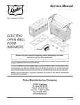
1
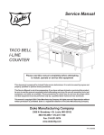
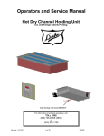
Service Manual
ELECTRIC
SEALED WELL
FOOD WARMERS
MODELS
THURMADUKE STEAM TABLES
THURMADUKE SERVING SYSTEMS
AEROHOT SEALED WELL MODELS
AEROSERV SERVING SYSTEMS
HERITAGE HOT FOOD ELECTRIC BUFFET
NEXT GENERATION ELECTRIC HOT FOOD
SERVING SYSTEMS
Please read this manual completely before attempting
to install, operate or service this equipment
This document is prepared for trained Duke service technicians. It is not to be used by anyone not
properly qualified to perform these procedures.
This Service Manual is not all encompassing. If you have not been trained on servicing this product,
be sure to read the manual completely before attempting servicing. Be sure all necessary tools, test
equipment, and skills are available. Those procedures for which you do not have the proper skills
and test equipment must be performed only by a qualified Duke trained service technician.
Written consent from Duke is required to reproduce any portion of this Manual. Unauthorized
reproduction is prohibited.
Duke Manufacturing Company
Broadway • St. Louis, MO 63102
800.735.3853 • 314.231.1130
www.dukemfg.com
P/N 219219B
Service Manual for Electric Sealed Well Food Warmers
IMPORTANT WARNING AND SAFETY INFORMATION
WARNING
READ THIS MANUAL THOROUGHLY BEFORE OPERATING, INSTALLING, OR
PERFORMING MAINTENANCE ON THE EQUIPMENT.
WARNING
FAILURE TO FOLLOW INSTRUCTIONS IN THIS MANUAL CAN CAUSE PROPERTY
DAMAGE, INJURY OR DEATH.
WARNING
DO NOT STORE OR USE GASOLINE OR OTHER FLAMMABLE VAPORS OR
LIQUIDS IN THE VICINITY OF THIS OR ANY OTHER APPLIANCE.
WARNING
DO NOT OPERATE THIS EQUIPMENT WITHOUT PROPERLY PLACING AND
SECURING ALL COVER AND ACCESS PANELS.
CAUTION
Observe the following:
•
Provide and maintain adequate minimum clearances from all walls and combustible materials.
•
Provide and maintain adequate clearance for air openings.
•
Keep the equipment area free and clear of combustible material.
•
Operate equipment only on the type of electricity indicated on the specification plate.
•
Retain this manual for future reference.
2
Service Manual for Electric Sealed Well Food Warmers
TABLE OF CONTENTS
SPECIFICATIONS............................................................................................................... 4
INSTALLATION................................................................................................................... 4
Location.......................................................................................................................... 4
Leveling........................................................................................................................... 4
Stabilizing........................................................................................................................ 4
Electrical Connection...................................................................................................... 4
PARTS REPLACEMENT..................................................................................................... 5
Infinite Switch Replacement............................................................................................ 5
Aerohot Sealed Well Models, AeroServ Serving System, Heritage Hot Food
Electric Buffet and Next Generation Electric Hot Food Serving System.................... 5
Aerohot ADI1SW through ADI5SW Models................................................................ 6
Electronic Thermostat Replacement............................................................................... 6
Aerohot ASI1SW through ASI5SW Models................................................................ 6
Thurmaduke Steam Tables and Thurmaduke Serving Systems................................ 7
Indicator Lamp Replacement.......................................................................................... 8
Power Toggle Switch Replacement – Thurmaduke Models............................................ 9
Element Replacement..................................................................................................... 9
Hi-Limit Thermostat Replacement................................................................................ 10
Carving Board Shelf Replacement.................................................................................11
Caster Replacement – Thurmaduke Serving System, AeroServ and
Heritage Models....................................................................................................... 12
Push Bar Replacement – Thurmaduke Serving System............................................... 12
Master Drain Valve Replacement................................................................................. 13
SERVICE INFORMATION................................................................................................. 15
Troubleshooting Procedure........................................................................................... 15
MAINTENANCE................................................................................................................ 16
Stainless Steel Care and Cleaning............................................................................... 16
Care and Cleaning – Painted and Powder Coated Units.............................................. 16
SCHEMATICS................................................................................................................... 17
3
Service Manual for Electric Sealed Well Food Warmers
SPECIFICATIONS
MODEL
DESCRIPTION
VOLTAGE
SIZE
E302SW – E305SW
Aerohot Sealed Well
115VAC, 208VAC & 236VAC
Variable 2 well to 5 well
ADI1ESW – ADI5ESW
Aerohot Drop-in Sealed Well
115VAC, 208VAC & 236VAC
Variable 1 well to 5 well
ASI1ESW – ASI5ESW
Aerohot Slide-in Sealed Well
115VAC, 208VAC & 236VAC
Variable 1 well to 5 well
E-2-CBSS – E-6-CBSS
Stainless Steel Thurmaduke
115VAC, 208VAC & 236VAC
Variable 2 well to 6 well
E-2-CBPG – E-6-CBPG
Painted Thurmaduke
115VAC, 208VAC & 236VAC
Variable 2 well to 6 well
E302-25 – E305-25
AeroServ Serving System
115VAC, 208VAC & 236VAC
Variable 2 well to 5 well
HB2HF – HB5HF
Heritage Buffet
115VAC, 208VAC & 236VAC
Variable 2 well to 5 well
TEHF-32 – TEHF88
Thurmaduke Serving System
115VAC, 208VAC & 236VAC
Variable 2 well to 6 well
NG32HF – NG74HF
Next Generation Hot Food
115VAC, 208VAC & 236VAC
Variable 2 well to 5 well
INSTALLATION
Location
The food warmers represented in this manual are
intended for indoor use only. Be sure the chosen
location has a floor strong enough to support
the total weight of the unit fully loaded with food
product. Reinforce the floor (stationary units) or
cabinet (drop-in or slide-in units) if necessary to
provide for maximum loading. Portable units (units
with optional casters) should be placed on a level
surface capable of supporting the unit’s fully loaded
weight. For the most efficient operation, be sure to
provide good air circulation inside and out.
Leveling
Be sure floor units are placed on a firm, flat surface/
floor. Check for cracks in flooring or tile and avoid
these areas if possible. If necessary place support
pads, properly rated for the weight of the unit, to
“bridge” uneven or cracked flooring. Level the unit
accordingly using the leg adjusters.
Make sure the top of the cabinet is level before
installing Aerohot drop-in or slide-in units. It may
be necessary to shim the unit or cabinet to make
it level.
Stabilizing
Use the leg adjustments to ensure that the unit
is solid to the floor surface at all contact points.
Ensure that the unit does not rock when pressure
is applied to the top corners. Units with casters
will require spacers to make them level on uneven
4
surfaces. The spacers should be placed under the
locking casters for maximum stability. Casters must
be locked when the unit is in service.
Electrical Connection
The Electric Sealed Well Food Warmers are
available as 115VAC, 208VAC, or 236VAC,
50/60 Hz. Portable units are available with a
properly rated and wired cord. Direct wiring of
units to the power supply must be performed by
a certified electrician and must comply with local
electrical codes for your municipality.
WARNING:
REFER TO THE AMPERAGE DATA
LIST IN THE SPECIFICATIONS OR
THE SERIAL TAG DATA AND YOUR
LOCAL CODE OR THE NATIONAL
ELECTRICAL CODE TO BE SURE UNIT
IS CONNECTED TO THE PROPER
POWER SOURCE. A PROTECTED
CIRCUIT OF THE CORRECT VOLTAGE
AND AMPERAGE MUST BE RUN FOR
CONNECTION OF THE SUPPLY CORD
OR PERMANENT CONNECTION TO THE
UNIT. THE POWER MUST BE TURNED
OFF AND DISCONNECTED WHENEVER
PERFORMING MAINTENANCE OR
REPAIR FUNCTIONS.
Service Manual for Electric Sealed Well Food Warmers
PARTS REPLACEMENT
WARNING
ALWAYS DISCONNECT THE UNIT
FROM ITS POWER SOURCE BEFORE
SERVICING.
INFINITE SWITCH REPLACEMENT
Aerohot Sealed Well Models, AeroServ
Serving System, Heritage Hot Food Electric
Buffet and Next Generation Electric Hot
Food Serving System
D1023
Figure 2. Removing bottom cover
2. Remove the screws that hold the bottom cover
in place (see Figure 2).
3. Slide the bottom cover toward the back of the
unit. Provide support for it to prevent damage
to the wiring harness.
Note: Tag the power cable wires and disconnect
them. Doing this allows for complete removal of
the bottom cover.
Infinite
Switch
Locking
Nut
D1022
Figure 1. Location of Infinite Switch
Infinite switches are located on the operator’s side
of the unit. Each switch is located directly below its
corresponding pan. Figure 1 depicts the location
of the switches on most sealed well units.
1. Disconnect unit from power source.
Knob
Guard
D1024
Figure 3. View of infinite switch wiring.
4. Tag and disconnect the infinite switch wiring.
An example of the infinite switch wiring is seen
in Figure 3.
5
Service Manual for Electric Sealed Well Food Warmers
5. Remove the knob.
6. Remove the two screws that secure the infinite
switch to the panel.
7. Remove the switch from the back of the
panel.
8. Install replacement infinite switch, mounting
screws and knob.
9. Reference the tags to reconnect the wires to
the infinite switch.
10. Reconnect the power wiring and reinstall the
bottom cover.
5. Tag and disconnect the infinite switch wiring.
Wiring is depicted in Figure 3.
6. Remove the knob.
7. Remove infinite switch mounting screws.
8. Remove the infinite switch from the remote
control panel.
9. Install replacement infinite switch, mounting
screws and knob.
10. Reference the tags to reconnect the wires to
the infinite switch.
11. Connect the unit to its power source.
11. Reinstall the back cover of the remote infinite
switch control.
Aerohot ADI1SW through ADI5SW Models
12. Reconnect the power wires and reinstall the
unit into the cabinet.
13. Connect the unit to its power source.
THERMOSTAT REPLACEMENT
Aerohot ASI1SW through ASI5SW Models
Remote Infinite Switch
D1025
Figure 4. Location of Infinite Switch –
Aerohot Drop-in (ADI) models
Infinite switches are located in a separate control
panel that is mounted to the front of the cabinet.
Figure 4 depicts an uninstalled ADI unit with the
remote infinite switch control panel.
1. Disconnect unit from power source.
2. Remove the screws that hold the unit and
its remote infinite switch controller in the
cabinet.
3. Pull the remote infinite switch controller out of
the cabinet for servicing.
4. Remove screws holding the back cover of the
remote infinite switch control panel in place.
6
Thermostats
D1026
Figure 5. Location of Thermostat – Aerohot
Slide-in (ASI) models
Thermostats are located in front on the control
panel below each pan. Figure 5 depicts the location
of the thermostat.
1. Disconnect the unit from its power source.
2. Slide the unit out of its cabinet.
3. Turn the unit upside down and remove the
screws that hold the bottom cover in place.
Service Manual for Electric Sealed Well Food Warmers
4. Slide the bottom cover toward the back of the
unit and lift it out as depicted in Figure 2.
Thurmaduke Steam Tables and Thurmaduke
Serving Systems
5. Tag and disconnect the thermostat wiring.
6. Remove the knob.
7. Remove the thermostat mounting screws.
8. Remove the thermostat and sensor probe.
9. Install the thermostat probe into the slide-in
tube in the pan.
Note: Do not kink the thermostat probe when
reinstalling it.
10. Install the new thermostat, mounting screws
and knob.
11. Reference the tags to reconnect the wiring to
the thermostat.
12. Install the bottom cover.
13. Slide the unit back into its cabinet.
14. Connect the unit to its power source.
D1027
Figure 6. Location of Thermostat –
Thurmaduke models
Thermostats are located on the operator’s side
of the Thurmaduke models as depicted in Figure
6. Each thermostat is mounted directly below the
sealed pan it controls.
1. Disconnect unit from power source.
2. Remove the screws that hold the bottom cover
(see Figure 2) in place.
3. Slide the bottom cover toward the back of the
unit. Provide support for it to prevent damage
to the wiring harness.
Note: Tag the power cable wires and disconnect
them. Doing this allows for complete removal of
the bottom cover.
4. Tag and disconnect the thermostat wiring.
5. Remove the knob guard. The knob guard is
held on by two locking nuts on the inside of
the front panel.
6. Remove the knob.
7. Remove the screws securing the thermostat
to the panel.
7
Service Manual for Electric Sealed Well Food Warmers
8. Remove the thermostat from the back of the
panel.
9. Install replacement thermostat, mounting
screws, knob and knob guard.
White wires to
Indicator Lamp
Indicator
Lamp
10. Reference the tags to reconnect the wires to
the thermostat.
11. Reconnect the power wires and reinstall the
bottom cover.
12. Connect the unit to its power source.
INDICATOR LAMP REPLACEMENT
D1029
All Models Except ADI / Areohot Models
Figure 8. Inside of panel showing location
of pan indicator lamp
Indicator Lamp
4. Pan Indicator Lamps – Disconnect the indicator
lamp wiring from the infinite switch or electronic
thermostat as depicted in Figure 8.
Power Indicator Lamp (Thurmaduke models
only) – Disconnect the indicator lamp wires
from the back of the power toggle switch.
D1028
Figure 7. Location of Pan Indicator Lamp
The pan indicator lamp is located on the control
panel above the infinite switch or electronic
thermostat on all electric units as depicted in Figure
7. The lamp is lit when the pan is in operation.
Thurmaduke models are equipped with a poweron indicator lamp located next to the power toggle
switch on the operator’s right side.
1. Disconnect unit from power source.
Note: Slide-in and drop-in units must be removed
from their cabinets.
2. Remove the screws that hold the bottom cover
in place.
3. Slide the bottom cover toward the back of the
unit and lift it out as depicted in Figure 2.
8
5. Remove the indicator lamp assembly. The
lamp is held in place by crimp springs.
6. Replace the indicator lamp assembly.
7. Replace the lamp with a new one.
Note: If the lamp assembly is held on by a nut,
the nut must be screwed on prior to reattaching
the lens.
8. Reconnect the indicator lamp wiring.
9. Reconnect the power wires and install the
bottom cover.
10. Connect the unit to its power source.
Service Manual for Electric Sealed Well Food Warmers
POWER TOGGLE SWITCH REPLACEMENT
6. Install replacement toggle switch.
Thurmaduke Models
7. Reference the tags to reconnect the wires to
the toggle switch.
8. Reconnect the power wires and reinstall the
bottom cover.
9. Connect the unit to its power source.
ELEMENT REPLACEMENT
All Models
D1030
Figure 9. Location of power toggle switch
on all Thurmaduke models
All Thurmaduke models are equipped with a
power toggle switch. The switch is located on the
operator’s control panel to the right of the power
indicator lamp as depicted in Figure 9.
1. Disconnect unit from power source.
2. Remove the screws that hold the bottom cover
in place (see Figure 2).
3. Slide the bottom cover toward the back of the
unit. Provide support for it to prevent damage
to the wiring harness.
Note: For easier access, tag power cable wires
then disconnect and remove the bottom cover.
4. Tag and disconnect the power toggle wiring.
5. Remove the toggle switch. It may be held in
place by crimp springs, screws or a spin nut
on the toggle shaft. Toggles that are held in
by screws or a spin nut will be removed from
the rear of the panel. Toggles held in place by
crimp springs will be removed by squeezing
the crimp springs and pushing the toggle out
through the front of the panel.
Element
Pan
Heat
Element
D1031
Figure 10. Location of heat elements
The heat element is located under each pan and
is housed in an element pan for protection as
depicted in Figure 10. Use replacement elements
that are rated for the model being serviced.
1. Disconnect unit from power source.
Note: Drop-in and slide-in units must be removed
from their cabinets.
2. Remove the screws that hold the bottom cover
in place.
3. Slide the bottom cover toward the back of the
unit and lift it out as depicted in Figure 2. In
order to protect the wiring, either the bottom
cover must be supported to prevent damage
or the wiring must be tagged and disconnected
with the cover set aside for reassembly.
4. Tag and disconnect the element wiring.
9
Service Manual for Electric Sealed Well Food Warmers
12. Replace the lock nuts to secure the element
pan in place under the sealed pan.
13. Reference the tags to connect element
wiring.
14. Reconnect the power wires and install the
bottom cover.
15. Connect the unit to its power source.
Element
Pan
Lock
Nuts
D1032
Figure 11. Location of element pan lock
nuts, two each side
HI-LIMIT THERMOSTAT REPLACEMENT
All Models
5. Remove the lock nuts that hold the element
pan to the bottom of the sealed pan as depicted
in Figure 11.
6. Slide the element pan away from the drain
support and out of the unit.
7. Remove the element support clips on the end
of the pan.
8. Remove the element from the center support
bracket and lift it out of the element pan.
Element
Element
Support
High-limit
Thermostat
Lock
Nut
D1034
Figure 13. Location of the Hi-Limit
Thermostat
The hi-limit thermostatic switch is located on
the bottom of each pan next to the element wire
connections. It is connected directly to the sealed
pan as depicted in Figure 13.
D1033
1. Disconnect unit from power source.
Figure 12. Element replacement
2. Remove the bottom cover as depicted in
Figure 2.
9. Replace the element. Gently flex element to fit
it securely under the center support bracket.
Note: Tag and disconnect the power wires, set
the bottom cover aside for reassembly.
Caution:
3. Tag the wires to the hi-limit thermostatic switch
and disconnect them.
Use care when handling the new
element. Elements can break
very easily.
10.Replace the element support clips that support
the element loops on the edge of the pan.
4. Remove the lock nut that holds the hilimit thermostat in place and lift the hi-limit
thermostatic switch off of its mounting stud.
11. Place the element pan over the studs on the
sealed pan.
5. Place the new hi-limit thermostatic switch onto
the mounting stud.
10
Service Manual for Electric Sealed Well Food Warmers
6. Replace the lock nut.
Caution:
Do not overtighten the lock nut.
Overtightening will damage the
hi-limit thermostat.
7. Reference the tags to reconnect the hi-limit
thermostatic switch wiring.
8. Reconnect the power wires and install the
bottom cover.
9. Connect the unit to its power source.
D1036
CARVING BOARD SHELF REPLACEMENT
All Models
Figure 15. Carving board mounting stud
1. Lift the carving board off its mounting studs
as depicted in Figure 15.
Carving
Board
D1037
Figure 16. Carving board shelf
mounting brackets
Carving Board Shelf
D1035
Figure 14. Location of Carving Board Shelf
The carving board and carving board shelf are
located on the server’s side of the unit as depicted
in Figure 14. If needed, the carving board is
replaceable as a separate unit. Aerohot Drop-in
and Slide-in units are not available with carving
boards.
2. Loosen the top screw in the slotted hole at the
top of the bracket on both sides of the unit as
depicted in Figure 16.
3. Remove the rest of the screws that hold the
shelf on the unit.
4. Lift the shelf up and away from the unit.
5. Replace the shelf with the new one.
6. Reinstall the screws.
7. Tighten the screws in the slotted holes.
8. Insert the new carving board onto the mounting
studs on the shelf.
11
Service Manual for Electric Sealed Well Food Warmers
CASTER REPLACEMENT
Thurmaduke Serving System, AeroServ and
Heritage Models
Figure 18. Location of mounting holes
on caster flange
5. Slide the old caster off of the leg channel.
6. Line up the holes in the caster flange with the
mounting holes in the leg channel.
7. Slide the new caster into position.
Always replace locking casters with locking
casters.
8. Reattach and tighten the mounting screws.
9. Remove the unit from the supports.
10. Reconnect the unit to its power source.
PUSH BAR REPLACEMENT
D1038
Figure 17. Units with casters
Thurmaduke, AeroServ and Heritage models are
supplied with NSF listed 5" black swivel casters.
Each unit is supplied with a pair of locking
casters.
Thurmaduke, AeroServ and Heritage
Serving Systems
Push
Bar
1. Disconnect the unit from its power source.
2. Make sure pans have been completely
emptied.
3. Raise and support the side of the unit that
requires a new caster.
4. Remove the four screws that hold the caster
to the channel at the bottom of the unit.
D1040
Figure 19. Push bar on Thurmaduke Serving
Systems
Push bars are mounted on the side of the serving
system that has the locking casters. Generally, this
is the operator’s right side. Push bars are optional
with the Thurmaduke, Heritage and AeroServ
Serving Systems.
1. Remove the unit from its power source.
Mounting
screws
12
D1039
2. Remove the bottom cover as depicted in
Figure 2.
Service Manual for Electric Sealed Well Food Warmers
Retaining
Nuts
Retaining
Screws
MASTER DRAIN VALVE REPLACEMENT
All Models
OFF
LO
H
I
2
6
3
4
5
OFF
LO
H
I
2
6
3
4
5
OFF
LO
H
I
2
6
3
4
5
OFF
LO
H
I
2
6
3
4
5
D1041
D1042
Figure 20. View of Push Bar
retaining nuts/screws.
3. Remove the retaining nuts and washers from
the push bar studs.
4. Gently pull the push bar free of the unit.
Caution:
Be very careful when removing
the push bar from painted
models to prevent scratching or
peeling of paint.
Figure 21. Location of Master Drain Valve
All sealed well units are provided with a drain
system. The drain system may be provided in
copper or PVC depending on the model. The
master drain valve is located below the drain
manifold as depicted in Figure 21.
1. Disconnect the unit from its power source.
2. Make sure pans are drained.
5. Insert new push bar into handle holes in the
unit.
OF
F
LO
H
I
2
6
5
F
4
OF
LO
H
I
2
6
3
4
5
7. Reattach any wires that were disconnected
when the bottom cover was removed.
3
6. Reattach washers and nuts.
8. Reinstall the bottom cover.
9. Connect the unit to its power source.
Hold fitting steady
with a properly
sized wrench.
D1043
Figure 22. Master Valve and Valve Fitting
3. Remove the old valve.
13
Service Manual for Electric Sealed Well Food Warmers
Caution:
The valve may be very tight. It is
important to hold the pipe fitting
(see Figure 22) with a wrench of
the proper size connected to the
coupler to prevent damage to the
plumbing. Copper is a very soft
material and will bend. PVC is
brittle and breaks very easily.
4. Apply pipe sealer (“pipe dope”) to the threads
of the new valve.
5. Screw the new valve onto the pipe fitting on
the manifold. Make sure it is tight but do not
overtighten it.
6. Test the valve for leaks. Tighten as
necessary.
7. Reconnect the unit to its power source.
14
Service Manual for Electric Sealed Well Food Warmers
SERVICE INFORMATION
TROUBLESHOOTING PROCEDURE
SYMPTOM
Element does not heat
Unit not level (wobbles)
Master valve leaks
Wells will not drain
CAUSE
Unit not plugged in
No power to unit
Defective thermostat or infinite switch
Open hi-limit thermostat
Open element
Legs not adjusted properly (floor models)
Cabinet not level (drop-in or slide-in units)
Compression fitting not tight enough
Valve mechanism worn
Master valve closed
Master valve clogged Valve handle moves but does not open valve
REMEDY
Plug unit in
Check circuit breakers or fuses
Replace with proper part rated for the model
Replace hi-limit thermostat
Test for continuity and replace if necessary
Using the leg adjusters, adjust the legs until level
Shim cabinet until level
Tighten the compression fitting
Replace master valve
Open valve
Remove, clean and replace valve
Replace valve with new one
15
Service Manual for Electric Sealed Well Food Warmers
MAINTENANCE
STAINLESS STEEL CARE AND CLEANING
Stainless steel contains 70-80% iron. Iron will rust.
It also contains 12-30% chromium. Chromium
forms an invisible, passive film over the steel
surface and acts as a shield against corrosion. As
long as the protective film remains intact, the metal
will not corrode. However, if the film is broken or
contaminated, outside elements can begin to break
down the steel and form rust or discoloration. To
prevent rust and discoloration on stainless steel,
several important steps need to be taken.
CAUTION: Never use steel wool pads, wire
brushes or scrapers.
CAUTION: Never use an acid-based
cleanser! Be sure to clean
all food products from any
stainless surface. Many food
products contain acid, which can
deteriorate the finish. Common
foods include tomatoes, peppers
and other vegetables.
CARE AND CLEANING: PAINTED OR
POWDER COATED UNITS
Use non-alkaline-based or non-chloride cleaning
solutions. Anything containing chloride will damage
the protective film on stainless steel. Chlorides
are found in household and industrial cleaners
and also in hard water and salts. If a chloride or
alkaline cleaner has been used, rinse repeatedly
and dry thoroughly.
Paint and Powder Coat are applied finishes. They
are applied to a paint-ready steel surface. Like
stainless steel, units with these coatings should be
cleaned with mild soap and a soft cloth. Stubborn
stains can be removed with a plastic scrubbing
pad. Never use abrasive materials to clean painted
or powder coated surfaces. After cleaning with
mild soap and a soft cloth, painted and powder
coated surfaces must be rinsed with warm water
and a soft cloth to remove soap residue. Always
wipe painted or powder coated surfaces dry with
a soft dry cloth after they are cleaned.
Always use only soft cloths or plastic scouring pads.
For routine cleaning, use warm soapy water. For
stubborn stains, use a non-abrasive cleanser. For
heavy grease, use a degreaser. For best results,
rub with the grain of the steel.
WARNING:
Avoid cleaning solutions that
contain alkaline or chloride.
Pitting and cracking are early signs of stainless
steel breakdown. Special stainless steel cleaners
can restore and preserve the protective film. If
signs of breakdown appear, thoroughly clean
and dry all surfaces. Begin regular application of
a high quality stainless steel cleaner according to
the manufacturer’s instructions. Again, always rub
with the grain of the steel for best results.
16
THE POWER MUST BE TURNED OFF
AND DISCONNECTED AT ALL TIMES
DURING MAINTENANCE OR REPAIR
FUNCTIONS.
Service Manual for Electric Sealed Well Food Warmers
SCHEMATICS
L1
L2
G
P
H
1
L1
L2
H2
P
L1
H
1
L2
H2
Single Phase 120VAC to 240VAC with Infinite Switch
L1
L2
G
Single Phase 120VAC to 240VAC with Thermostatic Control
L1
L2
L3
G
P
H
1
L1
L2
H2
P
H
1
L1
L2
H2
P
H
1
L1
L2
H2
Three Phase 120VAC to 240VAC with Infinite Switch.
L1
L2
L3
G
Three Phase 120VAC to 240VAC with Thermostatic Control
Figure 23. Schematics of Sealed Well Units with Electronic Thermostats or Infinite Switches
17
Service Manual for Electric Sealed Well Food Warmers
NOTES:
18
Service Manual for Electric Sealed Well Food Warmers
19
Service Manual for Electric Sealed Well Food Warmers
Duke Manufacturing Company
Broadway • St. Louis, MO 63102
800.735.3853 • 314.231.1130
www.dukemfg.com
20
P/N 219219B