1
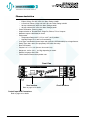
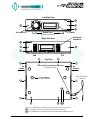
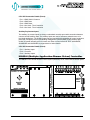
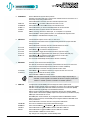
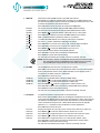
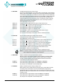
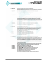
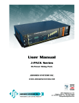
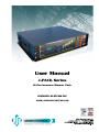
User Manual
J-PACK Series
Hi-Performance Dimmer Pack
JOHNSON SYSTEMS INC.
WWW.JOHNSONSYSTEMS.COM
Contents
Warranty...........................................................................................................2
Introduction.......................................................................................................3
Characteristics..................................................................................................4
Installation........................................................................................................6
Mounting Options.............................................................................................6
AC Power Supply Input Options.......................................................................8
Output Connector/Receptacle Options...........................................................10
Output Connector/Receptacle Diagrams........................................................12
Control Input...................................................................................................12
MADD-6 (Multiple Application Dimmer Driver) Controller...............................13
User Interface.................................................................................................14
System Status • LED Indicators ....................................................................15
System Status • LCD Display.........................................................................15
Quick Programming Reference to System Configuration Menu Items...........17
Detailed Programming of System Configuration Menu Items........................18
Important Hard-key Information......................................................................28
J-PACK Dimmer Pack (DP) Ordering Information..........................................29
Troubleshooting Reference............................................................................30
Warranty
J-PACK Series dimmer packs come with a standard one (1) year
limited warranty. Extended warranties of up to ten (10) years are
available at the time of purchase.
For details visit: www.johnsonsystems.com/warranties.htm
For Technical Assistance
1. Refer to your product user manual. The most current revision is
available online: www.johnsonsystems.com/literature.htm
2. Contact the “point-of-sale” dealer or distributor from which this product
was originally purchased, and ask for technical assistance.
3. If neither of the above can provide you with the necessary information,
please contact our factory via email ([email protected])
or phone (403-287-8003) during business hours (Monday to Friday,
8:00AM to 5:00PM MST).
2
WWW.JOHNSONSYSTEMS.COM
Introduction
J-PACK Series
Hi-Power Dimmer Pack
J-PACK dimmers are a truly universal hi-performance series of 6 channel
dimmer packs. Designed for versatility in virtually any environment, these unique
and compact dimmer packs can be wall-mounted for permanent installations,
19” rack mounted, pipe mounted or used as portable units. Multiple units can be
easily “ganged” together for fast system expansion.
Next generation “system-on-a-chip” technology provides unsurpassed value
in SCR dimming. Stand-by power consumption of less than 1 Watt, allow
for compliance with the International Energy Agency’s “One Watt Initiative”
for standby power consumption. This makes J-PACK’s truly “green” with the
minimal possible impact on the environment!
Available in various sizes and configurations, J-PACK’s offer unique flexibility
in professional grade dimming. Designed for modern lower wattage compact
filament dimming loads these dimmers are full rated at 1,560 Watts for constant
prolonged operation. Premium hydraulic magnetic circuit breakers offer safety
and eliminate the false tripping concern of competitive dimmers. Intuitive LCD
user interface combined analog inputs and contact closure inputs allow for
industry wide application.
On demand “MagLev®” thermal management technology produces superior
cooling that is virtually silent making J-PACK’s the natural choice for “quiet
space” dimming installations. Exclusive “lamp warming” techniques extends
lamp life considerably while maintaining industry leading performance!
Features
• Available in a range of voltage and output configurations.
• Unique power saving stand-by mode reduces power consumption to less
than 1 Watt, a “green” dimmer pack.
• Dim standard or low-voltage incandescent quartz lamps. Compatible with
SCR dimmable LED lamps and fixtures.
• Individual dimmer profile selection permits safe and silent control of nondim lighting loads.
• DMX512 start addressable in single channel (offset) or individually (patch).
• DMX “snapshots” with scene playback.
• Unique “lamp warming” feature extends lamp life significantly.
• Analog and dedicated dry contact BMS inputs for interface with HVAC,
security and audio.
• “Load Shed” inputs for power management and photocell interface.
• LCD user interface for easy setup and monitoring.
• Over-heat and over-current protected.
• Non-proprietary dimmer SCR’s are 300% rated.
• On-demand ‘MagLev®’ thermal management technology produces superior
cooling that is virtually silent.
• Up to 10 year product warranty available!
WWW.JOHNSONSYSTEMS.COM
3
Characteristics
• Maximum Feeder Capacity:
• Edison 15 Amp 120 VAC 1Ø 3 wire. Max. Rating 1,800W.
• 2 Circuits of Edison 15 Amp 120 VAC 1Ø 3 wire. Max. Rating 3,600W.
• 30 Amp 120/208 VAC 3Ø 5 wire. Max. Rating 9,000W.
• 40 Amp 120/240 VAC 1Ø 4 wire. Max. Rating 9,000W.
• Power Termination: Power lug input.
• Output selection of Terminal Block, Stage Pin, Edison, TLG or Socapex.
• Maximum output 1,560 Watts per circuit.
•Environment
• Temperature Range: 23°F (-5°C) to 104°F (40°C) ambient.
• Humidity Range: 0% to 90% non-condensing.
• Load Type: Incandescent quartz lamps and electronic (SCR dimmable) low voltage fixtures.
• Switch Type: 300% rated, non-proprietary SCR solid state relay.
• Rise Time: 300uS.
• Physical: 13" x 17" x 3.4" (33 cm x 43 cm x 8.5 cm).
• Weight: 22 - 23 lbs. (10.0 - 10.5 Kg) depending on model.
• Material: 18-gauge steel CRS.
• Finish: Hammer texture black powder coat.
Front View
User Interface
Refer to page 14 for details
Control Input XLR Connectors
Refer to page 13 for details
4
WWW.JOHNSONSYSTEMS.COM
Circuit Breakers
Left Side View
Air Intake Fan
Rubber Feet
(For RF model only)
Handle
Right Side View
Air Exhaust
Ventilation
Top View
Air
Intake
Four (4) Safety Cable Mounting Holes
(For PM model only)
Six (6) Indents
(For vertical stacking)
Air
Exhaust
Safety Cable supplied
on PM model
Ten (10) SEMS #6-32 x 3/8" Philips Pan Head, Top Panel (Lid) Mounting Screws
Six (6) #6-32 x 3/8" Philips Flat Head, Top Panel (Lid) Mounting Screws
Four (4) SEMS #6-32 x 3/8" Philips Pan Head, Rack Mount Bracket Mounting Screws
WWW.JOHNSONSYSTEMS.COM
5
Installation
J-Pack Series dimmer packs are intended for indoor use only, in a controlled environment at a room
temperature.
•
•
•
•
•
Mount in a suitable location.
Refer to the Mounting Options section on page 6 for applicable details.
Connect the applicable AC power supply input.
Refer to the AC Power Supply Input Options section on page 8 for applicable details.
Connect the relay output receptacles/terminals.
Refer to the Relay Output Connection Options section on page 10 for applicable details.
Connect DMX and/or dry contact control input(s).
Refer to the Control Input section on page 12 for details.
Program, setup, test and verify functionality.
Refer to the Detailed Programming of System Configuration Menu Items section
on page 18 for details.
WARNING: For indoor use only!
Mounting Options
J-PACK Series dimmer packs are capable of various mounting options to suit the application required.
A cooling fan mounted inside the dimmer pack is used to move air through the chassis and cool
the heat sink and chokes. The fan is temperature controlled via a temperature sensor mounted on
the heat sink. If the heat sink temperature is >=55ºC the fan is turned on to half speed. If the heat
sink temperature is >=70ºC the fan is turned full on. It is important to mount the dimmer pack in the
orientation intended with unobstructed ventilation to ensure adequate cooling.
RF = Rubber Feet
For portable applications, the dimmer pack
can be set on any flat surface. Rubber feet are
mounted on the bottom of the dimmer pack,
with indents on the top cover panel to facilitate
vertical stacking of up to 6 units high.
WARNING: Never place the dimmer packs
side by side (horizontally) without
a minimum of 12" of clearance
between them. Always leave a
minimum of 6" of clearance from
the dimmer packs air intake and
exhaust. Failure to comply may
cause thermal overheating.
6
WWW.JOHNSONSYSTEMS.COM
PM = Pipe Mount
For pipe mounting, a bracket, C-clamp and safety cable are
provided and must be used to secure the dimmer pack to
standard pipe sizes from 1" to 2" (1.25" to 2.375" outside
diameter).
WARNING: Ensure the pipe is secure and rated adequately
for local rigging codes.
Ensure the safety cable is fastened correctly to
secure the dimmer pack.
WM = Wall Mount
For permanent applications, the dimmer pack can be mounted
to any wall surface capable of supporting its weight. Using the
four (4) mounting holes provided, 1/4" (6mm) screws or bolts
are required to fasten and secure the rack safely to the wall.
WARNING: Never mount the dimmer packs side by
side (vertically) without a minimum of 12"
of clearance between them. Always leave a
minimum of 6" of clearance from the dimmer
packs air intake and exhaust. Failure to comply
may cause thermal overheating.
RM = Rack Mount
For rack mounting, brackets are provided and used to secure
the dimmer pack in a standard 19" rack.
WARNING: Ensure there is sufficient ventilation provided
when mounting multiple dimmer packs within a
19" rack. The internal ambient temperature of
the rack must not exceed 104°F (40°C). Failure
to comply may cause thermal overheating.
Ensure there is adequate rear support provided
to maintain the dimmer pack position inside the
19" rack.
WWW.JOHNSONSYSTEMS.COM
7
AC Power Supply Input Options
J-PACK Series dimmer packs are capable of various 120VAC power supply input
configurations.
AC Power Supply
Input Terminals
Remove the top panel (lid) of the dimmer pack chassis to access the contractor
termination area, where the required AC power supply input terminals are
located. To remove the top panel (lid), remove the ten (10) SEMS #6-32 x 3/8"
Philips pan head mountings screws located on the sides and the six (6) #632 x 3/8" Philips flat head mounting screws located on the top, using a Philips
#2 screwdriver, and carefully lift the lid up. The cooling fan is mounted on the
lid, so be careful not to strain the fan wiring cable. If the fan cable needs to
be disconnected, carefully cut off the strain relief wire tie and unplug the fan
connector from the J10 PCB connector. Be sure to save the mounting screws to
secure the top panel (lid) once the AC power supply input wiring termination is
complete.
A 1.109" knockout (suitable for 0.75" conduit) located on the rear panel of the
relay pack chassis is provided for wire/conduit entry to the AC power supply
input terminals. Ensure an adequate fitting is used to secure the conduit to the
rear panel. Only use wire rated for the specifications provided. Route the wire
directly from the conduit entry into the power terminals. Use a 3/16" flathead
screwdriver to torque the power terminals to the specifications provided.
Once the AC power supply input wiring termination is complete, carefully
reinstall the top panel (lid). If the cooling fan cable was disconnected, be sure
to reconnect it to the J10 PCB connector, and install a wire tie for strain relief.
Carefully slide the lid down into place, making sure the fan cable does not get
pinched in the metalwork. Secure the lid using the mounting screws previously
removed. To ensure ground continuity between all chassis panels, be sure to use
the SEMS mounting screws with integral star washers on the sides.
WARNING: All wiring must comply with local electrical codes and be
completed by qualified personnel only!
WARNING: For connection use copper wire only, rated for 167ºF (75ºC)
minimum!
WARNING: All AC power supply input options require an external disconnect!
WARNING: Ensure the AC power supply external disconnect is turned off and
locked out while wiring terminations are completed!
WARNING: For permanent installations, the external disconnect must be
located adjacent to the equipment.
AVERTISSMENT: Pour les installations permanentes, le débrancher externe
doit être trouvé adjacent à l'équipement.
8
WWW.JOHNSONSYSTEMS.COM
120 = 120VAC 1Ø 3-Wire via a Single 5' Edison Power Cord
Includes a single factory installed 5' (1.5m) Edison power cord. Connect the
cables to a standard Edison (NEMA 5-15) receptacle, protected with a circuit
breaker rated at a maximum of 15 Amps.
• Up to 15 Amps – maximum 1,800W total.
• Internal electrical wiring termination is not required.
• Available only with Duplex Edison output connectors/receptacles.
120 = 120VAC 1Ø 3-Wire via Dual 5' Edison Power Cord
Includes two (2) factory installed 5' (1.5m) Edison power cords. Connect the
cables to standard Edison (NEMA 5-15) receptacles, each protected with a
circuit breaker rated at a maximum of 15 Amps.
•
•
•
•
•
2 circuits of up to 15 Amps – maximum 3,600W total.
Internal electrical wiring termination is not required.
Dimmers 1, 3 and 5 are powered from a single power cord.
Dimmers 2, 4 and 6 are powered from a single power cord.
Available only with Duplex Edison (NEMA 5-15) output connectors/
receptacles.
120/240 = 120/240VAC 1Ø 4-Wire Terminal Block
• Up to 40 Amps per phase – maximum 9,000W total.
• Use wire size #12 to #4 AWG copper wire only, rated for 167°F (75°C)
minimum.
• Strip insulation length to 0.44" (11mm).
• Torque power terminals (A, B, N, ) to 10.5 IN-LBS (1.2 NM).
• Dimmers 1, 3 and 5 are powered from Phase A.
• Dimmers 2, 4 and 6 are powered from Phase B.
120/208 = 120/208VAC 3Ø 5-Wire Terminal Block
• Up to 30 Amps per phase – maximum 9,000W total.
• Use wire size #12 to #4 AWG copper wire only, rated for 167°F (75°C)
minimum.
• Strip insulation length to 0.44" (11mm).
• Torque power terminals (A, B, C, N, ) to 10.5 IN-LBS (1.2 NM).
• Dimmers 1 and 4 are powered from Phase A.
• Dimmers 2 and 5 are powered from Phase B.
• Dimmers 3 and 6 are powered from Phase C.
WARNING: Ensure all AC power supply connections are tightened to the
torque specification provided, before turning on the AC power
supply!
Ensure all chassis panels are secure before turning on the AC
power supply!
WWW.JOHNSONSYSTEMS.COM
9
Output Connector/Receptacle Options
J-PACK Series dimmer packs are designed for high performance dimming of standard
incandescent, quartz, and dimmable (SCR/Leading-Edge) electronic low-voltage fixtures. The
dimmer outputs may be configured for non-dimmed applications when switched (relay controlled)
load outputs are required. Six (6) 1,560 Watt dimmer output circuits are fully protected by
premium 13 Amp hydraulic magnetic circuit breakers. Each of the dimmer outputs are connected
via various optional output connectors/receptacles.
120VAC Operation with Factory Installed Single or Dual Edison Power Cord
Capable of dimming six (6) 1,560 Watt dimmer output circuits, fully protected by premium 13 Amp
hydraulic magnetic circuit breakers. Powered with single or dual 120VAC 1Ø 3-Wire, each hot leg
is dimmed independently through six (6) Solid State Relays (SSR). J-PACK Series dimmer packs
supplied with a factory installed single (1) Edison power cord are capable of dimming a total of
1,800 Watts shared between the six (6) Duplex Edison output connectors. J-PACK Series dimmer
packs supplied with factory installed dual (2) Edison power cords are capable of dimming a total
of 3,600 Watts shared between the six (6) Duplex Edison output receptacles.
120VAC Output Receptacle with Factory Installed Single or Dual Edison Power Cord
• ED = 15A Duplex Edison (NEMA 5-15)
120VAC Operation
Capable of dimming six (6) 1,560 Watt dimmer output circuits, fully protected by premium 13 Amp
hydraulic magnetic circuit breakers. Powered with 120/240VAC 1Ø 4-Wire or 120/208VAC 3Ø
5-Wire, each hot leg is dimmed independently through six (6) Solid State Relays (SSR). Capable
of dimming a total of 9,000 Watts shared between the six (6) output connectors/receptacles.
120VAC Output Connector/Receptacle Options
•
•
•
•
SP = 20A Stage Pin (Bates)
TL = 20A Twist Lock Ground (TLG) (NEMA L5-20R)
SO = 19-Pin Socapex
TB = Terminal Block
19-Pin Socapex Connection Details (Pinout)
Pin 1 = Circuit 1 Hot
Pin 2 = Circuit 1 Neutral
Pin 3 = Circuit 2 Hot
Pin 4 = Circuit 2 Neutral
Pin 5 = Circuit 3 Hot
Pin 6 = Circuit 3 Neutral
Pin 7 = Circuit 4 Hot
Pin 8 = Circuit 4 Neutral
Pin 9 = Circuit 5 Hot
Pin 10 = Circuit 5 Neutral
10
Pin 11 = Circuit 6 Hot
Pin 12 = Circuit 6 Neutral
Pin 13 = Circuit 1 Ground
Pin 14 = Circuit 2 Ground
Pin 15 = Circuit 3 Ground
Pin 16 = Circuit 4 Ground
Pin 17 = Circuit 5 Ground
Pin 18 = Circuit 6 Ground
Pin 19 = Not Used
WWW.JOHNSONSYSTEMS.COM
Terminal Block Connection Details
NOTE: This option is intended for permanent installation
application only.
Remove the top panel (lid) of the dimmer pack chassis to access
the contractor termination area, where the required dimmer output
(load) terminals are located. To remove the top panel (lid), remove
the ten (10) SEMS #8-32 x 3/8" Philips pan head mountings
screws located on the sides and the six (6) #8-32 x 3/8" Philips
flat head mounting screws located on the top, using a Philips #2
screwdriver, and carefully lift the lid up. The cooling fan is mounted
on the lid, so be careful not to strain the fan wiring cable. If the fan
cable needs to be disconnected, carefully cut off the strain relief
wire tie and unplug the fan connector from the J10 PCB connector.
Be sure to save the mounting screws to secure the top panel (lid)
once the dimmer output (load) wiring terminations are complete.
Load (Hot)
Terminals
Neutral
Terminals
Ground
Terminals
In suitable locations on the rear panel of the relay pack chassis,
knockout suitable hole sizes for wire/conduit entry to the output
(load) terminals. Ensure an adequate fitting is used to secure the
conduit to the rear panel. Only use wire rated for the specifications
provided below. Route the wire directly from the conduit entry into
the output (load) terminals. Use a 3/16" flathead screwdriver to
torque the power terminals to the specifications provided below.
Each dimmer output (load) circuit (120VAC 1Ø 3-Wire) requires
three (3) conductors; one (1) for hot, one (1) for neutral and one
(1) for ground. There are six (6) hot terminals, six (6) neutral
terminals and six (6) ground terminals, one for each dimmer
output connection.
Once the dimmer output (load) wiring terminations are complete,
carefully reinstall the top panel (lid). If the cooling fan cable was
disconnected, be sure to reconnect it to the J10 PCB connector,
and install a wire tie for strain relief. Carefully slide the lid down
into place, making sure the fan cable does not get pinched in the
metalwork. Secure the lid using the mounting screws previously
removed. To ensure ground continuity between all chassis panels,
be sure to use the SEMS mounting screws with integral star
washers on the sides.
• Use wire size #14 to #8 AWG copper wire only, rated for
300V and 167°F (75°C) minimum.
• Strip insulation length to 0.4" (10mm).
• Torque connections to 13 - 16 IN-LBS (1.5 - 1.8 NM).
WARNING: For connection use copper wire only, rated for
167°F (75°C) minimum.
WARNING: Ensure all dimmer output terminal connections
are tightened to the torque specification provided,
before turning on the AC power supply!
WARNING: Ensure all chassis panels are secure before turning
on the AC power supply!
WWW.JOHNSONSYSTEMS.COM
11
1
2
3
4
5
6
Output Connector/Receptacle Diagrams
ED = 15A Duplex Edison (NEMA 5-15)
1
1
2
2
3
3
4
4
5
• Single or dual Edison power cord option only.
6
5
SP = 20A Stage Pin (Bates)
6
TL = 20A Twist Lock Ground (TLG) (NEMA L5-20R)
SO = 19-Pin Socapex
TB = Terminal Block
Control Input
J-PACK Series dimmer packs are equipped with DMX input and thru, as well as two (2) auxiliary
dry-contact inputs. XLR connectors are provided on the front panel of the dimmer pack chassis, and
breakaway type connectors are provided internally for permanent installation applications.
All control input wiring is classified as CLASS 2 LOW VOLTAGE.
Breakaway type connector termination:
• Use wire size #28 to #12 AWG copper wire only, rated for 167°F (75°C) minimum.
• Strip insulation length to 0.3" (7.5mm).
• Use a 1/8" flathead screwdriver - torque terminations to 3.6 IN-LBS (0.4 NM).
WARNING: For internal connection use copper wire only, rated for 167°F (75°C) minimum.
DMX Input and Thru
•
•
•
•
•
•
•
•
DMX connects to the 5-pin XLR connectors located on the front panel.
DMX alternatively connects to the internal 3-pin breakaway type connectors.
Complies with USITT DMX512-A (ANSI E1.11 - 2008), Standard protocol for digital data control.
Recommended cable is Belden 9829, 9842, Cat 5 or equivalent (low-capacitance, twisted pair).
Wiring must follow a daisy-chain topology.
Maximum of 32 receiving devices on a single DMX line.
Maximum cable length is 1,500 feet (455 meters).
For more information, Google DMX, or visit: http://old.usitt.org/DMX512FAQ.aspx
NOTE: Do not use the front panel XLR and internal DMX connections simultaneously.
Ensure only the last (end-of-line) DMX receiving device is terminated! Refer to menu item
DMX TERM on page 18 for details.
12
WWW.JOHNSONSYSTEMS.COM
5-Pin XLR Connection Details (Pinout)
Pin 1 = DMX Shield / Common
Pin 2 = DMX DataPin 3 = DMX Data+
Pin 4 = Not Used - Thru Connection
Pin 5 = Not Used - Thru Connection
Auxiliary Dry-Contact Inputs
The auxiliary dry-contact inputs are simply a maintained normally-open switch connection between
common and the auxiliary input. The auxiliary inputs are used to activate a selected scene or for
load shed applications. The auxiliary inputs may be interfaced with compatible AV control equipment,
photocells, occupancy sensors and building management systems (BMS). A third auxiliary input
(AUX3) is located internally and is for future use. Refer to menu items AUX TEST, AUX1MODE,
AUX2MODE and LOADSHED on pages 23-24 for further details.
3-Pin XLR Connection Details (Pinout)
Pin 1 = Auxiliary Input 1
Pin 2 = Common
Pin 3 = Auxiliary Input 2
MADD-6 (Multiple Application Dimmer Driver) Controller
WARNING: AC LINE VOLTAGE
MAAD-6
REV.1
1240
SERIAL NUMBER
MADE IN CANADA
WWW.JOHNSONSYSTEMS.COM
The MADD-6 is the central electronic control system (aka brain) for all J-PACK Series dimmer packs.
WWW.JOHNSONSYSTEMS.COM
MAAD-6
REV.1
1240
13
EXECUTE ESCAPE
MENU
RUN
ØA
ØB
ØC
RxD ERROR
RESET
User Interface
All J-PACK Series dimmer packs are equipped with a user interface located
on the front panel of the chassis. The user interface provides access to all
programming and configuration settings. System status is easily visible on
the LCD display and LED indicators.
All of the programming is accomplished using four (4) switches. Within a few
minutes, most users will find the menu structure very intuitive and easy to
navigate. All configuration settings are automatically stored into an on-board
EEPROM.
LCD Display
The LCD display is capable of displaying 2 lines of 8 characters. A backlight
automatically comes on when activity is sensed. The LCD contrast can be
easily adjusted for optimum viewing. Refer to menu item “LCD VIEW” on
page 27 for further details.
Programming Switches
The MENU UP/DOWN ( ) switches are used for navigating through the
various system configuration menu items. They also allow for programming
of other specific parameters within a selected menu. Pressing and holding
either switch will speed up the scroll rate, which can be helpful to speed up
the configuration time.
The EXECUTE ( ) switch is normally used to select/enter a menu item,
advance forward within a selected menu item, or toggle between parameters
within a selected menu item.
The ESCAPE ( ) switch is normally used to back up within a selected
menu item one step at a time or exit the menu completely.
The RESET switch has two purposes. First, it allows for quick exit from a
menu item after a programming change and automatically puts the system
into normal run mode. Second, it provides a soft reboot for the systems
microcontroller.
The programming switches are backlit with blue LED’s. The LED’s
automatically turn on when activity is sensed. The LED intensity can be
adjusted in the “LED INT” menu. Refer to page 27 for further details.
NOTE: When the J-PACK Series dimmer pack is powered up, the
menus are “LOCKED!!” with access only to the basic system
configuration menus, which includes setting the DMX start address
as well as enabling or disabling the end-of-line DMX termination.
The menus need to be “UNLOCKED” to access the advanced
system configuration menus. To toggle between “LOCKED!!”
and “UNLOCKED” press and hold down the EXECUTE and then
ESCAPE switches at the same time for 4-5 seconds.
14
A detailed procedure for programming all system configuration
menu items can be found on page 18 to 27.
WWW.JOHNSONSYSTEMS.COM
System Status • LED Indicators
RUN (Green)
Illuminates when the power is on and the microcontroller status is in normal run mode. The LED
flashes once every 2 seconds when the system is in STANDBY mode.
ØA, ØB and ØC (Green)
Illuminates when the line voltage for each phase is within the acceptable range of 100VAC to
130VAC for 120VAC operation and 200VAC to 260VAC for 240VAC operation, and the zero-cross
reference circuitry is functioning properly. The LED will flash slowly (once per second) when an
under-voltage is sensed - less than 100VAC for 120VAC operation, and less than 200VAC for
240VAC operation. The LED will flash quickly (twice per second) when an over-voltage is sensed
- greater than 130VAC for 120VAC operation, and greater than 260VAC for 240VAC operation.
RxD (Yellow)
Illuminates when valid DMX is received. Flashes when invalid DMX is received.
ERROR (Red)
Illuminates whenever one of three over-temperature sensing inputs are triggered. It also
illuminates when a fan error is sensed (stalled or disconnected). The error type is displayed on
the LCD.
System Status • LCD Display
When DMX is being received, the top line of the LCD display shows the DMX start address
(“DMX:001” to “DMX:512”), unless the system is in DMX patch mode, then “DMX:PAT” is
displayed. When DMX is not being received, the top line of the LCD display shows “MADD-6”,
unless the system is in standby mode, then “STANDBY!” is displayed. The bottom line of the LCD
display shows the current status of the system unless the system configuration menu items are
being accessed. Below are descriptions for each status indication.
NO RX!
Displayed when DMX is not being received and the system is not in scene mode.
XXX
Displayed when valid DMX is being received and is not terminated. “XXX” represents the number
of channels being received in each packet of data. For example, if the system is receiving 512
channels will show “512”.
XXX TERM
Same as above, except “TERM” is shown to indicate if the DMX input is terminated. For example,
if the system is receiving 48 channels of DMX control and is terminated, the display will show
“048 TERM”. Refer to menu items “DMX TERM” on page 18 for further details.
SH XX:YY
Displayed when DMX is disconnected and the systems predetermined DMX status hold (SH) time
is counting down. “XX” represents minutes while “YY” represents seconds. Refer to menu item
“SH TIME” on page 21 for further details.
WWW.JOHNSONSYSTEMS.COM
15
INF HOLD
Displayed when DMX is disconnected and the systems predetermined DMX status hold (SH) time
is set for infinite (INF) hold. Refer to menu item “SH TIME” on page 21 for further details.
SCENE:XX
Displays the scene (1 to 6) that is currently activated. Refer to menu item “SCENEMOD” on page
23 for further details.
EXT-TEMP
Displayed when the an external over-temperature condition between 185°F to 203°F (85°C to
95°C) is sensed via the thermostat mounted on the heat sink inside the dimmer pack. All dimmer
outputs are disabled and the fan is turned on to full until the thermostat temperature drops to
within specification.
REM-TEMP
Displayed when a remote over-temperature condition of 185°F (85°C) or more is sensed via the
temperature sensor mounted on the heat sink inside the dimmer pack. All dimmer outputs are
disabled and the fans are turned on to full until the temperature cools down to 178°F (81°C) or
less. Refer to menu item “REM TEMP” on page 26 to view the remote temperature.
CTL-TEMP
Displayed when the microcontroller senses an internal over-temperature condition of 185°F
(85°C) or more. All dimmer outputs are disabled and the fans are turned on to full until the
temperature cools down to 178°F (81°C) or less. Refer to menu item “CTL TEMP” on page 26 to
view the microcontroller temperature.
Ø ERROR!
Displayed when an error is sensed on any of the input power phases. A phase error can be
caused from an under-voltage of less than 100VAC for 120VAC operation and 200VAC for
240VAC operation, an over-voltage of greater than 130VAC for 120VAC operation and 260VAC
for 240VAC operation, or if a zero-cross phase reference is not detected.
FAN ERR!
Displayed when a fan error is sensed, meaning the fan is either stalled or disconnected.
RTC ERR!
Displayed when the system detects a runtime counter (RTC) error. This occurs when there is
an invalid hard-key code and the runtime counter is greater than 2160 hours (90 days). Refer to
menu item “HARD-KEY” on page 26 for further details.
LOCKED!!
When the J-PACK Series dimmer pack is powered up, the menus are “LOCKED!!” with
access only to the basic system configuration menus, which includes setting the DMX start
address as well as enabling or disabling the end-of-line DMX termination. The menus need
to be “UNLOCKED” to access the advanced system configuration menus. To toggle between
“LOCKED!!” and “UNLOCKED” press and hold down the EXECUTE and then ESCAPE switches
at the same time for 4-5 seconds.
16
WWW.JOHNSONSYSTEMS.COM
Quick Programming Reference
to System Configuration Menu Items
Basic Menus
1. ADDRESS
2. DMX TERM
Set the DMX start address.
Enable or disable the DMX termination.
Advanced Menus
3. SCENESET
4. FADETIME
5. SNAPSHOT
6. DIM TEST
7. MONITOR
8. DMX O/P
9. DMX PAT
10. SH TIME
11. DC PATCH
12. DIM CURV
13. VOUT LIM
14. REGULATE
15. STANDBY
16. TEST INC
17. SCENEMOD
18. AUX TEST
19. AUX1MODE
20. AUX2MODE
21. LOADSHED
22. Ø-PATCH
23. WARMING 24. V-RANGE
25. LINE V
26. LINE F
27. REM TEMP
28. CTL TEMP
29. RTIME
30. HARD-KEY
31. SERIAL#
32. VERSION
33. DEFAULTS
34. LED INT
35. LCD VIEW
Enable and setup 6 different backup scenes.
Set the fade time for each of the 6 scenes from 0 to 99 seconds.
Record DMX levels into the backup scenes.
Test the dimmer outputs one at a time, or all at once.
View the control level to each dimmer output.
Configure the on-board DMX protocol manager for offset or patch mode.
Patch each of the 6 dimmer (PWM) outputs to any DMX input channel.
Set the DMX status hold time from 0 to 99 minutes or infinite.
Configure the dimmer to channel patch for the dimmer pack.
Configure the dimmer curve for each output.
Set the maximum RMS output voltage for each dimmer.
Enable or disable the dimmer output voltage regulation.
Enable or disable the power savings standby mode.
Set the test increment units to percent or hexadecimal.
Enable or disable scene mode.
Test the auxiliary dry-contact inputs.
Set the auxiliary input 1 mode to activate a selected scene or load shed.
Set the auxiliary input 2 mode to activate a selected scene or load shed.
Select dimmers to be disabled (turned off) by the auxiliary inputs.
Set the zero-cross phase reference for each dimmer control output circuit.
Turn the “lamp warming” feature on or off.
Set the supply voltage range for 120 Volts or 240 Volts operation.
View the RMS line voltage for each power phase.
View the line frequency of phase A.
View the temperature of the remote temperature sensor.
View the temperature of the microcontroller.
View the total run time of the microcontroller.
View the microcontroller’s unique eight-character hard-key code.
View the microcontroller’s unique eight-character silicone serial number.
View the microcontroller’s firmware version.
Set various system configuration settings to the factory default.
Set the LED intensity for the programming switches.
Adjust the contrast of the LCD Display for optimum viewing.
WWW.JOHNSONSYSTEMS.COM
17
Detailed Programming
of System Configuration Menu Items
NOTE: When the J-PACK Series dimmer pack is powered up, the menus are “LOCKED!!” with
access only to the basic system configuration menus, which includes setting the DMX
start address as well as enabling or disabling the end-of-line DMX termination. The
menus need to be “UNLOCKED” to access the advanced system configuration menus.
To toggle between “LOCKED!!” and “UNLOCKED” press and hold down the EXECUTE
and then ESCAPE switches at the same time for 4-5 seconds.
The sequence of the following system configuration menu items appear as the MENU DOWN (
switch is pressed. Pressing the MENU UP ( ) switch will sequence the system configuration
menu items in the opposite order. Pressing and holding either of the MENU UP/DOWN ( )
switches will speed up the scroll rate, which can be helpful to speed up the configuration time.
Basic Menus
18
1. ADDRESS
DMX>001 DMX>512 DMX>001
Set the DMX start address.
The DMX start address can be assigned from 001 to 512.
Press EXECUTE to enter the menu.
Displays the current DMX start address for both DMX inputs.
Press MENU ( ) to modify and select the desired DMX start address.
Press both MENU ( ) simultaneously to toggle to DMX start address 001.
Press ESCAPE to exit the menu and save the selected DMX start address.
Press RESET to exit the menu without saving.
The menu will automatically timeout after 2 minutes of inactivity and save.
NOTE: DMX O/P must be set to OFFSET mode for this menu to function.
2. DMX TERM ENABLED
DISABLED
Enable or disable the DMX termination.
Activates and deactivates a 120Ω termination resistor. DMX termination is indicated
on the LCD display when DMX is being received. When the DMX input is not
terminated (DISABLED) the LCD display will read XXX. When the DMX input is
terminated (ENABLED) the LCD display will read XXX TERM.
Press EXECUTE to toggle termination from ENABLED to DISABLED.
Press EXECUTE to toggle termination from DISABLED to ENABLED.
Any change in the configuration is automatically saved.
NOTE: Ensure only the last (end-of-line) DMX receiving device is terminated!
WWW.JOHNSONSYSTEMS.COM
)
Advanced Menus
3. SCENESET
SCENE>01 SCENE>06
CTRL: ON CTRL:DMX CTRL:HLD CTRL:INF SCENE>06 SCENE:06 SCENE:06 SCENE>06 SCENE 06 C>01L 00 C>06L 00 C 06L>00 C>06L 00 C 06L>FF CLEAR??? SURE ??? DONE !!! WAIT... 4. FADETIME
S>01T 05
S>06T 05
S 06T>05
S 06T>99
Enable and setup 6 different backup scenes.
When scene mode (SCENESET) is activated the selected scene will be held with no
timeout until the menu is exited. The 6 control channel levels are configured within
the menu and can be modified on the fly. Scene mode is useful when an external
controller is not available and independent internal control is required.
Press EXECUTE to enter the menu and activate scene mode.
Displays the scene (01) to be activated.
Press MENU ( ) to select a different scene from 01 to 06.
Control (CTRL) is ON via the selected scene.
Control (CTRL) is via DMX and takes priority over scene mode.
Control (CTRL) is via DMX status hold (HLD) and takes priority over scene mode.
Control (CTRL) is via DMX status hold (INF) and takes priority over scene mode.
Press EXECUTE to activate the selected scene.
The colon (:) flashes twice per second while fading to the selected scene.
The colon (:) stops flashing when fade is complete and the selected scene is active.
Press MENU ( ) to select a different scene from 01 to 06.
Press EXECUTE to modify the selected scene.
The second line on the LCD indicates the control channel (C) and level (L).
Press MENU ( ) to select the control channel (C) to modify from 01 to 06.
Press EXECUTE to toggle from channel (C>) to level (L>) selection.
Press ESCAPE to toggle from level (L>) to channel (C>) selection.
Press MENU ( ) to select the output level (L) for the selected channel from 00 to FF.
Press EXECUTE to clear the selected preset, and set all channels to 00 level.
Press EXECUTE if you are sure to clear the selected preset.
Indicates the selected preset has been cleared.
Press ESCAPE to exit and the menu and save programmed scene levels.
Press ESCAPE to back-up within the menu, or exit/deactivate scene mode.
Press RESET to exit scene mode without saving programmed scene levels.
NOTE: When scene mode is activated, DMX and DMX status hold (SH-TIME)
automatically takes precedence over scene mode.
Set the fade time for each of the 6 scenes from 0 to 99 seconds.
The factory default is 5 seconds for all 6 scenes.
Press EXECUTE to enter the menu.
Displays the scene (S>01) and assigned fade time (T 05).
Press MENU ( ) to select a different scene from 01 to 06.
Press EXECUTE to toggle between scene (S>) and fade time (T>) selection.
Press MENU ( ) to select a different fade time from 00 to 99 seconds.
Press ESCAPE to exit the menu and save the selected fade time.
Press RESET to exit the menu without saving.
The menu will automatically timeout after 2 minutes of inactivity and save.
WWW.JOHNSONSYSTEMS.COM
19
5. SNAPSHOT
SAVE >01
SCENE>06
SURE ???
DONE !!!
NO RX!
6. DIM TEST
D 01L>00
D 01L>50
D 01L>FF
D>01L FF
D>ALL FF
7. MONITOR
D>01L000
D>06L512
Record DMX levels into the backup scenes.
Provides a quick and easy way to save control channel levels into each of the 01 to
06 backup scenes using a DMX source.
Press EXECUTE to enter the menu and activate snapshot mode.
Press MENU ( ) to select a different scene from 01 to 06.
Press EXECUTE to store DMX levels in the selected scene.
Press EXECUTE if you are sure the DMX levels are set as intended.
DMX levels have now been saved in the selected scene.
DMX is not being received on either input, so a snapshot is not possible.
Press ESCAPE to back-up within the menu, or exit/deactivate snapshot mode.
Press RESET to exit/deactivate snapshot mode.
Test the dimmer outputs one at a time, or all at once.
A technician’s best friend! Used for troubleshooting the dimmer outputs and field
wiring to the load.
Press EXECUTE to enter the menu and activate dimmer test mode.
Displays the active dimmer (D) and the test level (L).
Press MENU ( ) to select the desired test level.
Press ESCAPE to toggle the test level from full-on (FF) and off (00).
Press EXECUTE to toggle between the dimmer (D>) and the test level (L>).
Press MENU ( ) to select the active dimmer from 01 to 06 or ALL.
Press ESCAPE or RESET to exit the menu.
The menu will automatically timeout after 2 minutes of inactivity.
View the control level to each dimmer output.
The dimmer control level is displayed as a 9-bit value from 000 to 512. This menu
does not timeout automatically and will continue to monitor indefinitely.
Press EXECUTE to enter the menu and activate monitor mode.
Press MENU ( ) to select the dimmer (D) output to monitor from 01 to 06.
Display shows dimmer 06 has full-on control.
Press ESCAPE or RESET to exit the menu.
NOTE: The control level value will not reach 512 when voltage output limiting is
activated, or when regulation is enabled and the line voltage is greater than
118VAC for 120VAC operation or 236VAC for 240VAC operation.
8. DMX O/P
DISABLED
ENABLED
OFFSET
PATCH
20
Configure the on-board DMX protocol manager for offset or patch mode.
OFFSET mode is typically used for the majority of systems, and is the factory default.
OFFSET mode refers to the DMX start address, with each of the 6 dimmer (PWM)
outputs addressed sequentially from the DMX start address.
PATCH mode provides full flexibility for addressing each of the 6 dimmer (PWM)
outputs. Each of the 6 dimmer (PWM) outputs can be patched to (controlled from) any
DMX input channel from 001 to 512.
With DMX patch mode activated, any configuration within the ADDRESS and DC
PATCH menus is ignored, and the DMX patch configured within the DMX PAT menu
takes precedence.
Press EXECUTE to enter the menu and configure the DMX mode.
This menu is disabled to help prevent inadvertent changes.
Press and hold MENU ( ) and MENU ( ) at the same time for 4-5 seconds.
Press EXECUTE to toggle the DMX mode from OFFSET to PATCH.
Press EXECUTE to toggle the DMX mode from PATCH to OFFSET.
Press ESCAPE or RESET to exit the menu.
Any change in the configuration is automatically saved.
WWW.JOHNSONSYSTEMS.COM
9. DMX PAT
D# DMX
01<999 ?
06<999 ?
06 999 ?
06 999 ?
06 999 ?
06 999 ?
06 999 ?
06 999 ?
06 512
Patch the 6 dimmer (PWM) outputs to any DMX input channel.
Full flexibility is provided to manually patch any dimmer to any DMX channel. First,
the dimmer (D#) output is selected, and then any DMX input channel from 001 to 512
is selected and patched to the selected dimmer.
Press EXECUTE to enter the menu and configure the DMX patch.
The top line shows the dimmer (D#) and DMX (DMX) address headings.
The second line shows the dimmer (D#) and DMX (DMX) address values.
Press MENU ( ) to select the dimmer output (D#) from 01 to 06 to patch.
Press EXECUTE to advance and select the DMX address for the dimmer.
DMX is initialized at 999 to indicate the dimmer is not patched.
? indicates the DMX address (513 to 999) is invalid and is not patched.
The cursor (_) position indicates the DMX digit to be edited.
Press EXECUTE to move the cursor to the right, under the digit to be edited.
Press ESCAPE to move the cursor to the left or to exit the menu.
Press MENU ( ) to select the DMX address from 001 to 512.
Repeat until all required dimmers are manually patched.
Press ESCAPE to exit the menu and save the selected patch.
Press RESET to exit the menu without saving.
The menu will automatically timeout after 2 minutes of inactivity and save.
NOTE: For this menu to function, the DMX O/P menu must be set to PATCH mode.
Any configuration within the ADDRESS and DC PATCH menus is ignored,
and the DMX patch configured within this menu takes precedence.
10. SH TIME
HTIME 00
HTIME 99
HTIME XX
HTIME 00
11. DC PATCH
D01<C01
D06<C06
D06 C06<
D06 C01<
D06<C01
Set the DMX status hold time from 0 to 99 minutes or infinite.
When DMX is disconnected the system will hold the status of the last received DMX
levels for the selected amount of time. When activated, the LCD display shows a
countdown of the status hold time or infinite hold.
Press EXECUTE to enter the menu.
Displays the current DMX status hold time (HTIME) setting.
Press MENU ( ) to set the desired hold time from 00 to 99 minutes.
Press MENU ( ) to set the desired hold time to infinite (XX).
Press both MENU ( ) switches to toggle back to status hold time of 00.
Press ESCAPE to exit the menu and save the desired DMX status hold time.
Press RESET to exit the menu without saving.
The menu will automatically timeout after 2 minutes of inactivity and save.
Configure the dimmer to channel patch for the dimmer pack.
Each of the 6 dimmer (PWM) outputs can be assigned and patched to any of the 6
control channels. Multiple dimmer outputs may be patched to a single control channel.
The dimmer to channel patch is used by other menu features to provide transparent
control of the dimmer output circuits. J-PACK Series dimmer packs are typically
patched for 1 to 1 operation but may be altered for custom applications.
Press EXECUTE to enter the menu.
Displays the dimmer (D) output (01) and its current control channel (C) patch (01).
Press MENU ( ) to select the desired dimmer output from 01 to 06.
Press EXECUTE to toggle the pointer (<) to select the control channel to patch.
Press MENU ( ) to select the desired control channel from 01 to 06.
Press EXECUTE to toggle the pointer (<) to select another dimmer output.
Press ESCAPE to exit the menu and save the desired dimmer channel patch.
Press RESET to exit the menu without saving.
The menu will automatically timeout after 2 minutes of inactivity and save.
WWW.JOHNSONSYSTEMS.COM
21
12. DIM CURV
DIM01 SQ
DIM06 SQ
DIM06 LN
DIM06 DD
DIM06 ND
Configure the dimmer curve for each output.
There are four different dimmer curve profiles that can be assigned to each individual
dimmer output circuit. Square Law (SQ) curve is the industry standard and the default
for all dimmers. Linear (LN) curve modifies the dimmer output for a linear relationship
to the control input level. Direct Drive (DD) curve is not modified - meaning the control
input level is directly proportional to the control output level. Non-Dim (ND) curve
assigns the dimmer circuit to operate in a full-on or off state only, with no dimming.
Dimmers set for non-dim will be triggered full-on at 55% control input and will be
triggered off again at 45% control input.
Press EXECUTE to enter the menu.
Displays the dimmer (DIM) output (01) and its current dimmer curve.
Press MENU ( ) to select the desired dimmer number from 01 to 12 or 24.
Press EXECUTE to toggle to linear (LN) curve mode.
Press EXECUTE to toggle to direct drive (DD) mode.
Press EXECUTE to toggle to non-dim (ND) mode.
Press ESCAPE to exit the menu and save the desired dimmer curves.
Press RESET to exit the menu without saving.
The menu will automatically timeout after 2 minutes of inactivity and save.
13. VOUT LIM
01<127.5
06<127.5
06>127.5
06>100.0
06<100.0
Set the maximum RMS output voltage for each dimmer.
Limiting the maximum RMS voltage can greatly improve lamp life.
Press EXECUTE to enter the menu.
Displays the dimmer (01) and its current maximum output voltage level (127.5).
Press MENU ( ) to select the desired dimmer number from 01 to 06.
Press EXECUTE to toggle the pointer (< >) to select the output voltage level.
Press MENU ( ) to adjust the output voltage level in 0.5 Volt increments.
Press EXECUTE to toggle the pointer (< >) to select another dimmer number.
Press ESCAPE to exit the menu and save the desired dimmer curves.
Press RESET to exit the menu without saving.
The menu will automatically timeout after 2 minutes of inactivity and save.
NOTE: For 240VAC operation, the maximum output voltage level is 255 and the
output voltage limit is adjusted in 1 Volt increments.
14. REGULATE
ENABLED
DISABLED
15. STANDBY
ENABLED
DISABLED
22
Enable or disable the dimmer output voltage regulation.
With the on-board output voltage regulation feature enabled, the maximum RMS
output is limited to 118 Volts for 120VAC operation and 236 Volts for 240VAC
operation. Voltage regulation automatically adjusts the internal control level to
compensate for any line voltage fluctuations.
Press EXECUTE to toggle regulation from ENABLED to DISABLED.
Press EXECUTE to toggle regulation from DISABLED to ENABLED.
Any change in the configuration is automatically saved.
Enable or disable the power savings standby mode.
When standby mode is enabled the microcontroller goes to sleep within 5 seconds
of inactivity on the control inputs. The microcontroller wakes up again when a
programming switch is pressed or when control is sensed on the control inputs. Note
that there is a delay of 150 milliseconds for the microcontroller to wake up and restart
normal run mode.
Press EXECUTE to toggle standby mode from ENABLED to DISABLED.
Press EXECUTE to toggle standby mode from DISABLED to ENABLED.
Any change in the configuration is automatically saved.
WWW.JOHNSONSYSTEMS.COM
16. TEST INC
PERCENT
HEX VAL
17. SCENEMOD
ENABLED
DISABLED
18. AUX TEST
1: 2:
1:* 2:
1: 2:*
19. AUX1MODE
SCENE:01
SCENE>01
SCENE>06
SCENE>LS
Set the test increment units to percent or hexadecimal.
The level for the dimmer test (DIM TEST) menu can be displayed as a percentage or
hexadecimal value.
Press EXECUTE to toggle test increments from PERCENT to HEX VAL.
Press EXECUTE to toggle test increments from HEX VAL to PERCENT.
Any change in the configuration is automatically saved.
Enable or disable scene mode.
Enabling scene mode puts the system in scene mode. With scene mode enabled
the selected scene will always be activated when DMX is not being received (DMX
automatically takes precedence over scene mode). The selected scene can be
changed in the SCENESET menu. Scene mode enables the use of the auxiliary
inputs when they are configured to activate a scene. A contact closure sensed on the
over-temperature, fire alarm or security alarm inputs automatically takes precedence
over scene mode.
Press EXECUTE to toggle scene mode from ENABLED to DISABLED.
Press EXECUTE to toggle scene mode from DISABLED to ENABLED.
Any change in the configuration is automatically saved.
Test the auxiliary dry-contact inputs.
Both of the auxiliary dry-contact inputs can be tested to ensure they are operating
properly. The auxiliary inputs are simply a maintained normally-open switch
connection between common and the auxiliary input. When there is a connection
between common and the auxiliary input, the auxiliary input is activated.
Press EXECUTE to enter the menu.
Displays auxiliary input 1 (1:) and auxiliary input 2 (2:).
The asterisk (*) indicates if auxiliary input 1 is activated.
The asterisk (*) indicates if auxiliary input 2 is activated.
Press ESCAPE to exit the menu.
Set the auxiliary input 1 mode to activate a selected scene or load shed.
The auxiliary dry-contact input can be set to activate 1 of the 6 backup scenes, or set
for load shed mode (LS). When the auxiliary input is configured to activate a scene,
scene mode (SCENEMOD) must be enabled for the selected scene to be activated.
Refer to menu item SCENEMOD on page XX for further details. When the auxiliary
input is configured for load shed mode, dimmers channels selected within the load
shed (LOADSHED) menu are disabled (turned off). Refer to menu item LOADSHED
on page XX for further details.
When both auxiliary inputs are configured to activate a scene, the last action takes
precedence, meaning the last contact sensed activates the selected preset.
Displays the mode setting for the auxiliary input.
Press EXECUTE to enter the menu and edit the mode.
Press MENU ( ) to select the desired scene to activate from 01 to 06.
Press MENU ( ) to set the auxiliary input to load shed mode (LS).
Press ESCAPE to exit the menu and save the desired mode.
Press RESET to exit the menu without saving.
The menu will automatically timeout after 2 minutes of inactivity and save.
WWW.JOHNSONSYSTEMS.COM
23
20. AUX2MODE
SCENE:01
SCENE>01
SCENE>06
SCENE>LS
21. LOADSHED
A01<C01
A02<C01
A02>C01
A02>C06
A02>C06 *
A02<C06 *
Set the auxiliary input 2 mode to activate a selected scene or load shed.
The auxiliary dry-contact input can be set to activate 1 of the 6 backup scenes, or set
for load shed mode (LS). When the auxiliary input is configured to activate a scene,
scene mode (SCENEMOD) must be enabled for the selected scene to be activated.
Refer to menu item SCENEMOD on page 23 for further details. When the auxiliary
input is configured for load shed mode, dimmers channels selected within the load
shed (LOADSHED) menu are disabled (turned off). Refer to menu item LOADSHED
on page XX for further details.
When both auxiliary inputs are configured to activate a scene, the last action takes
precedence, meaning the last contact sensed activates the selected preset.
Displays the mode setting for the auxiliary input.
Press EXECUTE to enter the menu and edit the mode.
Press MENU ( ) to select the desired scene to activate from 01 to 06.
Press MENU ( ) to set the auxiliary input to load shed mode (LS).
Press ESCAPE to exit the menu and save the desired mode.
Press RESET to exit the menu without saving.
The menu will automatically timeout after 2 minutes of inactivity and save.
Select dimmers to be disabled (turned off) by the auxiliary inputs.
Load shed is used as a power management interface to building management
systems (BMS). Contact closure devices such as a photocell or maintained switch
contact may be used to trigger the auxiliary input.
Within this menu, dimmer channels are selected and patched to each of the auxiliary
inputs. When the auxiliary input is activated (maintained connection between the
auxiliary input and common), the selected dimmer channel outputs are disabled
(turned off).
Displays the auxiliary input (A01) and dimmer channel (C01).
Press MENU ( ) to select the desired auxiliary input 01 or 02 to patch.
Press EXECUTE to toggle the pointer (< >) to select the dimmer channel.
Press MENU ( ) to select the desired dimmer channel from 01 to 06.
Press EXECUTE to flag (*) and patch the dimmer channel to the auxiliary input.
Press ESCAPE to toggle the pointer (< >) to select another analog input.
Press ESCAPE to exit the menu and save the desired analog patches.
Press RESET to exit the menu without saving.
The menu will automatically timeout after 5 minutes of inactivity and save.
NOTE: For this menu to function, the auxiliary input (AUX1MODE and/or
AUX2MODE) must be set for load shed mode (XX).
24
WWW.JOHNSONSYSTEMS.COM
22. Ø-PATCH
CH 01 ØA
CH 06 ØC
CH 06 ØA
CH 06 ØB
CH 06 ØC
23.WARMING
DISABLED
ENABLED
ON
OFF
24. V-RANGE
120 VOLT
240 VOLT
Set the zero-cross phase reference for each dimmer control output circuit.
The defaults (DEFAULTS) menu is normally used to configure the phase patch for the
J-PACK Series dimmer pack. This menu provides custom phase patching for nonstandard applications.
If a dimmer control output is patched to the incorrect phase reference, the dimmer will
not dim correctly and will go to full output at around 1% DMX input.
Press EXECUTE to enter the menu and configure the dimmer phase patch.
Displays the dimmer output channel (CH 01) and patched phase (ØA).
Press MENU ( ) to change the dimmer output channel to patch from 01 to 06.
Press EXECUTE to toggle the patch to Phase A (ØA).
Press EXECUTE to toggle the patch to Phase B (ØB).
Press EXECUTE to toggle the patch to Phase C (ØC).
Press ESCAPE to exit the menu and save the desired settings.
Press RESET to exit the menu without saving.
The menu will automatically timeout after 2 minutes of inactivity and save.
Turn the “lamp warming” feature on or off.
The unique “lamp warming” feature is activated by a control level above 0% and
lowers the in-rush current to the dimmer (cold lamp filament) by up to 70%. This
results in significantly increased lamp filament life and lower long-term operating costs.
WARMING is set to ON by factory default, but may be turned OFF for some
installation applications. With WARMING set to ON, a maximum delay of 245
milliseconds is introduced to “warm” the lamp when it is turned on. For fast chase
effects the delay may be undesirable, in which case, the “lamp warming” feature can
be turned off. Note that when standby mode is enabled the microcontroller goes to
sleep within 5 seconds of inactivity on the control inputs, and there is delay of 150
milliseconds for the microcontroller to wake up and restart normal run mode. To
ensure virtually instant dimmer control response, set STANDBY to DISABLED and
WARMING to OFF.
Press EXECUTE to enter the menu and configure the lamp warming mode.
This menu is disabled to help prevent inadvertent changes. Proceed to enable.
Press and hold MENU ( ) and MENU ( ) at the same time for 4-5 seconds.
Press EXECUTE to toggle the lamp warming mode from ON to OFF.
Press EXECUTE to toggle the lamp warming mode from OFF to ON.
Press ESCAPE or RESET to exit the menu.
Any change in the configuration is automatically saved.
Set the supply voltage range for 120 Volts or 240 Volts operation.
J-PACK Series dimmer packs are capable of operating with most common AC supply
voltages. The default is for 120 Volts operation. This menu must be set for 240 Volts
operation when the supply voltage is between 210VAC and 250VAC.
Press EXECUTE to toggle from 120 Volts to 240 Volts operation.
Press EXECUTE to toggle from 240 Volts to 120 Volts operation.
Press ESCAPE or RESET to exit the menu.
Any change in the configuration is automatically saved.
WWW.JOHNSONSYSTEMS.COM
25
25. LINE V
ØA=120.0
ØB=120.0
ØC=120.0
View the RMS line voltage for each power phase.
Press EXECUTE to enter the menu and view the line voltage of each phase.
Shows the line voltage of Phase A.
Press MENU ( ) to view the line voltage of Phase B.
Press MENU ( ) to view the line voltage of Phase C.
Press ESCAPE or RESET to exit the menu.
26. LINE F
60.0 Hz
View the line frequency of phase A.
Shows the frequency of phase A.
27. REM TEMP
+91°F
+33°C
28. CTL TEMP
+91°F
+33°C
View the temperature of the remote temperature sensor.
Displays the temperature of the heat sink inside the J-PACK Series dimmer pack.
Shows the temperature in degrees Fahrenheit.
Press EXECUTE to toggle units between degrees Fahrenheit and Celsius.
29. RTIME
View the total run time of the microcontroller.
The run time counter keeps track of the total time the microcontroller is powered up.
The maximum time is 99999 hours, 59 minutes, 59 seconds, or about 11.4 years.
System operation is not effected when the maximum run time is reached and can be
reset to zero at the factory.
Shows the number of seconds (SS) of run time.
Shows the number of hours (HHHHH) and minutes (MM) of run time.
RTIME SS
HHHHH:MM
30. HARD-KEY
HARD-KEY
HARD KEY
XXXXXXXX
DISABLED
DISABLED
ENABLED
XXXXXXXX
XXXXXXXX
XXXXXXXX
XXXXXXXX
XXXXXXXX
View the temperature of the microcontroller.
Shows the temperature in degrees Fahrenheit.
Press EXECUTE to toggle units between degrees Fahrenheit and Celsius.
View the microcontroller’s unique eight-character hard-key code.
J-PACK Series dimmer packs may be shipped with an invalid hard-key code of
00000000. A valid hard-key must be entered before the run time (RTIME) counter
reaches 2160 hours / 90 days. If the run time expires without a valid hard-key the
LCD display will show a runtime counter error (RTC ERR!) and all dimmer control
outputs will be disabled. This feature can help to ensure full and timely payments for
product distributors.
A dash (-) between HARD and KEY represents a valid hard-key.
A blank space between HARD and KEY represents an invalid hard-key.
Shows the unique eight-character hard-key code (XXXXXXXX).
This menu is disabled to help prevent inadvertent changes.
Follow the procedure below to enable the menu and modify the hard-key.
Press and hold MENU ( ) and MENU ( ) at the same time for 4-5 seconds.
The cursor ( ) indicates the hard-key character being modified.
Press MENU ( ) to modify the hard-key character.
Press EXECUTE to advance within the menu, to the next hard-key character.
Press ESCAPE to back up within the menu, to the previous hard-key character.
Repeat until all characters are modified to the desired (valid) hard-key code.
Press ESCAPE to exit the menu and save the desired hard-key code.
Press RESET to exit the menu without saving.
The menu will automatically timeout after 2 minutes of inactivity and save.
NOTE: Be sure to record and file the hard-key code on page 28 for future reference.
26
WWW.JOHNSONSYSTEMS.COM
31. SERIAL#
XXXXXXXX
View the microcontroller’s unique eight-character silicone serial number.
Shows the unique eight-character serial number.
32. VERSION
VER X.X
View the microcontroller’s software version.
Shows the microcontroller’s software version.
33. DEFAULTS
3ØPATCH?
1ØPATCH?
DMX PAT?
DCPATCH? CURVES?
V-LIMIT?
FD-TIME?
LOADSHD?
SURE???
DONE!!!
Set various system configuration settings to the factory default.
Press EXECUTE to enter the menu.
Press MENU ( ) to scroll through and select which item(s) to default.
Sets the dimmer phase patch to ABCABC. This is the default setting.
Sets the dimmer phase patch to ABABAB.
Clears the DMX patch and sets as invalid.
Clears the dimmer to channel patch and configures it for 1:1 operation.
Sets all 6 dimmer curve profiles to Square Law curve.
Sets the output voltage limit to full (127.5 or 255) on all 6 dimmer outputs.
Sets the fade time at 5 seconds for all 6 scenes.
Clears load shed patch for both auxiliary inputs.
Press EXECUTE to select the item to default. Are you sure?
Press EXECUTE to set the selected default.
Press ESCAPE or RESET to exit the menu.
34. LED INT
LEV:100%
LEV:050%
Set the LED intensity for the programming switches.
Press EXECUTE to enter the menu.
Press MENU ( ) to adjust the LED intensity from 0% to 100%.
Press MENU ( ) and MENU ( ) at the same time to toggle back to 50%.
Press ESCAPE to exit the menu and save the desired setting.
Press RESET to exit the menu without saving.
The menu will automatically timeout after 2 minutes of inactivity and save.
35. LCD VIEW
ADJUST
Adjust the contrast of the LCD Display for optimum viewing.
Press EXECUTE to enter the menu.
Press MENU ( ) to adjust the LCD contrast.
Press ESCAPE to exit the menu and save the desired LCD view.
Press RESET to exit the menu without saving.
The menu will automatically timeout after 2 minutes of inactivity and save.
WWW.JOHNSONSYSTEMS.COM
27
Important Hard-key Information
J-PACK Series dimmer packs may be shipped with an invalid hard-key code of 000000. A valid hard-key must be
entered before the run time (RTIME) counter reaches 2160 hours / 90 days. If the run time expires without a valid
hard-key, the LCD display will show a runtime counter error (RTC ERR!) and all dimmer control outputs will be
disabled. This feature can help to ensure full and timely payments for product distributors.
Refer to menu item “HARD-KEY” on page 26 of the user manual for detailed instructions on how to enter a valid
hard-key code. Be sure to record and file the valid hard-key code for future reference.
28
JSI Serial Number: ____________________
JSI Serial Number: ____________________
Silicone Serial Number: ________________
Silicone Serial Number: ________________
Hard-Key Code: ______________________
Hard-Key Code: ______________________
JSI Serial Number: ____________________
JSI Serial Number: ____________________
Silicone Serial Number: ________________
Silicone Serial Number: ________________
Hard-Key Code: ______________________
Hard-Key Code: ______________________
JSI Serial Number: ____________________
JSI Serial Number: ____________________
Silicone Serial Number: ________________
Silicone Serial Number: ________________
Hard-Key Code: ______________________
Hard-Key Code: ______________________
JSI Serial Number: ____________________
JSI Serial Number: ____________________
Silicone Serial Number: ________________
Silicone Serial Number: ________________
Hard-Key Code: ______________________
Hard-Key Code: ______________________
JSI Serial Number: ____________________
JSI Serial Number: ____________________
Silicone Serial Number: ________________
Silicone Serial Number: ________________
Hard-Key Code: ______________________
Hard-Key Code: ______________________
JSI Serial Number: ____________________
JSI Serial Number: ____________________
Silicone Serial Number: ________________
Silicone Serial Number: ________________
Hard-Key Code: ______________________
Hard-Key Code: ______________________
JSI Serial Number: ____________________
JSI Serial Number: ____________________
Silicone Serial Number: ________________
Silicone Serial Number: ________________
Hard-Key Code: ______________________
Hard-Key Code: ______________________
JSI Serial Number: ____________________
JSI Serial Number: ____________________
Silicone Serial Number: ________________
Silicone Serial Number: ________________
Hard-Key Code: ______________________
Hard-Key Code: ______________________
WWW.JOHNSONSYSTEMS.COM
J-PACK Dimmer Pack (DP) Ordering Information
HOW TO ORDER:
Example:
DP - 120/208 - SP - WM
Dimmer Pack
Power Input Options
Output Options
Mounting Options
120 = 120VAC 1Ø 3 wire via Single 5' Edison Power Cord
120HO = 120VAC 1Ø 3 wire via Dual 5' Edison Power Cords
120/240 = 120/240 VAC 1Ø 4 wire Terminal Block
120/208 = 120/208 VAC 3Ø 5 wire
Terminal Block
ED = 15A Duplex Edison SP = 20A Stage Pin (Bates)
TL = L5-20R Twist Lock Ground
SO = 19 Pin Socapex
TB = Terminal Block
RF = Rubber Feet
PM = Pipe Mount
WM = Wall Mount
RM = 19" Rack Mount
OUTPUT/REAR PANEL OPTIONS
SP = 6 x 20 AMP Stage Pin (Bates)
TB = Terminal Block (Internal)
SO = 19 Pin Socapex
ED = 6 x 15 AMP Duplex Edison
MODEL #'S These products are energy
efficient and consume less than
1 watt. Compliance with the
International Energy Agency's
“One Watt Initiative”.
TL = 6 x L5-20R TLG Receptacles
MAX. OUTPUT CAPACITY
DP-120-ED-*XX
1800 Watts
DP-120HO-ED-*XX
3600 Watts
DP-120/240-SP-XX
9000 Watts
DP-120/240-TL-XX
9000 Watts
DP-120/240-SO-XX
9000 Watts
DP-120/240-TB-XX
9000 Watts
DP-120/208-SP-XX
9000 Watts
DP-120/208-TL-XX
9000 Watts
DP-120/208-SO-XX
9000 Watts
DP-120/208-TB-XX
9000 Watts
* Not available in wall mount (WM)
WWW.JOHNSONSYSTEMS.COM
29
Troubleshooting Reference
This manual is accurate at time of printing and subject
to revisions and technical updates as required without prior notice.
Please visit www.johnsonsystems.com for applicable updates.
30
WWW.JOHNSONSYSTEMS.COM
Troubleshooting Reference
This manual is accurate at time of printing and subject
to revisions and technical updates as required without prior notice.
Please visit www.johnsonsystems.com for applicable updates.
WWW.JOHNSONSYSTEMS.COM
31
User Manual
J-PACK Series
Hi-Power Dimmer Pack
Rev. 1
www.johnsonsystems.com