1
Note: Avoid indoor/outdoor unit installation above valuable
things, Communications, Electricity or any aparature that is
sensitive to water or wetness. If any Installation is not performed according to the Company instructions the Company will not be responsible for any kind of damages that
will occur by water drops.
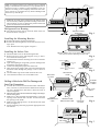
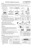
1152.6mm
45.37”
576.3mm
22.68”
752.0mm
29.6”
30mm
1.18”
30mm
1.18”
Note! The air intake grill is mounted on the bottom of the
unit. If necessary and also possible according to the installation location, it is easy to change the position of the inlet
grill to the front bottom of the unit.
972.0mm
38.26”
120.2mm
4.7”
1500 mm
59” min.
Refrigerant Line Routing
●
The refrigerant lines may be routed in either of the two
directions shown in Figure 3
INSTALLATION
PALETTE
1
Fig. 3
Installing the Mounting Bracket
●
●
Position the pattern supplied with the unit.
Position the mounting bracket on the wall and level it using a spirit
level. Dimensions as they appear in Figure 3.
Installing the Indoor Unit
●
●
●
●
●
●
●
●
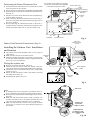
Mount the indoor unit on the mounting bracket.
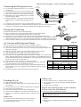
Remove the four screws which appear in Fig. 6 and remove the front bottom panel.
Attache the bottom of the unit using two screws to the wall.
(See Fig. 4).
Open the Diaphragm using knife, pass the drainage tube
through the opening (See Fig 6).
Connect the refrigerant pipe to the indoor unit.
Take out the power supply cable, inter unit cable and room
thermostat cable through the passage cover as shown in
Fig. 6).
Use the rubber rings on the cable exit from the cover.
Close the bottom front cover of the indoor unit.
FRONT VIEW: Two screws at the bottom of the
unit, must be used in attaching it to the wall.
Fig. 4
REFRIGERANT
LINES
Ø 70mm(3")
10mm(0.5")
min.
INDOOR
OUTDOOR
DRAINAGE
TUBE
ELECTRICAL
CABLE
Fig. 5
DRAINAGE
TUBE
BOTTOM
COVER
Drilling A Hole In the Wall For Drainage and
POWER
SUPPLY
CABLE
Inter-Unit Connections
●
●
●
2
4
1
3
3
INTER UNIT
CABLE
4
10
ON/STBY
OFF
ROOM
THERMOSTAT
UNIT
COVER
OPENING FOR
DRAINAGE TUBE
PASSAGE
COVER
Fig. 6
10
30
●
To make the connections between the indoor and outdoor
units, a 70 mm (3") hole should be drilled for the refrigerant lines, drainage hose and electric cables the wall, as
shown in Figure 5.
Mark the center of the hole to be drilled according to the refrigerant line routing used.
Make sure to drill outwards and downwards, so that the
opening in the outside wall is at least 10 mm lower than
the opening on the inside.
Make sure the drainage hose is at the bottom side of the
hole (see Figure 5).
Fill the remaining wall hole gap with an appropriate sealant material.
30
●
ON
OFF
300mm
11.8”
AIR VENT EXIT
RETURN
AIR VENT
1500mm
59”
STBY
300mm
11.8”
Fig. 7