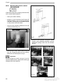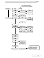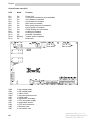
1
Saeco Group 200 Model: ESPRESSO TYPE: SG200E i OPERATION AND MAINTENANCE Hot beverage vending Machine Espresso Italia PTY LTD WARNING: This instruction manual is intended exclusively for specialized personnel. www.espressoitalia.com.au Freecall 1300 660 976 English MAIN PARTS 11 5 10 13 12 7 3 8 9 1 2 3 4 5 6 7 8 9 10 11 12 13 2 2 1 6 4 Brew group and coffee grinder Brewing hopper group Sugar and stirrer dispensing group CPU card Cup dispenser Payment system area POWER card Water circuit equipped with air-break device Pump Tray socket Data plate Data plate showing the minimum and maximum water pressure Water mains connection Espresso Italia PTY LTD www.espressoitalia.com.au Freecall 1300 660 976 English TABLE OF CONTENTS 7- PAYMENT SYSTEM INSTALLATION .................... 24 7.1 Payment system installation on the machine . ........................................... 24 Payment system installation on the cabinet ............................................... 25 7.2 1- INTRODUCTION TO THE MANUAL ............................. 4 1.1 1.2 1.3 1.4 Foreword ............................................ 4 Symbols used .................................... 4 General instructions............... ........... 5 Operator requirements ....................... 7 2- TECHNICAL SPECIFICATIONS 7 3 - SAFETY STANDARDS ............. 8 3.1 3.2 Foreword ............................................ 8 General safety rules ........................... 8 8- PROGRAMMING AND MAINTENANCE MENU ........ 26 8.1 Description of programming and maintenance phase keys Programming menu Entering the programming menu Structure of the programming menu Functions of the programming menu Maintenance menu Access to the maintenance menu Description of maintenance menu messages Software updating (machine re-programming) 8.2 8.2.1 8.2.2 8.2.3 8.3 8.3.1 8.3.2 8.4 9- 4 - HANDLING AND STORAGE .. 9 4.1 4.2 4.3 Handling and transport ...................... 9 Storage ............................................ 9 Packaging ........................................ 10 5- GENERAL TECHNICAL DESCRIPTION ..................... 10 5.1 5.2 5.3 Permitted use .................................... 10 Versions and Models .......................... 10 Basic operating concepts ................... 10 6- INSTALLATION .................... 13 6.1 6.2 6.3 6.4 6.5 6.6 6.7 6.7.1 Positioning ......................................... 13 Receipt .............................................. 14 Unpacking .......................................... 15 Water mains connection .................... 16 Electric mains connection .................. 16 Machine start-up ................................ 17 Installation ......................................... 18 Cleaning and filling of resin-based water softener .................................... 18 Water circuit filling ............................. 19 Cleaning the parts in contact with foodstuff ............................................. 20 Product loading .................................. 21 Container loading ............................... 21 Label insertion ................................... 22 Cup loading ........................................ 22 Stirrer loading ..................................... 23 6.7.2 6.7.3 6.8 6.8.1 6.8.2 6.8.3 6.8.4 27 27 27 34 34 40 40 42 45 MAINTENANCE AND INACTIVITY ......................... 46 9.1 9.1.1 9.1.2 9.1.3 9.2 9.2.1 Cleaning and loading .......................... 46 Daily cleaning .................................... 46 Weekly cleaning ................................ 48 Product loading .................................. 49 Maintenance ...................................... 49 Scheduled and unscheduled maintenance ...................................... 50 9.2.2 Brew group maintenance .................... 50 9.3 Adjustments ...................................... 51 9.3.1 Dose and grinding adjustment ............ 51 9.4 Cup releasing device cleaning and ..... adjustment ......................................... 52 9.5 Resin regeneration - where the water . softner is provided .............................. 54 10 - INACTIVITY ......................... 55 11 - DISMANTLING .................... 55 12 - TROUBLESHOOTING GUIDE FOR THE MOST COMMON FAILURES OR ERRORS ........ 56 13 - VISUAL SIGNALS (LEDs) ..... 60 Espresso Italia PTY LTD 3 www.espressoitalia.com.au Freecall 1300 660 976 English 1 - INTRODUCTION TO THE MANUAL 1.1 Foreword Important This publication is an integral part of the machine and should be read carefully in order to use it in a correct way. Complying with safety requirements is also essential This manual contains the technical information necessary to carry out the procedures of use, cleaning, installation and maintenance of the vending machine mod. SG200E correctly. Always consult this publication before carrying out any operation. Manufacturer: Saeco International Group Via Panigali, 39 - 40041 Gaggio Montano (BO). This manual should be kept with care and go with the machine throughout its operational life, also in case of changes of ownership. If this manual should be lost or worn out, it is possible to require another copy to the Manufacturer or to an Authorized Service Centre. In this event, please indicate the data on the plate located on the back of the machine. 1.2 Symbols used A number of symbols are used in this manual to classify situations according to their degree of danger, and that require technicians with different skills. The symbol is integrated with a message suggesting operating procedures or behaviours and providing useful information concerning the machine performance. 4 Warning This symbol indicates dangerous situations for the users, supply operators and maintenance technicians dealing with either the vending machine or the product to be dispensed. Important This symbol indicates operations that keep the machine in good working conditions, if properly carried out. Recommended solutions This symbol indicates the procedures that make the programming and/or maintenance operations quicker. User This symbol indicates the machine user, who is not authorized to clean or service the vending machine. Supply operator It is used to indicate operations to be exclusively carried out by personnel in charge of machine supplying and cleaning. Maintenance is exclusive task of the maintenance technician, and cannot be performed by the supply operator. Maintenance technician This symbol is used to indicate operations to be only performed by specialized maintenance personnel. The maintenance technician is the only person authorized to keep the MAIN SWITCH ACTIVATION KEY, which allows disabling the safety system. Espresso Italia PTY LTD www.espressoitalia.com.au Freecall 1300 660 976 English : Read This symbol indicates that the user should read the instruction manual carefully before operating the machine. 1.3 : General instructions Warning Before using the vending machine, read this manual carefully. A good knowledge of the information and instructions contained in this document is essential for a correct use of the vending machine, in compliance with essential safety requirements. Warning Laddetto al rifornimento non deve per alcun motivo accedere a quelle parti del distributore automatico le cui protezioni sono bloccate da mezzi che richiedano un utensile per essere liberati. For no reason whatsoever should the personnel in charge of the machine reach those parts of the machine that are protected by guards requiring special instruments for their removal. Some maintenance operations (to be carried out solely by specialised technicians) expressly require that certain safety devices be switched off. It is the buyers responsibility to ascertain that the machine operators have been trained and informed of all the indications and specifications contained in the documentation supplied. Even so, the operator should be aware of the potential risks that exist while operating the automatic vending machine. Operating reliability and the efficiency of the machine performance are guaranteed only if original spare parts are used. The user will be held entirely responsible for any modifications made on the machine. All the operations necessary to keep the machine in good working order, before and during use, are users duty. Altering and tampering with the machine without prior consent of the manufacturer, will release the latter from any liability for any damage or injury resulting from, or connected to the above modifications. This manual reflects the state of the art of the automatic vending machine at the moment of the issue on the market. Possible modifications, improvements or adjustments that are made to machines that are subsequently marketed, do not oblige the Saeco International Group either to intervene on the previously supplied machine or consider it and the relevant manual to be defective or inadequate. knowledge and absolute respect, from a technical point of view, of the safety standards and warnings contained in this manual, are fundamental for installing, using and servicing the machine under reduced risk conditions. Vending machine operator is only allowed for interventions under his own responsibility and specialization. The user should have a good knowledge of all mechanisms of the machine, as far as he is concerned. Espresso Italia PTY LTD 5 www.espressoitalia.com.au Freecall 1300 660 976 English However, the Saeco International Group, whenever necessary and for valid reasons is entitled to update existing manuals and send to his customers all updating sheets that have to be kept with the original manual. Any technical problems that may arise can easily be solved by consulting this manual. For further information, contact the dealer where the machine was purchased, or one of the authorized service centres. When calling, please, provide the following information: - the data written on the data plate located on the rear side of the vending machine (fig. 1) Data Plate - The card code and version, to be found on the component side of the CPU card (ref.2, fig. 2). Warning It is absolutely forbidden to tamper with or modify the data plate. The Saeco International Group declines all responsibility for injuries to people or damage to things resulting from: - incorrect installation - inappropriate electrical and/or water connection - inadequate cleaning and maintenance - unauthorized modification - improper use of the vending machine - non-original spare parts The Saeco International Group will not be obliged in any case to indemnify any damage caused as a result of the forced inactivity of the machine due to failure. Installation and maintenance must be only carried out by qualified technicians. fig. 1 - The program version in the microprocessor (see adhesive label on the component mounted on the CPU card) (ref.1, fig. 2). 1 Use only specific foodstuffs suitable for vending machines. The automatic vending machine is not suitable for outside installation. The machine must be installed in dry places, with temperatures not below 1°C and it must not be installed in places where cleaning is made with water hoses (e.g. large kitchens, etc.). If at the time of installation, the usage conditions are different from those established or are subject to change over time, please contact the manufacturer immediately before using the machine. Furthermore, always act in compliance with national or local standards. fig. 2 6 Espresso Italia PTY LTD www.espressoitalia.com.au Freecall 1300 660 976 English 1.4 Operators requirements To guarantee safety, three different machine users are to be distinguished, each having specific characteristics: User 2 - TECHNICAL SPECIFICATIONS Weight Overall dimensions 40 Kg See fig. 3 Access to the inside of the machine is forbidden to the user. Supply operator 759.5 The safekeeping of the access key to the inside of the machine is entrusted to the Supply operator by the Maintenance Technician. He has the task of supplying the products, external cleaning, activating and stopping the machine. Warning The Supply Operator is not authorized to carry out operations that are indicated as competence of the Maintenance technician in this publication. Maintenance technician Is the only person authorized to carry out and start programming procedures for adjusting, setting up and upkeep the machine. 537.8 410 fig. 3 Power consumption see Data plate (fig. 1) Mains voltage: see Data plate (fig. 1) Electric voltage frequency. see Data plate (fig. 1) Power cord length 1,600 mm Connection to water mains 3/8 gas type Water system pressure: from 1.5 up to 8 bar (fig. 4) A-Weighted sound pressure level: lower than 70 db Espresso Italia PTY LTD 7 www.espressoitalia.com.au Freecall 1300 660 976 English Data plate showing the minimum and maximum water pressure 3 - SAFETY STANDARDS 3.1 In compliance with the Machine Directive 98/37/ EEC, Low Tension Directive 73/23/EEC and CE Marking Directive 93/68/EEC, the Saeco International Group has drawn up a technical file on D.A. SG200 E vending machine at its plants, acknowledging during the design phase the regulations listed in the Declaration of Conformity inside any vending machine. fig. 4 CUP DISPENSER suitable for cups with 70-71 mm dia. and for cups with 73 mm dia. through an adequate release ring. BOILER HEATING ELEMENTS armoured types: from 1,000 Watt for coffee boiler CONTAINER CAPACITY Coffee beans Instant coffee Granular milk Chocolate Tea Sugar Cups Stirrers Foreword 2.0 Kg 0.6 Kg (instead of tea) 0.85 Kg 1.7 Kg (or 2.6) 2.0 Kg 2.0 Kg 195 185 3.2 General safety rules Warning - Before using the vending machine, read this manual carefully. - Installation and maintenance must only be carried out by qualified technicians. - For no reason whatsoever shall the operator reach those parts of the machine that are protected by guards requiring special instruments for removal. - Good knowledge and absolute respect, from a technical point of view, of the safety standards and danger warnings contained in this manual, are imperative for installing, using, servicing and maintaining the machine in minimum minimum risk conditions. Warning Always disconnect the POWER CABLE before servicing or cleaning the machine. Under no circumstances neither service the machine, nor remove safety guards before hot parts have cooled down! 8 Espresso Italia PTY LTD www.espressoitalia.com.au Freecall 1300 660 976 English - Operating reliability and the efficiency of the machine performance are only guaranteed if original spare parts are used. - The automatic vending machine is not suitable for outside installation. The machine must be installed in dry places, with temperatures never below 1°C and it must not be installed in places where cleaning is made with water hoses (e.g. large kitchens, etc). - In order to guarantee the performance of the machine, always keep the automatic vending machine in perfect cleaning conditions. - The Saeco International Group declines all responsibility for injuries to people or damage to things as a consequence of: - Use individual protection devices during installation, testing and maintenance. incorrect installation inappropriate electrical and/or water connection inadequate cleaning and maintenance unauthorized modification improper use of the vending machine non-original spare parts Important It is forbidden to: - Tamper with or cut off the safety systems installed on the vending machine; - Use water jets to clean the machine. Furthermore, always act in compliance with national or local standards. 4- HANDLING AND STORAGE 4.1 Handling and transport The transport of the vending machine should be carried out by skilled personnel. The vending machine is delivered on a pallet; for handling purposes use a fork lift truck and move it slowly in order to avoid any possible overturning or dangerous oscillations. Important Avoid: - lifting the vending machine with ropes or presses; - dragging the vending machine - turning over or laying down the vending machine during transport - shaking the vending machine Avoid the machine: - being bumped into being overloaded with other parcels being exposed to rain, frost or heat sources being kept in damp places 4.2 Storage In the event of storage, avoid any stacking of several machines, keep them in a vertical position, in dry places with temperatures not below 1°C. Espresso Italia PTY LTD 9 www.espressoitalia.com.au Freecall 1300 660 976 English 4.3 Packaging The vending machine is protected by polystyrene/cardboard angles and by a transparent polypropylene film. The automatic vending machine will be packaged so as to ensure protection against any mechanical and environmental agents. Labels are applied on the packaging, indicating: - handle with care do not overturn protect from rain do not stack protect from heat sources not shock resistant machine type and serial number Important Once the transport is over, the packaging should be undamaged, which means it should not: 5- GENERAL TECHNICAL DESCRIPTION 5.1 The vending machine is to be used exclusively for the dispensing of beverages, prepared by mixing foodstuffs with water (by brewing, as to coffee). To this purpose, use products that the manufacturer has declared as being suitable for vending in open containers. Beverages are brewed in suitable plastic cups, which the machine dispenses automatically. The stirrer used for mixing sugar is automatically dispensed. Beverage should be drunk at once and under no circumstances can they be kept for subsequent consumption. 5.2 - show any crushed parts, sign of shocks, buckling or breaking - show wet parts or signs that could lead to suppose its exposure to rain, frost or heat - show signs of tampering Permitted use Versions and models Warning: This manual refers to the top-of-the -range model: it is therefore possible to find descriptions or explanations not relating to the machine you have. 5.3 Basic operating concepts During normal operation, the vending machine is in standby mode. By introducing the amount corresponding to the price displayed and by pressing the key relevant to the desired beverage, you will start the dispensing cycle. This one basically consists of: BEVERAGE SELECTION The machine can dispense 8 beverages. A beverage can be selected according to the following conditions: the vending machine has reached the set temperature after start-up. Otherwise, once a key is pressed, the display shows the message PLEASE WAIT. 10 Espresso Italia PTY LTD www.espressoitalia.com.au Freecall 1300 660 976 English the available credit is sufficient or the vending machine has been set in free mode. If this is not the case, the display shows the message INSERT ...; there is no error condition that prevents beverage brewing. If it is not the case the display shows the error message BEVERAGE... OUT OF SERVICE alternated to a NOT AVAILABLE message; the selected beverage has been enabled. If this is not the case, the message NOT AVAILABLE will be displayed; the selected beverage is not prevented. Otherwise, before pressing the key, the message BEVERAGE ... alternated to a NOT AVAILABLE message is displayed. After pressing the key, the display shows NOT AVAILABLE; During hot beverage brewing: - payment systems are disabled; - the first line on the display shows the programmable dispensing message (default message is: WAIT FOR PRODUCT). Beverage selection If the vending machine has not been programmed to freely dispense beverages insert the required credit Press the key corresponding to the beverage requested. After beverage dispensing, the message REMOVE CUP is displayed. Take the beverage from the dispensing outlet. Warning Not to burn your hand, wait for the signal REMOVE CUP- before introducing your hand. Do not open the dispensing outlet door while the VM is brewing. In case of failures or product missing during the brewing phase, the display indicates the causes. CUP, SUGAR AND STIRRER DISPENSING This is the first operation that the vending machine activates (except for without cup dispensing selection): the cup bracket motor is activated and moves under the cup chute. At the same time, it operates the cup scrolls to separate the first cup and let it drop into the special support fork. The same motor draws the cup under the sugar dispenser there it stops for 2 seconds. In this way dispensing is enabled and, where it is set or required, a stirrer is dispensed. Finally, it sets the cup under the beverage brewing nozzles. The stirrer dispensing is controlled through a solenoid which actuates the stirrer ejector. The stirrer is then dropped into the cup by means of the proper chute. When selecting a beverage, sugar is dosed through a motor that activates the sugar hopper screw. INSTANT BEVERAGE BREWING This process takes place after dispensing of cup, sugar and stirrer. According to the type of beverage selected and machine model, the following processes are activated. If present, the motor mixer starts. the instant product solenoid valve (ref.1' fig.5), located on the coffee boiler, starts and allows to fill the mixer with the preset amount of water. The pump (ref.2' fig.5) is then activated and the preset amount of water dispensed, under the control of an appropriate electronic device (volumetric meter) (ref.3' fig.5). Espresso Italia PTY LTD 11 www.espressoitalia.com.au Freecall 1300 660 976 English 1 2 the unit rotation gear motor activates, thus moving the unit to the brewing position. The coffee tablet is pressed simultaneously. the pump brewing the set quantity of water activates, under the control of an appropriate electronic device (volumetric meter) (ref. 3 fig. 5). the brew group gear motor is restarted, and goes back to the rest position. During this movement the coffee tablet is ejected. The grinder and dosing unit activation sequence can take place in reverse order, according to the program selected (see programming menu). 3 fig. 5 the gear motor of the instant product activates the screw, dispensing the desired amount of product into the mixer. once the pre-set amount of water and product is dispensed, the mixer is disconnected. ESPRESSO COFFEE BREWING This process takes place only after the dispensing of cup, sugar and stirrer. the grinder (ref.1 fig.6) is activated until the quantity of coffee set on the dosing unit (ref.2 fig.6) is reached the activation of the dosing unit solenoid (ref. 3 fig. 6) causes the door to open and, as a consequence, the coffee is dispensed into the cup. 1 3 2 fig. 6 12 Espresso Italia PTY LTD www.espressoitalia.com.au Freecall 1300 660 976 English 6 - INSTALLATION 6.1 Positioning The vending machine is not suitable for outdoor installation. It must be installed in dry places, with temperatures not below 1°C and it should not be installed in places subject to explosion or fire hazards, or where cleaning is done with water jets. - If positioned near a wall, there must be a minimum distance of at least 5 cm from the wall (fig. 7), so as to allow regular ventilation. Under no circumstances cover the vending machine with cloths or similar. fig.7 Espresso Italia PTY LTD 13 www.espressoitalia.com.au Freecall 1300 660 976 English - When positioning the vending machine, check its levelling by means of the adjustable feet already fitted under the vending housing (fig. 8) or under the cabinet (fig. 9) Make sure that the vending machine does not have an inclination exceeding 2 degrees. 6.2 Receipt Upon receipt of the automatic vending machine, it is necessary to check it has not suffered damage during transport. If damage of any kind is noticed, immediately place a claim with the forwarder. An envelope is supplied with the vending machine, called CUSTOMER KIT. It contains the objects shown in Fig. 10. fig.8 - Instruction manual. - Powder tank plates and prices in euro. - Push-button panel selection plates. - Instruction plates. - Wiring and hydraulic diagram. - Power cord. - Safety switch key (Technical engineer). - Declaration of conformity fig. 9 The Saeco International Group declines all responsibility for troubles due to the failure in observing the assembly rules. If installation takes place in safety evacuation corridors, make sure that the machine with the door open assure sufficient space for people to pass by (fig. 7). In order to avoid the floor from getting dirty as a result of accidental spillage of products, place a sufficiently wide protection to cover the working area under the vending machine. 14 fig. 10 Espresso Italia PTY LTD www.espressoitalia.com.au Freecall 1300 660 976 English 6.3 Unpacking - Free the vending machine from the package. - Remove the vending machine from the transport pallet. Unloose its fastening screws (fig. 11). Open the door of the vending machine and remove the adhesive tape from the components concerned. - Remove polystyrene securing internal components (fig. 13) Warning: The packing material must not be accessible to unauthorized people, as it is a potential source of danger. For the disposal please contact qualified companies. fig.13 fig.11 - Remove the key from the beverage dispensing outlet (fig. 12). fig.12 Espresso Italia PTY LTD 15 www.espressoitalia.com.au Freecall 1300 660 976 English 6.4 Water system connection Before connecting the vending machine to the water mains, make sure that the water is: - drinkable, if necessary by means of a test laboratory certification - has a pressure ranging between 1.5 and 8 bar, otherwise use a pump or a water pressure reducer accordingly. - if not already fitted, install a tap in an accessible position, so as to separate the equipment from the water mains, should it be necessary (fig. 14). - connect the tap to the vending machine, using a copper or nylon hose, suitable for foodstuff and resistant to the supply pressure. Should a flexible hose be used, it is necessary to assemble the reinforcement bearing inside, supplied with the machine. - Use a 3/8 gas-type connection. 6.5 Power supply connection The veding mahine is designed to operate with single phase voltage at 230 Volts and is protected by 6,3 A delay fuses. We suggest checking the following: - the mains voltage of 230 V should not exceed a ± 6% fluctuation - the power supply is suitable to the machine - a differential protection system is connected The machine should be earthed in observance with operating safety rules in force. For this reason, verify the system earth wire connection to ascertain that it is efficient and in compliance with national and European electric safety standards. fig.14 - let some water flow out of the tap in order to eliminate possible traces of impurities and dirt (fig.15). fig.15 16 If necessary, have the system inspected by qualified personnel. - The machine is equipped with power cord (fig.16) fig.16 Espresso Italia PTY LTD www.espressoitalia.com.au Freecall 1300 660 976 English - The sockets that are not compatible with the plug of the machine should be replaced. - The use of extensions, adapters and/or multiple plugs is forbidden (fig 17). Warning During the setting-up phase, before powering up the machine, make sure you have connected it to the hydraulic system and opened the water tap. Warning The safety switch remains live (ref. 1, fig. 18) - For some operations, it is however necessary to operate with the door open but the vending machine connected to the mains. fig.17 6.6 Machine start-up The machine is equipped with a safety switch located on its top cover (fig. 18) which disconnects the utilities whenever the door is opened (see wiring diagram). Therefore, open the door or unplug the installation in case of need. Safety switch Skilled technicians may operate in this way, by inserting the special plastic key, supplied with the machine, into the switch located on the machine top cover, turning it of 90° (fig. 18). Warning The opening and possible machine start with door open must only be performed by authorized and technically qualified personnel. Do not leave the machine unattended while it is open. Give the key to qualified and authorized personnel only. Whenever the machine is switched on a test cycle is performed in order to verify the correct position of the moving parts and the presence of water and other products. fig.18 Espresso Italia PTY LTD 17 www.espressoitalia.com.au Freecall 1300 660 976 English 6.7 Installation - fill up the water softener and let the water flow out of the drain hose until it is clear (fig.20). IMPORTANT: When switched on, the machine automatically fills the water circuit and the related boilers. For a correct automatic installation in case of a water softener system being used, it is necessary that the latter is completely filled with water and properly relieved of any air bubbles. 6.7.1 Cleaning and filling of resinbased water softener IMPORTANT: Before installing the water softener in the machine and using it, clean the resins and fill the water softener. Then install the water softener already filled with water and cleaned. In order to fill in the water softener before installing it on the machine, stick to the following instructions: fig.20 - close upper plug and turn off the bottom tap - Insert the hose of the bottom tap into a drain container suitable for this purpose. - open the bottom tap (fig. 19) and the upper plug of the water softener so as to remove the air bubble. fig.19 18 Espresso Italia PTY LTD www.espressoitalia.com.au Freecall 1300 660 976 English 6.7.2 Water circuit filling The machine automatically activates the pump and starts filling the espresso coffee boiler. IMPORTANT: Before powering the machine, thus starting the automatic installation: 1. Make sure that the water softener is filled with water and the air bubbles removed. 2. Load the reachable columns of the cup holder. NOTE: If the filling of the boiler is not successful, the machine cannot be set into service. A failure message will be shown on the display. Should it be the case, eliminate the cause and reset the error recorded (section 8 Programming and maintenance menu), then repeat the automatic installation, switching the machine on once again. After a testing phase on start-up, the machine automatically fills the water circuit of the tray equipped with a float and of the brew group boiler. During this stage, the heating element of the boiler remains automatically off. If the machine detects that the boiler is already filled, it passes to the heating stage. During the setting-up phase: - the coffee boiler and the water tank are filled up - once the water circuit is filled, the heating phase starts up, thus switching on automatically the boiler heating element. Recommended solutions When the boiler is completely filled, wash the mixer repeatedly in order to remove possible residues from the hydraulic circuits. NB: see section 8 - Programming and Maintenance menu, in order to start test or cleaning brewing. - After performing these operations, wait a few minutes for the machine to reach service temperature and make beverages available. The sequence of operations will be: - insert the special key in the machine cover switch - on start-up of the machine, the filling of the tray equipped with a float starts automatically, while the machine carries out the automatic testing phase. During testing, the following components start up in the given order: - the brew group, so as to reach the correct start-up position - the cup holder, so as to load the first cup column into the releasing device. Espresso Italia PTY LTD 19 www.espressoitalia.com.au Freecall 1300 660 976 English 6.7.3 Cleaning the parts in contact with foodstuffs Clean all the parts of the vending machine which are in contact with foodstuffs. - wash your hands carefully. - prepare a chlorine-based anti-bacterial cleaning solution - they can be purchased at chemists - following the concentrations given on the product instruction label. - remove all the product containers from the vending machine (fig. 21). fig.22 - remove all the powder conveyors, water funnels, mixer chambers and fans, silicone hoses and plunge them into the solution (fig.23). fig.21 - remove their covers, bushes and conveyors (fig. 22). Plunge all parts into the solution, apart from the steel spiral conveyor. Important Do not plunge the spiral conveyor into the chlorine-based solution; clean it with washing up detergent and rinse carefully. fig.23 20 Espresso Italia PTY LTD www.espressoitalia.com.au Freecall 1300 660 976 English - clean also the mixer bases with a cloth soaked in the solution (fig.24) fig.25 - lift the container cover and fill with the product. fig.24 - leave all parts in the solution for the time specified on the packaging - take all parts off, rinse and wipe carefully, then reassemble them into the vending machine. Warning - make sure there is no lump, avoid pressing the product and using too much of it, so as to prevent it from ageing. It is advisable to fill the containers with the exact amount of product necessary for the estimated consumption between two consecutive refillings. Check each container capacity in the TECHNICAL SPECIFICATIONS section. For safetys sake, carry out several automatic washings so as to remove possible residues. 6.8 Product loading 6.8.1 Container loading - product containers can be loaded without removing them; however, should it be necessary to remove them, make sure the sliding panel on the product outlet is closed (fig.25). In particular, it is necessary to close the panel located on the hopper before removing the coffee bean container. NB:containers can also be loaded without removing them from their supports fig.26 Warning - For correct operation of the swivelling conveyor follow the indications below: before starting up, brew the product 3 - 4 times so as to have the duct full (fig.26) - After filling up the sugar container, make sure the bracket is properly repositioned - the jack on the side is supposed to click. Espresso Italia PTY LTD 21 www.espressoitalia.com.au Freecall 1300 660 976 English 6.8.2 Label insertion - Selection labels are to be placed in the proper seat, under the transparent plastic plates, following the order set in the Programming and Maintenance Menu. Perform the operation as follows: - remove the cup holder (fig. 27) fig.29/30 - reassemble the cup holder 6.8.3 Cup loading Use only cups suitable for automatic distribution, having 70-71 mm diameter, without pressing them while loading. Important fig.27 - release the transparent plates from the internal side of the door by pressing the retaining tabs (fig.28) DO NOT ATTEMPT TO TURN THE COULUMN MANUALLY. During installation, with the cup dispenser empty, proceed as follows: - before powering up the vending machine, load the most easy-to-reach columns (fig. 31). fig.28 - insert product plates on the external side of the door in the desired order (fig. 29) - apply the transparent plates by snapping them (fig.30) 22 fig.31 Espresso Italia PTY LTD www.espressoitalia.com.au Freecall 1300 660 976 English - insert the key into the cover switch (see fig.18) and wait for the column to position itself into the dispensing hole. - Introduce stirrers tightened with the band into the column; once they are on the bottom, cut the band and remove it (fig.34) - load the other two columns which in the meantime have become reachable (fig.31). - if you want to fill up the column near the cup conveyor, remove the holder retainer (fig.32 ref. 1) and lean the whole cup dispenser as much as permitted (fig.32 ref. 2), complete the cup column loading and then put back the dispenser and the retainer. 1 2 fig.32 fig.34 - replace the cover on the container. 6.8.4 - put back the counterbalance bar (fig.35) after completing the loading Stirrer loading - Remove the counterbalance bar from the stirrer guides (fig.33) fig.35 fig.33 - make sure stirrers have no seams, are not bent and all lay horizontally. Espresso Italia PTY LTD 23 www.espressoitalia.com.au Freecall 1300 660 976 English 7 - PAYMENT SYSTEM INSTALLATION 7.1 Payment system installation on the machine The vending machine has no payment system. The responsibility for possible damages to the machine and other objects and for personal injuries caused by an incorrect installation of the payment system falls on the person who installed the system. - remove the cup dispenser - from the internal side of the door, cut the external film following the punched shape which corresponds to the desired cashless payment or coin validation system (fig. 36) fig.37 - after finishing the whole perimeter, install and secure the payment system - connect the payment system to the CPU card - reassemble the cup dispenser NOTE: a special interface card is required for connecting 12 Vcd coins validation systems to the CPU card. - Then enter programming so as to choose convenient settings. See section 8 PROGRAMMING AND MAINTENANCE MENU in order to check parameter setting, which should be in line with the system used. fig.36 - cut away plastic door joints by means of an hacksaw (fig.37) 24 Espresso Italia PTY LTD www.espressoitalia.com.au Freecall 1300 660 976 English 7.2 - connect the coiner to the CPU card Payment system installation on the base cabinet The base cabinet has no payment system. The responsibility for possible damages to the machine and other objects and for personal injuries caused by an incorrect installation of the payment system falls on the person who installed the system. - remove or turn the coiner supporting plate (fig.38, ref.1) NOTE: Executive, MDB and BDV serial systems are connected to the CPU card using a cable and an interface in necessary, both included in the special kit. - Then enter the programming menu so as to choose convenient settings. See section 8 PROGRAMMING AND MAINTENANCE MENU in order to check parameter setting, which should be in line with the system used. - hook and secure the coiner to the support (fig.38, ref.2) - reassemble and lock the support to the cabinet door (fig.38, ref.3) fig.38, rif.1 fig.38, rif.2 fig.38, rif.3 fig.38 Espresso Italia PTY LTD 25 www.espressoitalia.com.au Freecall 1300 660 976 English 8- PROGRAMMING AND MAINTENANCE MENU Important This chapter illustrates how to set up or modify the machine programming and maintenance parameters. It should therefore be read carefully, to fully understand the correct sequence of operations to be performed. Important Fig. 39 shows the standard position of keys on the door keypad; to which all the following sections will refer to. Key ñ: UP Key ò:DOWN Key c: CANCEL / beverage 01 Key e: ENTER / beverage 05 beverage 02 beverage 06 beverage 03 beverage 07 beverage 04 beverage 08 fig.39 26 Espresso Italia PTY LTD www.espressoitalia.com.au Freecall 1300 660 976 English 8.1 Description of programming and maintenance phase keys To surf inside the menu of the vending machine use the keys described below. Key e: ENTER / beverage 05 (fig. 39) By pressing this key it is possible to access the following level of programming or maintenance. Furthermore it is possible to modify or confirm the values set in the entries of the programming or maintenance menus. Key c: CANCEL /beverage 01 (fig. 39) By pressing this key it is possible to go back to the previous level of the programming or maintenance menu. It is also possible to avoid storing the values of the previously required modification. 8.2.1 Entering the programming menu Open the door, insert the key into the safety switch (fig.18) and press key P1, located on the CPU card (fig.40, ref. 1) so as to enter the programming menu. 1 2 3 Key ò: DOWN / - sugar (fig. 39) By pressing this key it is possible to access the preceding entry inside the same menu level. If used after requesting to modify a datum, it decreases its value of this same datum. Key ñ: UP / - sugar (fig. 39) By pressing this key it is possible to access the following entry inside the same menu level. If used after requesting to modify a datum, it increases the value of this same datum. 8.2 Programming menu The structure of the programming menu is shown in 8.2.2. 8.2.3 describes all the entries in the programming menu. fig.40 If no password has been assigned you enter the programming menu directly. Important If a password to enable the programming menu was assigned to the vending machine, PASSWORD 0000 will appear on display with a flashing cursor on the first digit. Now enter the password using UP and DOWN keys. Confirm the digit entered pressing the ENTER key. To exit the programming menu and return to the normal operation of the vending machine: - press key P1 again; - remove the key from the safety switch to turn off the vending machine; - close the door and wait for the selfconfiguration process to end. Espresso Italia PTY LTD 27 www.espressoitalia.com.au Freecall 1300 660 976 English SYSTEM MANAGEMENT VM CODE 0000 STOP VM CODE >0000< STOP COFFEE 00000 LIM:00321 With complete menu only BEVERAGE A 00000 LIM. 000111 STOP BEVERAGE STOP GROUNDS 00000 LIM:0090 With complete menu only RESET RESET >Y< N BEVERAGE 00000 B LIM. 000222 BEVERAGE 00000 C LIM. 000333 BEVERAGE 00000 D LIM. 000444 BEVERAGE 00000 E LIM. 000555 BEVERAGE 00000 F LIM. 000666 MINIMUM TEMPERATURE 098 MINIMUM TEMPERATURE > 096 < BEVERAGE 00000 G LIM. 000777 MAXIMUM TEMPERATURE 108 MAXIMUM TEMPERATURE > 110 < BEVERAGE 00000 H LIM. 000888 RINSING CYCLE NO RINSING CYCLE Y >N< PRE-GRINDING NO PRE-GRINDING >Y< N INSTANT PRODUCT PREHEAT. TIME-KEEPER 12:12 M 20 SEPT 00 BEVERAGE 00000 INSTANT PRODUCT 1 0 INSTANT PRODUCT 1 >20< INSTANT PRODUCT 3 0 INSTANT PRODUCT 3 >20< I LIM. 000999 TIME-KEEPER 12:12 M 21 SEPT 00 CONTINUES With time-keeper and complete menu only 28 Espresso Italia PTY LTD www.espressoitalia.com.au Freecall 1300 660 976 English SYSTEM MANAGEMENT BEVERAGE PULSE COUNTER BEVERAGE PULSE COUNTER COFFEE PULSE COUNTER TEXT STAND-BY *SAECO GROUP 200* TEXT STAND-BY SAECO GROUP TEXT DISPENSING WAIT FOR PRODUCT TEXT DISPENSING BREWING... TEXT PRESELECTION PRESELECTION TEXT PRESELECTION PRESELECTION TEXT OUT OF SERVICE CALL ASSISTANCE TEXT OUT OF SERVICE CALL ASSISTANCE STIRRER ALWAYS STIRRER ALWAYS With complete menu only With the option Instant key = preselection only STIRRER SUGAR STIRRER SUGAR OR WTHOUT SUGAR INSTANT KEY BEVERAGE 01 INSTANT KEY PRESELECTION CONTINUES INSTANT KEY DISABLED With complete menu only INSTANT KEY BEVERAGE 01 Espresso Italia PTY LTD 29 www.espressoitalia.com.au Freecall 1300 660 976 English SYSTEM MANAGEMENT INSTANT PRODUCT 1 YES INSTANT PRODUCT 1 >Y< N INSTANT PRODUCT 3 NO INSTANT PRODUCT 1 >Y< N MULTIPLE BEVERAGE 02 MULTIPLE BEVERAGE 02 MULTIPLE BEVERAGE ON/off: ABCdefGHI BEVERAGE VALIDATION BEVERAGE 01 YES PRODUCT BEFORE NO BEVERAGE 15 YES complete menus only FREE VEND BUTTON YES FREE VEND BUTTON >Y< N NO CUP BEVERAGE 05 NO CUP >DISABLED< AUTOMATIC CUP YES NO CUP PRESELECTION AUTOMATIC CUP >Y< N NO CUP BEVERAGE 05 RESET VALIDATION YES LANGUAGE ITALIANO RESET VALIDATION >Y< N LANGUAGE ITALIANO LANGUAGE ENGLISH LANGUAGE FRANCAIS MODIFY PASSWORD 0001 COMPLETE MENU NO COMPLETE MENU >Y< N With complete menu only CONTINUES MODIFY PASSWORD 0000 30 Espresso Italia PTY LTD www.espressoitalia.com.au Freecall 1300 660 976 English PAYMENT SYSTEMS PARALLEL COINER ENABLE YES ENABLE >Y< N COIN VALUE COIN 01: 50 COIN VALUE COIN 07: 50 BANKNOTE READER ENABLE YES INHIBITION LEVEL 0 ENABLE >Y< N INHIBITION LEVEL >0< 1 BANKNOTE VALUE BANKNOTE 01: 1000 BANKNOTE VALUE BANKNOTE 04: 1000 SAECO CARD PROTOCOL RECHARGE YES RECHARGE >Y< N CARD PRICES YES CARD PRICES >Y< N MAX CARD LOAD 60000 MAX CARD LOAD 65000 REJECT CARD 70000 REJECT CARD 65000 FREE CARD YES FREE CARD >Y< N EXECUTIVE PROTOCOL EXECUTIVE PROTOCOL With Saeco Card only PRICE HOLDING PROTOCOL PROTOCOLLO BDV MDB PROTOCOL NO PROTOCOL PROTOCOL MDB SLAVE PROTOCOL EXEC MASTER/SLAVE PROTOCOL CONTINUES MULTIVEND YES MULTIVEND >Y< N OVERPAY TIME 100 OVERPAY TIME 120 NATION CODE 0039 NATION CODE 0042 SCALE FACTOR 10 POINT POSITION 0000 With complete menu only SCALE FACTOR 1 POINT POSITION 00.00 Espresso Italia PTY LTD 31 www.espressoitalia.com.au Freecall 1300 660 976 English BEVERAGE BREWING BEVERAGE BREWING BEVERAGE 1 BEVERAGE 1 SEQUENCE 003C BEVERAGE BREWING BEVERAGE 2 BEVERAGE 1 INSTANT PROD. 3: 005 BEVERAGE 1 WATER INST. PROD. 3: 022 BEVERAGE BREWING BEVERAGE 8 BEVERAGE 1 WATER COFFEE: 38 BEVERAGE BREWING BEVERAGE 9 BEVERAGE BREWING BEVERAGE 10 BEVERAGE 1 SUGAR: 0 With INSTANT KEY= PRESELECTION BEVERAGE 1 BEVERAGE CHECK BEVERAGE 1 PRESS KEY SINGLE PRICE YES SINGLE PRICE >Y< N BEVERAGE BREWING BEVERAGE 16 PRICE MANAGEMENT PRICE TABLE PRICE TABLE PRICE 001: 50 PRICE TABLE PRICE 002: 250 PRICE TABLE PRICE nnn: 550 BEVERAGE PRICES BEVERAGE PRICES NORMAL IMPOSTAZIONE SINGLE PRICE GLOBALE 001: 200 INDIVIDUAL PRICE BEVERAGE PRICE A 001: 200 BEVERAGE PRICE A 001: 200 SINGLE PRICE YES BEVERAGE PRICES DIFF. 1 BEVERAGE PRICES DIFF. 1 IMPOSTAZIONE SINGLE PRICE GLOBALE 001: 200 INDIVIDUAL PRICE With time-keeper only CONTINUES BEVERAGE PRICES SAECO CARD 32 CUP PRICE 50 SINGLE PRICE >Y< N BEVERAGE PRICE A 001: 200 BEVERAGE PRICE A 001: 200 With Card Prices enabled only CUP PRICE 001: 200 Espresso Italia PTY LTD www.espressoitalia.com.au Freecall 1300 660 976 English TIMETABLE SETTING NEVER FREE NEVER FREE ALWAYS FREE FREE TIME RANGE FREE ON1: MTWtfss 00:15 FREE OFF1: MTWtfss 07:15 With time-keeper and complete menu only FREE ON2: mtwTFss 19:15 FREE OFF2: mtwTFss 20:15 TIMETABLE SETTING TIMETABLE ON/OFF YES TIMETABLE ON/OFF >Y< N TIMETABLE ON/OFF ON1: MTWtfss 00:15 TIMETABLE ON/OFF OFF1: MTWtfss 07:15 With time-keeper and complete menu only TIMETABLE ON/OFF ON2: mtwTFss 19:15 TIMETABLE ON/OFF OFF2: mtwTFss 20:15 DIFF. 1 NO DIFF. 1 >Y< N DIFF. 1 ON1: MTWtfss 00:15 DIFF. 1 OFF1: MTWtfss 07:15 DIFF. 1 ON2: mtwTFss 19:15 DIFF. 1 OFF2: mtwTFss 20:15 DIFF. 2 NO DIFF. 2 >Y< N DIFF. 2 ON1: MTWtfss 00:15 DIFF. 2 OFF1: MTWtfss 07:15 DIFF. 2 ON2: mtwTFss 19:15 DIFF. 2 OFF2: mtwTFss 20:15 SYSTEM MANAGEMENT RINSING NO RINSING >Y< N RINSING ON1: MTWtfss 00:15 With time-keeper only RINSING ON2: MtwTFss 19:15 Espresso Italia PTY LTD 33 www.espressoitalia.com.au Freecall 1300 660 976 English 8.2.2 Structure of the programming menu Example of parameter setting To set the PRICE level 3 at 0.3 : - access the programming menu as indicated in 8.2.1, if the password is not requested, the entry SYSTEM MANAGEMENT will appear; - scroll the menu items with the UP key until PRICE MANAGEMENT is displayed; - press the ENTER key until the following message is displayed: PRICE TABLE - scroll the menu items with the UP key until the following message is displayed: PRICE 03 - press the ENTER key (the cursor on the value to be modified will flash); - increase or reduce the value with the UP and/ or DOWN keys until reaching 0.3 and press the ENTER key to confirm the value desired the cursor disappears. 8.2.3 Functions of the programming menu SYSTEM MANAGEMENT The entries of the SYSTEM MANAGEMENT are: Vending Machine Code It allows you to assign an identification code for the vending machine. Stops It allows you to set the maximum amount of beverage or coffee. Once reached the maximum amount, the vending machine stops the brewing of relevant beverages. The first digit on the left (00000) refers to the quantity of the product dispensed from the last RESET (partial counters reset). The left hand digit, preceded by LIM, shows the maximum dispensable quantity (changeable value). 34 - Stop coffee It allows to set the maximum number of coffee cups to be brewed before the stop. - Stop beverage It allows you to set the maximum number of individual beverages to be brewed before the stop. - Stop grounds It allows you to set the maximum number of coffee cups to be brewed, corresponding to maximum dump box capacity. Once reached the set quantity, coffee-based beverages dispensing is stopped. The display shows the blinking message REMOVE DUMPS before brewing the last ten coffees. Important This stop can be reset by removing the dump box for at least 5 sec. Recommended solutions It is advisable to set a max. of 100 coffees when using the dump box supplied with the machine Important Do not set any stop value if you are using the machine together with the supporting cabinet, which is equipped with its own dump box which is not controlled electronically - Reset It allows you to reset partial counters of stop functions. - Minimum temperature It allows you to set the temperature that the vending machine keeps for a few minutes after a beverage has been brewed. Set value is not expressed in centigrade. Espresso Italia PTY LTD www.espressoitalia.com.au Freecall 1300 660 976 English - Maximum temperature It allows you to assign the temperature to which the vending machine is brought after a certain time from the last dispensing, so that the natural lowering of the temperature of the hydraulic circuits can be compensated. Set value is not expressed in centigrade. - Wash cycle It enables starting the mixing bowls automatic wash. The automatic wash is performed as follows: the first wash take place 10 minutes after the machine ready status; if necessary, other washes occur 7 hours after the last brewing. Recommended solutions Automatic washes should be set only if the machine is used together with the cabinet, which is equipped with a large discharge fluid thank. - Pre-grinding It validates instant pre-grinding of the coffee dose - Instant product preheating It allows enabling preheating only for selected products. PREHEAT. SOLUBLES SOLUBLE 1 10 SOLUBLE 2 0 By validating this function the vending machine execute a preliminary water brewing through the circuit corresponding to the selected instant product. The user can choose the instant products for which to validate the prewash by setting a value >0 for the water to be used for prewashing. Example: the settings shown in the figure validate preheating for instant product 1 with 10 units of water and do not validate preheating for instant product 2. Preheating for an instant product is executed if: at least 3 minutes have passed since the mixing bowl was used; the amount of water for the instant product is < 50 units. Recommended solutions Instant product preheating should be set only if the machine is used together with the cabinet, which is equipped with a large discharge fluid thank. - Clock (shown only if the clock module has been installed) It allows you to set current hours, minutes, day of the week, day of the month, month and year. - Coffee / beverage pulse counter - shown only if the complete menus option is validated The electromechanical pulse counter 24V dc (option) allows to choose whether to count only coffee or all the beverages brewed. - Text: Stand-by It allows you to enter the message displayed when the vending machine is in normal operating mode. - Text: Dispensing It allows you to set the message displayed when the vending machine is brewing a product. - Text: Out of Service It allows you to set the message displayed when the vending machine stops for a failure. - Text: Preselection It allows you to set the message displayed when the preselection mode is activated. Espresso Italia PTY LTD 35 www.espressoitalia.com.au Freecall 1300 660 976 English - Stirrer It allows you to select the stirrer dispensing mode STIRRER ALWAYS: the stirrer is dispensed anyway; STIRRER SUGAR: the stirrer is dispensed only if the beverage is served with sugar; STIRRER SUGAR or WITHOUT SUGAR: the stirrer is dispensed for all the beverages which should be served with sugar, although the user demands the beverage without it. - key Instant While the machine is normal operation mode, it allows to validate the key beverage 01 (Fig.39) as: 1 Preselection in this case, by pressing the key the vending machine displays the preselection message - preselection by default - and make another beverage group available (from 09 to 16), made up of 16 beverages or recipes that can be prepared and brewed. Example: after pressing the key beverage 01 PRESELECTION is activated and by pressing the key beverage 02 the vending machine brews the beverage/receipt 09 instead of the beverage 2. Important With this configuration it is necessary to set the new beverage/receipt group available - see the BEVERAGE PREPARATION menu. 2 - Beverage 05: in this case, by pressing this key the beverage/receipt 05 is brewed. 3 - Disabled: in this case, by pressing this key no beverage will be brewed. - Product before It allows selecting the instant product for which you wish to enable powder dispensing befor water dispensing. This brewing cycle will be carried out only when the quantity of powder to be brewed does not exceed 22. It allows to select which beverages will be enabled for multiple dispensing and the number of dispensing. The upper line will remain the same for all following operations, while the lower one will show the number of consecutive beverages. It is possible to set a value between 2 and 8. - Beverage validation It allows to enable or disable the beverage keys. The combination KEY - BEVERAGE NUMBER is indicated in fig.41. 01 05 02 06 03 07 04 08 fig.41 By pressing a disabled key during operation, the message NOT AVAILABLE will be displayed. - Free vend button It allows to enable key P3 (Fig. 40, ref. 3) of the CPU card to the free dispensing of a product during the normal operating phase. - Multiple beverage It allows to set beverage multiple dispensing. 36 Espresso Italia PTY LTD www.espressoitalia.com.au Freecall 1300 660 976 English - Cup key It allows to enable or disable the key beverage 01 (fig. 39) as: 1 - No cup: By pressing the No-CUP key before choosing a beverage allows to have it brewed without the cup. After pushing the preselection key, the user has 8 seconds to select the desired product. After this time the preselection is cancelled. 2 - Beverage 05: in this case, by pressing this key the beverage 01 is brewed. 3 - Disabled: in this case, by pressing this key no beverage will be brewed. - Reset validation It allows to RESET the data in the maintenance menu (STATISTICS). - Language It allows to select the language to be used by the machine. - Modify password It allows to set a password or to modify the set one. The password consists of a number between 0001 and 65536. The 0000 value (default value) means no password. To set the password, press the UP and DOWN keys and confirm using the ENTER key. - Complete menu It allows to choose whether the entries of the programming menu should be shown entirely or only partially. The least frequently used entries are highlighted by a frame outlined at 8.2.2 and can be shown only if in the data Y is set in this function. PAYMENT SYSTEMS The entries of the PAYMENT SYSTEMS are: - Parallel coiner It allows you to enable the parameters of the parallel coiner, of the mechanical coiner, the cancelling machine and the choice of values to assign to the single money channels. - Enable By setting Y, the control of the parallel coiner, the mechanical coiner and the cancelling machine is enabled. By setting N, a parallel coiner possibly attached to the vending machine is disabled. - Coin value It allows setting the value of the coins transferred to the vending machine from the parallel coiner, the mechanical coiner and the cancelling machine. The following table shows the combinations channel/payment system. Channel Payment system 1 2 3 4 5 6 7 Parallel coiner parallel coiner Parallel coiner Parallel coiner Parallel coiner Parallel coiner/mechanical coiner Canceling machine/mechanical coiner - Banknote Reader It enables the parameters of the parallel banknote validator and the choice of values to be assigned to individual note channels. - Enable By setting Y, management of the parallel reader is enabled. By setting N, a parallel banknote reader possibly connected to the vending machine is disabled. - Inhibition Level It allows setting the active level of the banknote readers inhibition level. Espresso Italia PTY LTD 37 www.espressoitalia.com.au Freecall 1300 660 976 English - Banknote Value Sets the value of banknotes transferred to the machine from the parallel reader. - Protocol It allows to choose the protocol used by the vending machine to communicate with the payment system installed on the vending machine: 123456- Executive protocol; BDV Protocol; MBD Protocol; PRICE HOLDING (ECS) Protocol. No protocol Master /Slave executive (the Vending machine acts as a Master) 7- Master /Slave MDB (the Vending machine acts as a Slave) BEVERAGE BREWING The vending machine can brew 8 beverages in direct mode, or up to 16, 8 of which by means of the preselection. Each beverage can be prepared using coffee beans and/or instant products. The technician can choose the desired products for the receipt (max 4) and the order of use. Each component is identified by a number or a digit (fig. 42). Soluble 1 Coffee C Soluble 2 Soluble 3 - Multivend It allows to use possible residual credit to acquire other beverages. By setting N (no), the machine will store residual credit. - Overpay time It establishes the maximum time (expressed in seconds) after which the machine stores the displayed residual credit. It can be adjusted in 10-second steps. Setting 000 the function is disabled. - Nation code It allows setting the nation code - for example: ITALY = 0039. - Scale factor It allows to set the number of zeros fixed in the credit. - Point position It allows to set the point position of the decimal in the credit. 38 Fig. 42 Sugar - Sequence: Is the order in which the products making up the beverage are brewed. 0 means no product. Thus, the combination of digits C300 or C030 or 0C30, means that product 3 and coffee beans will always be dispensed. Based on the sequence, the settings of the parameters relevant to the products making up the beverage will be requested. Espresso Italia PTY LTD www.espressoitalia.com.au Freecall 1300 660 976 English - Instant product: It defines the quantity of instant product to be dispensed. Example: BEVANDA SOLUBILE 3: A 005 - Sugar It defines the quantity of sugar to be brewed with the beverage. The following table shows the result of the different settings. 005 indicates that 5 units of instant product 3 will be used. The quantity of instant product can be adjusted from 0 to 250 with steps of 1. - Instant water: It defines the amount of water to be mixed with powder instant product. Example: BEVANDA ACQUA SOL.3: 022 A 3 indicates that water will be mixed with instant product 3. 022 indicates that 22 units of water will be brewed with the instant product. The amount of water can be adjusted from 0 to 500 with steps of 2. Coffee beans C Important In case the sequence includes more instant products, the sequence INSTANT - WATER will appear again. If parameter programming concerning the instant product (INSTANT - WATER) is such to extend powder brewing beyond water brewing, the vending machine stops powder dosing as to avoid an insufficient mixer rinsing and emits a beep. Check again the parameters set, in order to obtain a correct dispensing. Powder dispensing must end a few instants before the water dispensing so as to allow a good mixer rinsing. - Coffee Water: It defines the quantity of coffee to be brewed. Example: BEVANDA ACQUA CAFFE: 01 38 38 indicates that 38 water units will be brewed. The quantity of coffee can be adjusted from 0 to 500 with steps of 2. Setting Sugar in the beverage without preselection 0 No sugar 1 1 2 2 Preselected quantity 3 3 Preselected quantity 4 4 Preselected quantity NO No Sugar No Sugar Sugar in the beverage with preselection Preselected quantity Preselected quantity - Beverage check: It allows you to perform brewing tests on the beverage just set. By pressing ENTER the display shows PRESS KEY and you can choose which key to press based on the type of brewing test: - Key 2 Full beverage; - Key 3 Beverage without cup, sugar and stirrer; - Key 4 Only water; - Key 5 Only powder. TIMETABLE SETTING The items of the TIMETABLE SETTING menu are: - Never free Products and beverages supplied should be paid. - Always free Products and beverages supplied are free. Important When the Time Keeper module is present, it is possible to set: - washing times; witching on and off times; differentiated pricing times; free dispensing times. Espresso Italia PTY LTD 39 www.espressoitalia.com.au Freecall 1300 660 976 English PRICE MANAGEMENT The items of the PRICE MANAGEMENT are: - Price table 99 price levels can be set. - Beverage prices It allows to combine each beverage with one of the price levels set in the PRICE TABLE. The combination can be: - GLOBAL (all beverages are given the same price level); - SINGLE (each beverage will be given a special price level). - Global setting By pressing the UP and DOWN keys and confirming with ENTER, it allows you to choose the price level to be combined with all beverages. - Individual setting It allows you to choose the price level for each beverage. Select the beverage using the UP and DOWN keys and confirm with ENTER, then select the price level - from 001 to 099 - with UP and DOWN and confirm again with ENTER. Beverage Cup Price Price Final Cost Counters increased Beverage with cup Level 1 Level 1 0.55 Beverage counter and cup counter Beverage without cup Level 2 Level 2 0.50 Beverage counter 8.3 Maintenance menu 8.3.1 Accessing the maintenance menu Open the door, insert the key into the safety switch (fig. 18) and press key P2, located on the CPU card (fig. 40, ref. 2) so as to enter the maintenance menu. Press P2 again, remove the key from the safety switch and close the VM and wait for the selfconfiguration process to end. - Cup Price (displayed only if the Cup key is set in PRESELECTION mode) It allows you to assign a price to the cup if cup preselection is activated. The VMC will calculate the cost of the product based on two components: - a beverage - a cup therefore the operator will have to set the price of both components. The amount paid by the user for each product is the sum of the beverage price plus the cup price. Here is a practical example. If: price level 1 = 0.50 price level 2 = 0.05 40 Espresso Italia PTY LTD www.espressoitalia.com.au Freecall 1300 660 976 English This message is displayed only in case of error, otherwise ERROR LOG is displayed MAINTENANCE STATISTICS ERROR MESSAGE nn ERROR LOG ERROR LOG /03 ERROR LOG Mxx Eyy dd/mmm hh:mm RINSING ERROR LOG RESET ERROR LOG RESET >Y< N BOILER EMPTYING BOILER EMPTYING >Y< N TOTAL SALES BEVERAGE 0.00 PRICE 01 0.00 00055 PRICE 99 0.00 00000 DISCOUNT/INCREASE 0.00 OVERPAY BEVERAGE COUNTER TT : 004500 PP : 002500 BEVERAGE TT : 000800 PP : 000500 BEVERAGE TT : 000800 PP : 000500 BEVERAGE TT : 000800 PP : 000500 1 NORMAL TT : 000300 PP : 000200 2 FREE TT : 000015 PP : 000002 9 TEST TT : 000015 PP : 000002 FREE TT : 004500 PP: 002500 TEST TT : 004500 PP: 002500 COIN TOTAL 0.00 BANKNOTE TOTAL 0.00 BANKNOTE TOTAL BANKNOT01 00000 BANKNOTE TOTAL BANKNOT04 00000 VM CODE 000000 RESET RESET >Y< N Displayed only if RESET is enabled in SYSTEM MANAGEMENT (resets both statistics and counters) Espresso Italia PTY LTD 41 www.espressoitalia.com.au Freecall 1300 660 976 English 8.3.2 Description of maintenance menu messages MAINTENANCE IThis function allows to show and reset the errors that may be present. It is also possible to upkeep the vending machine. The error can be reset through the maintenance menu or using the Automatic Error Reset mode. Important The latter, designed to be used by unskilled technical personnel, can be activated without entering the programming/maintenance menu and tries to remove automatically any (noncritical) error conditions that may occur in the V.M. This mode does not eliminate all error conditions, but only those caused by operational defects. Errors are divided into two groups (defect and failures) according to their criticality and therefore according to the easiness of removing the causes that determined them. Defects include error conditions automatically recovered when their cause ceases to exist, as well as those conditions requiring an operators intervention that, consequently, can be removed only upon the operators request. Failures, on the contrary, always require a technical intervention of skilled personnel. The following table shows the error conditions divided into their two categories Operational defects automatic reset Self-reset No cups (cod. 08) Drain tank full (cod. 09) No brew group (cod. 20) No water (cod. 01) No coffee (cod. 02) Brew group blocked (cod. 03/04) Cup s blocked (cod. 10) Beverage/s blocked (cod. - -) Recommended solutions In maintenance mode it is possible to: - move the gear motor of the brew group by pressing beverage key 2; - have the mixer rinsed by pressing beverage key 3; - display for 5 seconds total and partial counters by pressing the beverage key 4. - move the cup release / cup bracket gear motor by pressing beverage key 6; - reset errors by pressing beverage key 8 42 Failures manual reset Flowmeter (cod. 05) Arm blocked (cod. 06/07) Boiler 1 temp. sensor (cod. 14) Eeprom memory (cod. 16) Cup basket blocked (cod. 17) No timekeeper (cod. 25) Position of decimal point (cod. 31) - Error / Message nn It describes the current error - check the cause in section 12 Error messages. If there are no errors present, this message is not displayed. After checking the cause of the error, press the ENTER key to reset the vending machine - for the complete list of errors see section 12. Espresso Italia PTY LTD www.espressoitalia.com.au Freecall 1300 660 976 English - Automatic Error Reset Simplified mode (for technical unskilled personnel) for error reset that, when implemented, tries to remove any non-critical error condition in the VM operation. Starting the Error Reset Procedure The error-reset procedure is started by pressing both the P1 Programming and P2 Maintenance simultaneously for at least 5 seconds - see fig. 40, ref. 1 and ref. 2. A beep signals the procedure start. Reset Procedure in Absence of Errors If no failure is present, the display shows the message Ok - 0/0. The user can go back to the standard mode by pressing ENTER. In this way, a quick system check-up by the operator is also assured. Reset Procedure in Presence of Errors In presence of errors the procedure consists of two phases: 1. Error list; 2. Error removal (attempt to remove). 1- Error list The VM displays a list of errors detected. The first line of the display indicates the total number of errors ERRORS XX. The second one displays their descriptions on one or more screens. This list shows current error or trouble messages: Each message is displayed on a single screen page containing their descriptions, for example: NO WATER 01. The user can pass to the following screen page by pressing ENTER. By pressing ENTER again after viewing the last screen, the user will remove the errors. 2 - Error removal (attempt to remove). The VM tries, in sequential order, to remove the errors automatically. During this phase the error subject to the reset procedure is displayed; In the second line of the display there is a status bar: the bar elements are made by points (.). At the end of each attempt the display shows the message Ok/Fail and then proceeds with the following step. If, at the end of the sequence, all the errors have been removed, the reset has been carried out successfully; otherwise - if one or more errors could not be removed - it failed. Successful Reset The VM shows the message Ok - N/N with a long single beep. N indicates the number of errors removed. The vending machine is reset by pressing the ENTER key. Reset failed If, at the end of this procedure, at least one error condition remains unchanged, the display will show the message Fail X/N where X is the number of errors that could not be removed and N the total number of errors detected. The message is accompanied by some short beeps. The vending machine is reset by pressing the ENTER key. - Error Log The VM stores in its internal storage significant incidents occurring in the VMC (for example errors, trouble signals etc.) The storage takes place at the detection of the error condition and consists in storing the following information: 1. error or failure code 2. location of the signal source 3. day, month, hour and minute of the error detection - this information is given only if the VM is equipped with a timekeeper. The information is included in a list that can contain up to 50 elements, over that limit the information is stored starting by position 1 (previous information will be lost). Espresso Italia PTY LTD 43 www.espressoitalia.com.au Freecall 1300 660 976 English The following menu displays the LOG: MAINTENANCE ERROR LOG ERROR LOG /03 ERROR LOG 03/03 Mxx Eyy dd/mmm hh:mm ERROR LOG RESET ERROR LOG RESET >Y< N BOILER EMPTYING Ways of accessing stored information: OPERATION METHOD DISPLAY MESSAGE Accessing log Using the Maintenance/ LOG MONITOR menu LOG MONITOR hh:mm Yxx Cyy dd/mmm Yxx = indicates WHERE the error has occurred Y = S è instant product Y = C è coffee (e.g.: S01 = instant 01) Cyy = error or failure code C = E è error code C = W è failure code dd = day of the month mmm = month hh = hour mm = minute Use + and - to scroll the list. Resetting log Use the appropriate menu Actually, the log will not be erased, the VM will merely display the information stored subsequent to this operation Viewing all the information (including cancelled information) Enter the error list and press the beverage button 5 The VM will once again display all information. 44 Espresso Italia PTY LTD www.espressoitalia.com.au Freecall 1300 660 976 English Washing It allows to rinse the brewing circuits of instant products. By pressing the ENTER key the automatic cycle starts, thus activating in sequence each instant product circuit. Recommended solutions Strip 16x2 for SW updating To wash the circuit of a single instant product you need to keep the beverage keys pressed: - Beverage key 2: instant 1 wash - Beverage key 3: instant 2 wash - Beverage key 4: instant 3 wash Boiler emptying It enables starting the automatic boiler discharging cycle. STATISTICS This item enables displaying statistical data, total sales amount (which can be divided per beverage), total and partial number of brewings, the amount of coins and banknotes. 8.4 Software updating The VM control program is in the flash memory inside the microcontroller. The software can be updated by using an external EPROM or FLASH memory.The following is the general procedure of the operations to be carried out for the above mentioned updates. External EPROM or FLASH memory The procedure is the following: - turn off the vending machine; - disassemble the TIMEKEEPER (if any); - insert the external memory on a strip of 16x2 (fig.43) with the section showing PIN 1 turned upwards. Make sure the memory pins are all fully fitted, so that it perfectly fits the strip 16x2. Fig.43 - switch on the vending machine. The vending machine checks if a suitable external memory is present. If this is the case, the following message is displayed: PRESS P1 TO UPDATE FROM VX.yz > TO A.bc - the message on the second line indicates that if the program is updated you will pass from the current version (X.yz) to the update flash version (A.bc); - to upgrade the software press the internal key P1 (near the corner) of the CPU card, any other key will have no effect. - The software requires about 30 seconds to be updated and the procedure end is signalled by a message on the display; - turn off the vending machine; UPDATE COMPLETED - disassemble the external memory; - assemble the TIMEKEEPER (if present). Espresso Italia PTY LTD 45 www.espressoitalia.com.au Freecall 1300 660 976 English 9 - MAINTENANCE 9.1 Cleaning and loading Important Some operations should be carried out regularly in order to guarantee the correct operation of the machine; some of these operations are essential so as to comply with sanitary rules in force. These operations should be executed with the vending machine off and open; cleaning should be done prior to product loading. Warning Wash components with warm water only, without using detergents or solvents that could change the shape and the performance of the machine. Do not wash removable components in the dishwasher. Fig.44 - brewing outlet - clean inside and outside (fig.45 ref. 1 and ref. 2) 1 2 During the cleaning and maintenance operations do not stress the machine electrical parts. Do not clean these electrical parts with wet clothes and/or degreasing detergents. Remove powder residues with a jet of dried compressed air or with an antistatic cloth. 9.1.1 Daily cleaning It is aimed at preventing the proliferation of bacteria in the areas in contact with foodstuffs. These operations are to be performed with drinkable water, clean brushes and cloths. Fig.45 - remove the unit in order to make cleaning easier (fig.46) and then remove coffee powder residues with a brush. Proceed as follows: Remove and rinse carefully: - powder conveyors, suction chamber, water conveyor ring, mixing chamber and fan, brewing spouts (fig.44) Fig.46 46 Espresso Italia PTY LTD www.espressoitalia.com.au Freecall 1300 660 976 English - empty and clean the dump box (fig.47) or clean the conveyor. fig.47 moisten a cloth and wipe carefully: - all the visible parts of the brewing area (fig.49 and 50). fig.49 - empty and clean the coffee residue drawer (fig.48) fig.48 Fig.50 Espresso Italia PTY LTD 47 www.espressoitalia.com.au Freecall 1300 660 976 English - the drain channel of the coffee group (fig.51). 9.1.2 Weekly cleaning Remove all containers and wipe with a damp cloth all container supporting areas, the bottom and outside of the machine and above all the brewing area (fig. 53). Fig.51 - silicon drain hoses (fig.52) Fig.52 Important Carefully blot all parts before reassembling them. Fig.53 48 Espresso Italia PTY LTD www.espressoitalia.com.au Freecall 1300 660 976 English 9.1.3 Product loading Load products and/or consumable stores when necessary. For these operations refer to the first-installation procedure, described in section 6.8. 9.2 Maintenance EVERY EVERY EVERY EVERY EVERY SIX 10,000 WEEK MONTH DAY MONTHSSTROKES Remove and rinse all the visible parts of the brewing area. n Empty the liquid waste trays, rinse and/or replace them. n Empty the dump box. n Remove all containers and wipe with a damp cloth all container supporting areas, the bottom and outside of the machine and above all the brewing area. Disinfect all parts in contact with foodstuffs. Remove and rinse the COFFEE GROUP, lubricate all moving parts with silicon grease for food use. Replace gaskets and filters. n n n n Important Carefully blot the upper and lower filter and blow with compressed air. During cleaning and maintenance operations do not stress the following electrical parts: keyboard card, cpu card, dosing coil, sugar coil. Espresso Italia PTY LTD 49 www.espressoitalia.com.au Freecall 1300 660 976 English 9.2.1 Scheduled and unscheduled maintenance The operations described in this section are intended as an example as they depend on different variables, such as: water hardness, humidity, products used, conditions and quantity of work - lower filter rod (1). - connecting rod (2) - rails (3) Replace gaskets and filters every 10,000 strokes. - gaskets Upper filter (fig. 55): Warning Make sure the vending machine is off before performing any operation requiring to disassemble some of its parts. Have the following operations performed by qualified personnel only. If the operations are to be performed with the machine on, choose trained personnel. More complex interventions, such as removing limescale from the boiler, require a deep knowledge of the machine. Disinfect all the parts in contact with foodstuffs using chlorine-based products on a monthly base, as described in section 4.0. 9.2.2 Brew group maintenance Plastic group. It is advisable to remove it and rinse carefully with hot water on a monthly base; every 5,000 strokes and, in any case, every month all moving parts of the group must be lubricated with silicon grease for food use (fig.54). fig.54 50 fig.55 - loosen the upper pin (1) with the wrench supplied with the machine. - manually unscrew the filter (2). Lower filter: - unscrew the two side screws (ref. 1, fig. 56) and remove the upper piston stop (2). fig.56 Espresso Italia PTY LTD www.espressoitalia.com.au Freecall 1300 660 976 English - manually rotate using the wrench supplied with the machine until the lower filter is flush with the cup (fig. 57). - unscrew screw (1) and replace filter (2) (fig.57). - reassemble all the parts following the reverse order. A B fig.57 Important Carefully blot the upper and lower filter and blow with compressed air. 9.3 Adjustments 9.3.1 Dose and grinding adjustment fig.58 The vending machine is delivered having standard values set by the manufacturer, in particular: - around 7.0 g of coffee powder In order to make the most of the product used, check the following: - ground coffee quantity adjustment. Modify the quantity used by means of the two levels of adjustment: 1- coarse adjustment: release the adjustment lever from the rack and place the dragging tooth of the inner bulkhead on one of the 4 positions available, which indicate the basic quantity area (6 g 7 g 8 g 9gr) (fig.58A) fig.59 2- fine adjustment: engage the adjusting lever into the rack slot corresponding to the dose you require. (fig.58B). - coffee grinding adjustment. Turn the rack (fig.59) until you get the grinding. After any adjustment three selections are necessary before the new setting becomes effective. Espresso Italia PTY LTD 51 www.espressoitalia.com.au Freecall 1300 660 976 English 9.4 Cup releasing device cleaning and adjustment Importante Before removing the cup realesing device, make sure the cup bracket is in the brewing position that is the fork that holds the cup is positioned under the brewing nozzles. If this is not the case, stop and then restart the machine to allow the automatic positioning of the cup bracket. Important Carefully blow all the inner parts with compressed air before assembling the ring, making sure that the cup bracket is in the brewing position - that is the fork that holds the cup is positioned under the brewing nozzles. If this is not the case, stop and then restart the machine to allow the automatic positioning of the cup bracket. Reassemble the release ring making sure that the operating knob arrow is aligned with the reference notch on the cup dispenser housing (fig.61) Remove the release ring locking screw. Remove the device by unhooking the elastic hook of the ring (fig. 60) Check the satellite scrolls and, if need be, rinse the device so as to remove dirt. fig.61 In case of disassembly of all the internal parts of release ring assembly, refer to the specific assembling instructions (fig.62) fig.60 52 Espresso Italia PTY LTD www.espressoitalia.com.au Freecall 1300 660 976 English ALIGN THE FIVE SCROLLS REFERENCES ALIGN THE TWO ARROWS fig.62 Espresso Italia PTY LTD 53 www.espressoitalia.com.au Freecall 1300 660 976 English 9.5 Resin regeneration (where the water softener is provided) - remove the cover and introduce 1.5 kg salt - refit the cover - turn the machine on and drain the water until it is no longer salty Resin regeneration is to be carried out according to the water of the system to which the dispenser is connected. Use the table below as a reference: WATER HARDNESS - power the machine off and close the tap. This operation takes about 30/45 minutes. SELECTION NUMBER °French 60cc 130cc 10 25000 12500 20 12500 6000 30 9500 4500 40 6500 3000 50 5000 2500 The appropriate kits available on the market can be used to check water hardness and therefore the times and modes for intervention. The operation can be carried out as follows: - power the machine off - turn the lower tap taking care to place the related hose into a bucket or better into a drain system (fig.63). fig.63 54 Espresso Italia PTY LTD www.espressoitalia.com.au Freecall 1300 660 976 English 10 - INACTIVITY If the automatic vending machine remains inactive for a long time it is necessary to take certain preventive measures: - with the machine on, start the automatic emptying process of both the hydraulic circuit and the boiler (see PROGRAMMING AND MAINTENANCE MENU in section 8). - once it is over, disconnect the machine from the power and hydraulic supply - disassemble the closing panel on the back of the machine. - complete the emptying of the tank with float by removing the hose clamp located on the air-break device drain hose - once the emptying is over, refit the hose clamp (fig.64) 11 - DISMANTLING Empty the products and water as described in the previous section. For dismantling, it is advisable to disassemble the machine parts according to their composition - plastic, metal etc. Afterwards, deliver the divided parts to the specialised companies. If a refrigerating unit is present, give it without disassembling it to companies authorized for the disposal of this particular part. fig.64 - assemble the closing panel on the back of the machine. - unload all products from the containers - wash all the components that are in contact with foodstuff as previously described - empty the trays from dry and liquid dumps, then clean them accurately - clean all vending machine internal and external surfaces with a cloth - protect the outside of the machine with plastic film or a bag - store in dry, sheltered environments at a temperature not lower than 1°C Espresso Italia PTY LTD 55 www.espressoitalia.com.au Freecall 1300 660 976 English 12 -TROUBLESHOOTING GUIDE FOR THE MOST COMMON FAILURES OR ERRORS DISPLAY MESSAGES This section will show the messages displayed: 1. during normal operation; 2. in case of failure (error messages). Messages during operation The table below shows a list of messages displayed during the standard operating phases. Error code Messaggio Cause / SAECO SG200 SAECO The vending machine is waiting WAIT FOR PRODUCT Beverage dispensing in progress / / / / / / / 56 Cure SUGAR 1-X SUGAR 2-XX SUGAR 3-XXXXX SUGAR 4-XXXXXXX SUGAR QUANTITY to be dispensed with the beverage. PRESELECTION preselection enabled COFFEE NOT AVAILABLE Coffee bean container is empty NOT AVAILABLE Type of product not available NO CHANGE AVAILABLE The coin stacking tube level is under the preset limit Add coins into the change giving coiner The VM does not detect any communication if the payment system is selected Check the dialogue with the payment system NO LINK Carry out the supply (see section 7) Espresso Italia PTY LTD www.espressoitalia.com.au Freecall 1300 660 976 English Out of service/Failure conditions In particular situations, the VM can be fully or partially out of service. There are 3 categories (classified by severity): A. failures due to scheduled maintenance conditions which partially block the VM. By these failures (out of coffee, too many dump in the box, out of cups in case of cup preselection) the VM is not out of service but its dispensing function is somehow limited ; B. failures due to scheduled maintenance conditions which block the VM fully. By these failures (out of cups, no water, too many dumps in the box, too high water level in the residues tray) the VM product dispensing is disabled, thus inhibiting the payment systems; C. out of service conditions which disable the entire VM. The VM is brought to this condition when it detects failures which are not solvable with scheduled maintenance. In this condition, the payment systems are inhibited and no VM load can be operated. The following table resumes all failure and/or error conditions which may occur on the VM, listing for any of them: possible cause description category; associated code (i.e. the code shown in maintenance and registered in the error log); effect on the VM state; how to restore the VM normal operation - once the failure/error cause has been removed Espresso Italia PTY LTD 57 www.espressoitalia.com.au Freecall 1300 660 976 English Description Failure/ error category no water (see air-break device control section) Error Effect on the code - if V M any B/C 1 no coffee A 2 brew group did not reach the dispensing position A 3 brew group did not reach the rest position A turbine impulses not read cup bracket position not in no cups dump tray the cup release mechanism did not end its movement Reset to normal operation M a n u a l S i m p l i f i e d Self-reset reset reset YES (the VM makes 20 attempts, one every 10 minutes, in case of failure, it displays error 01) SI SI* SI SI NO stop beverages with coffee beans YES YES* NO 4 stop beverages with coffee beans YES YES* NO B 5 stop VM YES NO NO A/B 6 beverages without cup / stop VM YES NO NO A/B --- (8) beverages without cup / stop VM --- --- B --- (9) stop VM --- A/C 10 beverages without cup / stop VM stop VM stop beverages with coffee beans Reset by start-up SI NO YES YES NO YES YES YES --- YES YES YES YES NO YES wrong value of the temperature sensor C 14 stop VM YES NO NO YES corrupted data in eprom data C 16 stop VM YES NO NO YES A 20 stop beverages with coffee beans YES YES* YES YES YES YES no brew group stop VM no dump box B --- (21) the last three coffees had a scarce brewing flow A 22 failure 23 stop beverages with coffee beans failure record only (timekeeper) C 25 payment system decimal point not in line with the VM settings C 31 (credit handler signal) --- 32 pump error saeco card without clock 58 --YES YES NO NO stop VM YES NO NO YES stop VM YES NO --- YES --- --- --- --- signal only Espresso Italia PTY LTD www.espressoitalia.com.au Freecall 1300 660 976 English Description Failure/ error category Error Effect on the code - if V M any Reset to normal operation M a n u a l S i m p l i f i e d Self-reset reset reset Reset by start-up voluntary VM stop C 33 stop VM NO NO NO (signal of the successful recovery of the scarce flow coffee) --- 34 signal only --- --- --- (BDV error signal) --- 41 --- --- --- presence of a beverage or coffee stop A --- YES NO NO signal only stop relevant beverages YES To bring the vending machine back into full working order, you need to remove the cause of the failure and possibly carry out the error reset procedure described in section 8.3.1. Espresso Italia PTY LTD 59 www.espressoitalia.com.au Freecall 1300 660 976 English 13 - VISUAL SIGNALS (LED) On the CPU card LED State DL1 Flashing DL2 DL3 DL4 DL5 60 Function Data transmission from the CPU to serial payment systems (EXEC, BDV,MDB) Flashing Data reception from serial payment systems (EXEC, BDV,MDB) Flashing Program on the CPU is running fast flashing while starting up the VM or by any error/failure Permanently on Presence of the power +5V Espresso Italia PTY LTD www.espressoitalia.com.au Freecall 1300 660 976 English CN21 CN20 CN15 CN17 CN6 CN18 CN2 CN16 CN3 CN1 CN5 CN12 CN11 CN9 CN19 CN13 CN23 CN14 CN4 CN8 CN10 CN24 U6 U17 = optional feeder kit for payment systems = POWER card connection = display = keyboard = Saeco Card module = auxiliary buttons = copy key = external buzzer = external I2C devices = product releasing control (spirals) = 24Vdc parallel coin validator = EXECUTIVE slave = EXECUTIVE/BDV/MDB slave payment systems = parallel banknote validator = EXECUTIVE/BDV/MDB systems power supply inlet = MDB payment systems = power supply from POWER card = 24Vdc electromechanical pulse counter = firmware programming = mechanical coiner = cancelling machine = serial connection for RS232 and IRDA modules = 32 pin base for firmware updating eprom = timekeeper base Espresso Italia PTY LTD 61 www.espressoitalia.com.au Freecall 1300 660 976 English On the Power card (I/O) LED State Function DL1 DL2 DL3 DL4 DL5 DL6 DL7 DL8 DL9 DL10 DL11 DL12 DL13 On On On On On On On On On On On Blinking On Power 24 V Cup empty microswitch (cups available) Cup release microswitch Cup bracket microswitch Drain tank microswitch Brew group presence microswitch House group microswitch Coffee dosing unit microswitch Auxiliary microswitch Auxiliary microswitch Air-break microswitch Turbine sensor impulses Boiler start CN8 CN9 CN10 CN11 CN2 CN1 CN3 CN7 CN4 CN6 CN5 = high voltage loads = high voltage loads = mains cut-off = dump box presence inlet = 24Vdc loads = transformer secondary = CPU card power supply = temperature sensor = CPU card connection = flowmeter inlet = microswitch inlet 62 Espresso Italia PTY LTD www.espressoitalia.com.au Freecall 1300 660 976 English Notes: Espresso Italia PTY LTD 63 www.espressoitalia.com.au Freecall 1300 660 976 English Notes: 64 Espresso Italia PTY LTD www.espressoitalia.com.au Freecall 1300 660 976 English Notes: Espresso Italia PTY LTD 65 www.espressoitalia.com.au Freecall 1300 660 976 English Notes: 66 Espresso Italia PTY LTD www.espressoitalia.com.au Freecall 1300 660 976 English Notes: Espresso Italia PTY LTD 67 www.espressoitalia.com.au Freecall 1300 660 976 Cod. 1813-956-ED 01 Espresso Italia PTY LTD www.espressoitalia.com.au Freecall 1300 660 976