1
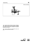
DOC023.52.00076.Jun05
EVITA® OXY
User Manual
© HACH LANGE GmbH, 2005. All rights reserved. Printed in Germany
Contents
Introduction.......................................................... 2
Mechanical installation ....................................... 4
Transmitter ............................................................ 4
Assembly ............................................................... 6
OXY 4100 .............................................................. 8
OXY 4150/3150 ..................................................... 9
USC 5000/6000/7000 .......................................... 10
USC 6000/7000 19” version ................................ 11
Optional add-on module USC 6000/7000 ........... 12
Optional add-on module USC 6000/7000
19” version ........................................................... 13
Programming USC 5000/6000/7000 ................. 20
Keypad and display layout .................................. 20
Factory settings ................................................... 21
Menu structure .................................................... 22
USC 7000 multidrop system ................................ 25
Setting of oxygen/temperature units and
transmitter’s current output .................................. 26
USC 5000/6000 current output settings .............. 27
USC 7000 current output settings ....................... 28
USC 6000 relay output settings ........................... 29
USC 7000 relay output settings ........................... 30
Troubleshooting ................................................ 40
Error system ....................................................... 40
Troubleshooting guide OXY 4100/3150/4150 stand alone transmitter .... 42
OXY 4100/3150/4150 transmitter ........................ 43
USC ..................................................................... 44
Technical Data ................................................... 48
Transmitter .......................................................... 48
USC ..................................................................... 50
HART® ................................................................. 52
Calibration .......................................................... 31
Electrical installation ........................................ 14
OXY 4100/4150/3150 stand alone transmitter .... 14
USC 5000/6000 and OXY 4100/4150
point to point ........................................................ 16
USC 7000 and OXY 4100/4150 multidrop........... 17
Initial start up ..................................................... 18
OXY 4100/4150/3150 stand alone transmitter .... 18
System with USC 5000/6000/7000 ..................... 19
Appendix I .......................................................... 53
Maintenance ...................................................... 33
Appendix IIa ....................................................... 54
Other Settings .................................................... 34
System information .............................................. 35
Forced current and relay outputs ........................ 38
Appendix IIb ....................................................... 55
Warranty, liability and complaints.................... 56
Contacts ............................................................. 57
1
2
Introduction
EVITA® OXY sensors are used for measuring
the concentration of dissolved oxygen in water
– especially in controlling and monitoring aeration
processes in wastewater treatment plants, but also
in applications such as fish frarms.
OXY 1100 sensor
EVITA® OXY consists of an OXY 1100 sensor, an
OXY 4100 transmitter and a USC Universal Signal
Converter.
USC 5000 IP 67 (NEMA 4X)
There are two versions of the transmitter – a ball
float version, OXY 4100, and a probe version, OXY
4150/3150. The operating principle is identical for
both versions.
OXY 4100 transmitter
There are three versions of the USC - a USC 5000
basic version, and a USC 6000 with added features,
both point to point. A USC 7000 with HART®
multidrop functionality enabling up to 15 transmitters
on only two wires.
USC 6000/7000 IP 67 (NEMA 4X)
The EVITA® OXY 1100 sensor is the heart of
the oxygen meter. The transmitter converts the
measurements by the sensor into a current signal
and at the same time also performs the necessary
calculations/corrections. The signal converter is the
display and programming unit and offers additional
outputs.
Documentation needs to be consulted.
OXY 4150/3150 transmitter
The user shall be made aware of that, if the
equipment is used in a manner not specified
by the manufacturer, the protection provided
by the equipment may be impaired.
USC 6000/7000 19”
The EVITA® OXY system offers several advantages:
2-wire transmitter
– simple and fast installation
Easy maintenance
–
simple automatic calibration in atmospheric
air initiated by using the TILTCAL® or the USC
5000/6000/7000
–
–
self-cleaning ball float
simple sensor replacement after 2-3 years
High reliability
–
–
–
self-diagnosing
membrane leakage detection
fault indication on transmitter current output
Flexible communication
–
HART® communication as standard gives added
features
setting of measuring range and units from a
distance
display of dissolved oxygen and temperature,
remaining OXY 1100 sensor life and specific
event codes
–
Option module can be fitted in the USC
6000/7000 without the need for tools
3
4
Mechanical installation
Transmitter
Mounting on a handrail
The mounting bracket for OXY 4100 and 4150 can
be mounted directly on a handrail using the supplied
hose clips. Retighten the hose clips after a few
days use to ensure a tight mounting of the mounting
bracket.
In case of strong sideways forces, the PVC pipe
should be mounted with supporting wires. This takes
up some of the sideways mechanical forces on the
pipe and avoids cracking of the mounting bracket.
(m
ax
.1
4 ’)
vmin.= 0.05 m/s (2”/sec).
Fig. 1
Fig. 2
Mounting on a concrete wall
Pipe mounting
The mounting bracket for OXY 4100 and 4150 can
be mounted directly on to a concrete wall using 2
screws AISI 316 (diameter max. 10 mm or 3/8 UN).
The OXY 4150 transmitter can be mounted in a PVC
pipe as shown in fig. 4.
Mounting of OXY 4150 transmitter
using cable bracket
The strength of the transmitter cable is such that the
transmitter can be allowed to hang from it.
Bracket (A) is available as accessory supplied by
HACH LANGE. However, (B) is not.
B
or 3/8 UN
A
Fig. 3
Fig. 4
Fig. 5
5
6
Assembly
Ball float assembly
Mount the single parts as shown in fig. 6.
E
Q
D
Q
C
Q
A: OXY 4100; 1 1/4” pipe thread
B: is supplied with transmitter
B
C: 45° PVC or ABS elbow; inside diameter: 50 mm
or 1 1/2”; supplied by customer
D: PVC or ABS tube; 50 mm or 1 1/2”; supplied by
customer
A
E: 90° PVC or ABS elbow; inside diameter: 50 mm
or 1 1/2”; supplied by customer
Q: PVC or ABS adhesive; supplied by customer
Fig. 6
Probe assembly
Mount the single parts as shown in fig. 6a.
F
Q
E
Q
D
Q
C
A: OXY 4150/3150; diameter 50 mm
B: adaptor with 11/4” pipe thread (085G3325) or
union with diameter 50 mm (081B0028); is
supplied with system packages 1A and 2A
B
C: adaptor with 1½” and 50 mm outside diameter
(081B0027); is supplied with system packages
1A and 2A
A
D: PVC or ABS socket; inside diameter: 50 mm or
1½”; supplied by customer
E: PVC or ABS tube; 50 mm or 1½”; supplied by
customer
Fig. 6a
F: 90° PVC or ABS elbow; inside diameter: 50 mm
or 1½”; supplied by customer
Q: PVC or ABS adhesive; supplied by customer
7
8
OXY 4100
Mounting and replacement of OXY
1100 sensor
Mount the sensor on the ball float as shown in fig. 7.
At mark 5: Turn until a “click” is heard.
Fig. 7
OXY 4150/3150
Mounting and replacement of OXY
1100 sensor
Mount the sensor on the probe as shown in fig. 8.
At mark 5: Turn until a “click” is heard.
Fig. 8
9
10
USC 5000/6000/7000
Mounting on a handrail
Mounting on a concrete wall
Mount the bracket on a vertical or horizontal pipe
using the two stainless steel hose clips.
Mount the bracket on to a wall using four screws
(diameter max. 8 mm or 5/16 UN).
Fig. 10
Fig. 9
Fig. 11
Fig. 12
USC 6000/7000 19” version
Mounting in panel
First mount the terminal board in the front panel IP
65 (NEMA 4X) enclosure, figs. 13 and 14, or the
back of the panel bracket, fig. 15. Plug in the 19”
USC 6000/7000 signal converter in the enclosure or
bracket using the four small screws to tigthen it.
Fig. 13
Fig. 14
Fig. 15
11
12
Optional add-on module USC 6000/7000
Unpack the add-on module and locate it in the bottom of the signal converter as shown in fig. 16.
Press the add-on module forward as far as possible.
See fig. 17. Avoid touching the pc board and the
sockets.
The add-on module has now been installed and
the signal converter is ready to be installed on the
terminal box. The menus related to the optional
add-on module will automatically become visible
and electrical inputs and outputs are automatically
established by power on.
Fig. 16
Fig. 17
Fig. 18
Optional add-on module USC 6000/7000 19” version
Unpack the add-on module and locate it in the
bottom of the signal converter as shown in fig. 19.
Press the add-on module forward as far as possible.
See fig. 20. Avoid touching the pc board and the
sockets.
The add-on module has now been installed and
the signal converter is ready to be installed on the
terminal box. The menus related to the optional
add-on module will automatically become visible
and electrical inputs and outputs are automatically
established by power on.
Fig. 19
Fig. 20
Fig. 21
13
14
Electrical installation
OXY 4100/4150/3150 stand alone transmitter
The transmitter is connected using the two-wire,
shielded cable. The two leads carry supply voltage,
a 4-20 mA current signal, and HART® communication.
+
If the cable is extended, the total length of the cable
must not exceed 1000 m (3000’). Always use twowire, shielded cable for the extension (min. 2 x 0.2
mm2 (24 AWG)).
–
Red
Shield
Examples of coupling to loop-powered display and
PLC/SCADA system are shown in fig. 22, fig. 23 and
fig. 24, respectively.
A suitable power supply shall be considered
in the end-use application. The power supply
must be a Class 2 power source (limited
circuit) according to the National Electrical
Code (NEC) and provided double/reinforced
insulation between mains and the 12-30 V
d.c. supply for the oxygen transmitter.
Black
EVITA® OXY connected to loop-powered display.
Fig. 22
Note: Components like motors, pumps and
computers may cause high voltage potential
differences between the protective earth/
ground wire and the water in the tank, that
results in unstable readings. If this problem
occurs, mount an earthing electrode in the
tank to equalise the electrical potential of the
water to PE.
If the flow velocity in the tank is high, it may
cause a static potential locally. Is this the
case, mount the earthing electrode close to
the transmitter.
Red
Black
Shield
Black
Red
Shield
EVITA® OXY supplied from PLC/SCADA
system.
Fig. 23
Fig. 24
EVITA® OXY connected to a PLC/SCADA
system with external power supply.
15
16
USC 5000/6000 and OXY 4100/4150 point to point
The transmitter is connected using the two-wire,
shielded cable. The two leads carry supply voltage,
a 4-20 mA current signal and HART® communication.
USC 5000/6000 - IP 67 version
If the cable is extended, the total length of the cable
must not exceed 1000 m (3000’). Always use twowire, shielded cable for the extension (min. 2 x 0.2
mm2 (24 AWG)).
On the USC signal converter it is possible to
disable the function of the digital input (used for
calibration control on the EVITA INSITU 4100
transmitter).
Depending on the USC version the power supply
should be connected to terminals L, N and PE when
using 100-240 V a.c., or to terminals 1 and 2 when
using 24 V a.c./d.c., see fig. 25 and fig. 26.
Note: The digital input is available on both USC
5000, USC 6000 and USC 7000.
USC 6000 - 19” version
Fig. 26
USC
Shield
Input
Relay 3
Black
Red
Relay 2
Relay 1
Shield
I out 1
Relay 3*
Black
USC
DIG IN
Digital input
Function
On
I out 2
Relay 2*
On
Off
Red
Relay 1*
081R9433.02.01
I out 1
I out 2*
Digital input
Digital input
Fig. 25
*Only USC 6000
Fig. 25a
USC 7000 and OXY 4100/4150 multidrop
The USC 7000 is able to communicate with up to
15 EVITA® OXY transmitters using HART® multidrop
protocol on only two wires.
Each transmitter should be connected in parallel
outside the USC connection box and only two wires
with shield mounted on the terminals in the USC
7000.
Note: Components like motors, pumps and
computers may cause high voltage potential
differences between the protective earth/
ground wire and the water in the tank, that
results in unstable readings. If this problem
occurs, mount an earthing electrode in the
tank to equalise the electrical potential of the
water to PE.
If the flow velocity in the tank is high, it may
cause a static potential locally. Is this the
case, mount the earthing electrode close to
the transmitter.
Relay 5
Important: The below mentioned warnings concern
both USC 5000, USC 6000 and USC 7000.
The HART communication terminals (84/85)
and the Digital Input terminals (77/78) of
the Universal Signal Converter must not be
connected to external voltage level above 30
V d.c.
The Relay terminals (40-49) of the Universal
Signal Converter must not be connected to
external voltage level exceeding 48 V d.c., 30
V rms or 42 V peak.
Protective conductor terminal. Required cable
min. AWG16 or 1.5 mm2 Cu.
Relay 4
Shield
Relay 3
Relay 2
Black
Red
Relay 1
I out 1
I out 2
I out 3
I out 4
Digital input
Fig. 27
Field wiring installation of the Universal Signal
Converter must be in accordance with the
National Electrical Code.
Mains supply 100 to 240 V a.c. from building
installation (Overvoltage category II). A switch
or circuit-breaker (max. 15 A) shall be included
in the building installation. The switch/circuitbreaker shall comply with relevant requirements of IEC 947-1 and 947-3. It must be in
close proximity to the equipment and within
easy reach of the operator, and it shall be
marked as the disconnecting device for the
equipment.
17
18
Initial start up
OXY 4100/4150/3150 stand alone transmitter
1. Apply voltage with the OXY 1100 sensor pointing
upwards in free air for 2 minutes. This will zero
the sensor life counter. The life counter can be
read via the signal converter (USC) or HART®
communication.
Fig. 28
2. Place the transmitter so that the OXY 1100
sensor points downwards, still in free air. Leave
it in this position for 1 hour to allow the sensor to
stabilise.
Fig. 29
3. Calibrate in accordance with the instructions in
the “Calibration” section p. 31.
System with USC 5000/6000/7000
1. Place the transmitter in free air so that the OXY
1100 sensor points downwards, see fig. 30.
2. Turn on the power to the signal converter USC
5000/6000/7000.
4. Check factory settings, see p. 21. Change if
necessary.
3. Leave the transmitter in this position for at least
1 hour to allow the sensor to stabilise before
calibrating.
5. Reset the lifetime counter, see fig. 32, p. 22.
6. Calibrate in accordance with the instructions in
the “Calibration” section, p. 31.
7. After calibration is completed, place the
transmitter in the measuring media.
Fig. 30
19
20
Programming USC 5000/6000/7000
Keypad and display layout
Fig. 31
TOP UP KEY
(ESC)
This key (hold for 2 sec.) is used to switch between the
operator menu and setup menu. A short press will cause
a return to the overlying menu.
FORWARD KEY
This key is used to step forward through the menus in the
setup menu.
BACKWARD KEY
This key is used to step backward through the menus.
CHANGE KEY
This key changes the settings or numerical values in
the setup menu. In the operator menu it is used to step
through the menues.
SELECT KEY
This key selects which digits to be changed.
LOCK/UNLOCK KEY
(ENTER)
This key allows the operator to change settings and gives
access to submenus.
Various display symbols
Ready for change
Value locked
Access to submenu
Confirmation of choice
The keypad is used to set the EVITA® OXY and to
step through the menus. The function of the keys
are as follows:
IMPORTANT:
The USC starts up showing the menu “Language”
in English. Press the
key until the wanted
language appears in the display and press the
key.
After the language is chosen, the USC will show
“Concentration” in the operator menu (see p. 22).
The factory setting of the language can be
reestablished as follows:
•
Switch off the power supply
•
Press the
supply
•
Release the
key and switch on the power
key after 10 seconds
The language is now reset to English.
Factory settings
The EVITA® OXY system is supplied with the
following factory settings:
Parameter
Factory settings
Options
Current output 1
(System packages 1 and 2)
0-20 mg/l
Range:
USC 5000/6000/7000
Span:
Current output 2
(System package 1)
Range:
Span:
min. -10°C
max. 70°C
min. 1°C
Current outputs
USC 5000/6000/7000
OFF
OFF
ON
Relays 1, 2 and 3 (USC 6000)
OFF
Alarm; Warning; Limit; Timer; OFF
Relays 1, 2, 3, 4 and 5 (USC 7000)
OFF
Alarm; Warning; Limit; Timer; OFF
Enabled
Enabled; Disabled
Password
1000
1000-9999
Oxygen unit
mg/l
mg/l; ppm; %
Temperature unit
°C
°C; °F
Current output when not measuring
Low
High; Low; Hold
Current output during error
Low
High; Low; Normal
Time constant
40 sec.
10-300 sec.
TILTCAL
OXY 4100/4150
0-40 °C
min. 0 mg/l or ppm; 0%
max. 50 mg/l or ppm; 500%
min. 1 mg/l or ppm; 10%
®
If factory settings are satisfactory, proceed to p. 31.
21
22
Menu structure
Fig. 32
12.31 mg/l
Oxygen
Transmitter 0
7.09 mg/l
Oxygen
Transmitter 1
2.51 mg/l
Oxygen
Transmitter 2
6.22 mg/l
Oxygen
Transmitter 15
Error pending
Scan HART bus
Operator menu
The operator menu is for daily use. After the
language has been selected, the signal converter
starts up in the operator menu showing the actual
concentration of dissolved oxygen.
18.5°C
Temperature
Transmitter 0
0
Calibration
Transmitter 0
No. of alarms
Transmitter 0
Calibration
Transmitter 1
No. of alarms
Transmitter 1
Calibration
Transmitter 2
No. of alarms
Transmitter 2
Calibration
Transmitter 15
No. of alarms
Transmitter 15
0
18.5°C
Temperature
Transmitter 1
18.5°C
Temperature
Transmitter 2
0
18.5°C
Temperature
Transmitter 15
0
The USC 5000/6000 is point-to-point installation
while the USC 7000 is for a multidrop system. In fig.
32 menus marked with grey are only visible in the
multidrop system. It is possible to hide some of the
menus in the operator menu, see fig. 43, p. 34.
50.%
Rem. Lifetime
Transmitter 0
72. d
Reset lifetime
Transmitter 0
Last calibration
Transmitter 0
Reset lifetime
Transmitter 1
Last calibration
Transmitter 1
Reset lifetimes
Transmitter 2
Last calibration
Transmitter 2
Reset lifetime
Transmitter 15
Last calibration
Transmitter 15
85.%
Rem. Lifetime
Transmitter 1
26. d
70.%
Rem. Lifetime
Transmitter 2
84. d
95.%
Rem. Lifetime
Transmitter 15
71. d
081R9301.02.01
The menu of the signal converter is built up in two
parts. An operator menu and a setup menu.
Setup menu
The setup menu is shown in an overview diagram
(fig. 33) on page 24.
• View mode is a read only mode. The preselected
settings can only be scanned. The view mode is
accessed by pressing the
key for 2 seconds.
Instead of keying in the password, press the
key.
The factory setting of the password can be reestablished as follows:
• Switch off the power supply
• Press the
The setup menu consists of two parts:
• USC setup menu - for USC settings
• Transmitter setup menu - for transmitter settings
The setup menu is for commissioning and service
and for changing the settings. Access to the setup
menu is gained by pressing the
key for 2
seconds. The setup menu will operate in two modes:
• Setup mode is a read and write mode. The preselected settings can be scanned and changed. The
setup menu is accessed by pressing the
key for
2 seconds and entering the password. The factory
set password is 1000, but can be changed to any
value between 1000 and 9999.
• Release the
key and switch on the power supply
key after 10 seconds
The password is now reset to 1000.
23
24
Fig. 33
USC
USC
USC
Output
Input
Reset
mode
USC
USC
USC
Service
mode
Product
identity
HART Settings
~
USC
Settings
10.64 mg/l
~
Password
0000.
USC
USC
USC
Operator menu
setup
Password
Language
Temperature
Transmitter 0
42. d
Calibration
Transmitter 0
USC
USC
USC
USC
USC
USC
USC
I out 1-4
Digital input
Set default
setting
I Out 1-4
Type
USC5000
Change HART
Trm. Mode
OXY
12. d
No. of alarms
Transmitter 0
Relay 1-5
72. h
Relay 1-5
Rem. lifetime
Transmitter 0
Digital input
Event log
Reset lifetime
Transmitter 0
HART comm. error
10.64 mg/l
Oxygen
Transmitter 0
42. d
Calibration
Transmitter 0
TR. 0
TR. 0
TR. 0
TR. 0
TR. 0
Settings OXY
Ser.No. SSSSVVNUUÅ
Basic settings
Advanced settings
Send command
Info
12. d
No. of alarms
Transmitter 0
72. h
Rem. lifetime
Transmitter 0
Reset lifetime
Transmitter 0
Last calibration
Transmitter 0
TR. 0
TR. 0
TR. 0
TR. 0
Oxygen unit
ppm
Set transmitter
address 00
Calibration
Time since last
calibr.
Value at 4 mA
Value at 20 mA
Temp. unit
Error pending
Serial no.
SW version
HW version
Further info.
Last calibration
Transmitter 0
Temperature
Transmitter 0
Code no.
Calibr. type
After calibration
TILTCAL
Start measuring
Reset lifetime
Set factory settings
Error pending
Event log
TILTCAL
Sensor type
Transmitter mode
Salinity
Manufacturer Id.
Rel. humidity
Output when not
measuring
Output during error
Time constant
Mfr. device type
Univ. cmd. rev.
Transm. cmd. rev.
SW version
Scan HART bus
HW version
Device id.
Scan HART bus
081R9418.02.02
Oxygen
Transmitter 0
USC 7000 multidrop system
Changing transmitter address from default
To allow the USC 7000 to recognise the transmitter
on the HART® bus, the transmitter needs a unique
address between 1 and 15. The EVITA® OXY
transmitter is factory delivered with the address 0,
which is used for point-to-point installations (USC
5000/6000).
To programme the address of a new transmitter,
connect the transmitter to the USC 7000 and press
“Scan HART bus”. The transmitter will get the next
available address between 1 and 15.
Note: If, before scanning the HART® bus, a transmitter with address higher than 0 was registered as
interrupted, the new transmitter will be assigned this
address.
081R9302.02.02
Password
0000.
USC
Settings
10.64 mg/l
Oxygen
Transmitter 0
Temperature
Transmitter 0
42. d
Calibration
Transmitter 0
12. d
No. of alarms
Transmitter 0
72. h
TR. 0
TR. 0
TR. 0
Settings OXY
Ser.No. SSSSVVNUUÅ
Basic settings
Advanced settings
Rem. lifetime
Transmitter 0
Reset lifetime
Transmitter 0
TR. 0
Set transmitter
address 00
Last calibration
Transmitter 0
Error pending
Scan HART bus
USC
USC
USC
Scan HART bus
Are you sure ?
Scan HART bus
Busy
Trm. address 0
changed to 05
Fig. 34
25
26
Setting of oxygen/temperature units and transmitter’s current output
If other settings are wanted, the factory settings can
be changed as shown below.
Fig. 35
Setting of the displays and current outputs units
for oxygen and temperature can be done in “Basic
settings”. Setting of the transmitter’s measuring
range for oxygen can be done by changing the value
at 4 mA and the value at 20 mA.
However the setting of current outputs range for
oxygen and temperature is done as shown in fig. 36,
p. 27 and fig. 37, p. 28.
USC 5000/6000 current output settings
Setting of current output 1 on USC 5000 and current
outputs 1 and 2 on USC 6000.
Fig. 36
USC
Output
**
USC
USC
I out 1
I out 2
* Units selected in “Transmitter basic settings“, see fig. 35, p. 26.
** Only USC 6000
Same as I out 1
I OUT 1
Function
Off
On
Off
I OUT 1
I OUT 1
Value
pH
Value at 4 mA
+000.00 mg/l
Value at 20 mA
+999.00 mg/l
Range: 0-999
Range: 0-999
pH
Temperature
I OUT 1
081R9412.02.01
Value at 4 mA
+000.00 °C
Range: -10 - 999
*
*
I OUT 1
I OUT 1
*
*
I OUT 1
I OUT 1
I OUT 1
Output when not
measuring 20 mA
Output during
error Normal
Time const.
040. s
20 mA
4 mA
Hold
Normal
23 mA
3.8 mA
Normal
030-300s
Value at 20 mA
+999.00 °C
Range: -10 - 999
27
28
USC 7000 current output settings
Setting of current outputs 1 to 4 on USC 7000.
USC
Output
USC
USC
USC
USC
I out 1
I out 2
I out 3
I out 4
Same as I out 1
Same as I out 1
* Units selected in “Transmitter basic settings”, see fig. 35, p. 26.
Same as I out 1
I OUT 1
Function
Off
On
Off
*
I OUT 1
I OUT 1
I OUT 1
Select
transmitter 00
Value
Oxygen
Value at 4 mA
+00.00 mg/l
Value at 20 mA
+999.00 mg/l
Range: 0-999
Range: 0-999
00-15
I OUT 1
*
Oxygen
Temperature
081R9413.02.01
Fig. 37
I OUT 1
Value at 4 mA
+000.00 °C
Range: -10 - 999
*
I OUT 1
Value at 20 mA
+999.00 °C
Range: -10 - 999
*
I OUT 1
I OUT 1
I OUT 1
Output when not
measuring 20 mA
Output during
error Normal
Time const.
040. s
20 mA
4 mA
Hold
Normal
23 mA
3.8 mA
Normal
030-300s
USC 6000 relay output settings
*
**
Setting of relay outputs 1 to 3 on USC 6000.
081R9414.02.02
USC
USC
~
Output
I out 1
Units selected in “Transmitter basic settings” fig. 35, p. 26
To allow the current output to stabilise after a cleaning, the
USC locks the current output during “Cleaning time” and
additional 10 minutes.
USC
USC
USC
Relay 1
Relay 2
Relay 3
Same as Relay 1
Same as Relay 1
RELAY 1
Relay at
error Open
RELAY 1
Function
Off
On
Timer
Off
Open/Closed
RELAY 1
RELAY 1
Function
Error
Error
Warning
Hi Limit
Lo Limit
Cleaning
Relay at
warning Open
Open/Closed
RELAY 1
*
RELAY 1
RELAY 1
RELAY 1
Value
Oxygen
Setpoint
050.00 mg/l
Hysteresis
005.00 mg/l
Relay above
limit Open
Oxygen
Temperature
0 - 999.99
0 - 999.99
Open/Closed
RELAY 1
*
*
RELAY 1
Setpoint
035.00 ºC
Hysteresis
005.00 ºC
0 - 999.99
0 - 999.99
*
RELAY 1
Same as Hi Limit
Relay below
limit Open
Open/Closed
Fig. 38
**
RELAY 1
RELAY 1
RELAY 1
Cleaning interval
000. h
Cleaning time
00 min
Relay at
cleaning Open
1-999 h
1-59 min
Open/Closed
RELAY 1
RELAY 1
RELAY 1
Timer interval
000. h
Active time
00 min
Relay at
active Open
1-999 hours
1-59 min
Open/Closed
29
30
USC 7000 relay output settings
*
**
Setting of relay outputs 1 to 5 on USC 7000
Units selected in “Transmitter basic setting”, fig. 35, p. 26.
To allow the current output to stabilise after a cleaning, the
USC locks the current output during “Cleaning time” and
additional 10 minutes.
USC
USC
USC
USC
USC
USC
Relay 1
Relay 2
Relay 3
Relay 4
Relay 5
Same as Relay 1
Same as Relay 1
Same as Relay 1
081R9415.02.02
USC
I out 1
~
Output
RELAY 1
Same as Relay 1
Relay at
error Open
Open/Closed
RELAY 1
Relay at
warning Open
Open/Closed
RELAY 1
Function
Off
One transmitter
All Errors
All Warnings
Timer
Off
RELAY 1
RELAY 1
Select
transmitter no. 00
00-15
Function
Error
Error
Warning
Hi Limit
Lo Limit
Cleaning
RELAY 1
RELAY 1
Value
Oxygen
Setpoint
050.00 mg/l
0 - 999.99
Oxygen
Temperature
RELAY 1
*
RELAY 1
*
*
Setpoint
035.00 ºC
0 - 999.99
RELAY 1
RELAY 1
Relay above
limit Open
Open/Closed
Hysteresis
005.00 mg/l
0 - 999.99
*
Hysteresis
005.00 ºC
0 - 999.99
RELAY 1
Same as Hi Limit
Relay below
limit Open
Open/Closed
**
RELAY 1
RELAY 1
RELAY 1
Cleaning interval
000. h
Cleaning time
00 min
Relay at
cleaning Open
1-999 h
1-59 min
Open/Closed
RELAY 1
Relay at
Error Open
Open/Closed
RELAY 1
Relay at
warning Open
Open/Closed
Fig. 39
RELAY 1
RELAY 1
RELAY 1
Timer interval
000. h
1-999 hours
Active time
00 min
1-59 min
Relay at
active Open
Open/Closed
Calibration
EVITA® OXY sensors must be calibrated in
atmospheric air. Calibration every 6 months is
recommended. Calibration can be initiated from the
USC 5000/6000/7000 or by using the TILTCAL®
feature in the OXY transmitter. During calibration,
the OXY 1100 sensor must not be exposed to direct
sunlight.
Before calibration, the OXY 1100 sensor must
be cleaned, see section “Maintenance”. With fast
calibration in atmospheric air a 1% system accuracy
can be obtained. Temperature and barometric
pressure compensation is made automatically
during calibration via an internal temperature and
pressure sensor.
Using TILTCAL®
Hold the transmitter with the OXY 1100 sensor
upwards to initiate calibration by activating the tilt
switch. After 5 min. turn the transmitter with the OXY
1100 sensor downwards and the transmitter has
completed the calibration routine. During calibration,
the current output signal is factory set to 4 mA.
Optional 20 mA or the last measured value (Hold)
can be chosen via the USC 5000/6000/7000.
TILTCAL®
Fig. 40
Tilted
Not tilted
31
32
If during the 5 minutes calibration period the
transmitter is turned with the OXY 1100 sensor
downwards, calibration stops and measurements
continue with the previous calibration value.
Temperature compensation is made automatically
during calibration via an internal temperature sensor.
In addition, using factory settings, compensation
is also made for air pressure, relative humidity
and salinity. These factory-set values can be
changed via the USC signal converter or via HART®
communication.
Using the USC 5000/6000/7000
In operator menu use the
key to select the
“Calibration” menu and press the
key to initiate a
calibration.
Compensations for relative humidity and salinity can
be made by entering these values using the USC
5000/6000/7000, see fig. 48, p. 37.
The set values and the significance of deviations
from them are given in appendix I.
A system accuracy of 0.5 % can be achieved by
lifting the transmitter out of the medium and placing
it with the OXY 1100 sensor downwards for 1 hour
to make sure the sensor is completely stabilised.
Calibration can then be initiated.
* See “Advanced settings, fig. 48, p. 37.
USC 5000/6000/7000
calibration
Fig. 41
Maintenance
Under normal conditions, the OXY 1100 sensor will
operate for 2-3 years and can be replaced in a few
minutes.
General maintenance of the EVITA® OXY sensor
is limited to cleaning about every 2-3 months and
calibration about every 6 months.
Cleaning (OXY transmitter)
During cleaning, the sensor must not be allowed to
remain pointing upwards for more than 3 minutes at
a time if the TILTCAL® function is enabled, otherwise
a calibration cycle will start. The TILTCAL® function
can be disabled according to fig. 48, p. 37.
1. Lift the transmitter out of the medium.
2. Clean the sensor with pure water, to which a little
cleaning agent/washing-up liquid can be added.
3. Dry the sensor with a soft cloth.
4. Immerse the transmitter into the medium to be
measured.
Cleaning (USC signal converter)
When considered necessary, clean the USC signal
converter using a soft moist cloth.
Replacement of sensor
1. Remove the defective/worn sensor.
2. Insert new sensor (see fig. 7, p.8 or fig. 8, p. 9).
3. Reset the lifetime counter (see p. 18 or fig. 32, p.
22).
4. Place the transmitter so that the OXY 1100
sensor points downwards. Keep it in this position
for at least 1 hour to allow the new sensor to
stabilise (see fig. 29, p. 18).
5. Perform calibration (see section “Calibration” p.
31-32).
Fig. 42
33
34
Other Settings
In the “Operator menu setup” it is possible to hide all
menus except “Oxygen” in the operator menu.
• A
in the operator menu setup
means that this reading is shown in
the operator menu.
Fig. 43
• A
in the operator menu setup
means that this reading is not
available when viewing the operator
menu.
System information
Transmitter information
In the menu “Info” it is possible to view various
information about the transmitter, e.g. time since
last calibration, transmitter mode and software and
hardware versions.
Fig. 44
USC information
In the menu “Product identity” it is possibel to read
the USC type (5000/6000/7000) and the serial
number.
Fig. 45
35
36
Reset mode
The factory settings can be re-established as shown
in fig. 46.
Fig. 46
Send command
In the “Send command” menu it is possible to start
calibration, to start measuring after calibration, to
reset lifetime and to set factory settings.
See fig. 41, p. 32
Fig. 47
Advanced settings
In the “Advanced settings” menu it is possible to
choose which calibration type to be used and which
type of start after calibration. Furthermore factors for
compensation for salinity and relative humidity can
be keyed in.
“Automatic calibration” means calibration in
atmospheric air and “Manual calibration” means
calibration in a standard solution where the
concentration of oxygen is keyed in, see fig. 41, p.
32.
“Transmitter address” has to be 0 for current output
to function in a point-to-point installation using USC
5000 or 6000. When operating in multidrop system
using USC 7000, the transmitter must have a
unique address between 1 and 15.
TR. 0
TR. 0
TR. 0
TR. 0
TR. 0
TR. 0
TR. 0
Advanced settings
Set transmitter
address 00
Calibr. type
Manual
After calibration
Automatic start
TILTCAL
Enabled
Mem leakage detect
Enabled
Sensor type
50 um
00-15
Manual
Automatic
Manual start
Automatic start
Enabled
Disabled
Enabled
Disabled
25
50
125 um
TR. 0
TR. 0
TR. 0
TR. 0
TR. 0
Salinity
040. g/l
Rel. humidity
060. %
Output when not
measuring Low
Output during
error Low
Time const.
040. s
0-40 g/l
0-100 %
High
Low
Hold
High
Low
Normal
10-300 s
Fig. 48
37
38
USC
USC
USC
USC
USC
Service
mode
I Out 1
I Out 2
I Out 3
I Out 4
081R9406.02.02
Forced current and relay outputs
I OUT 1
Service mode
Mode
Normal
In the “service mode” it is possible to control the
relay and the current outputs directly. This may be
useful when e.g. a control loop is to be adjusted or if
an alarm signal should be checked.
Normal
Forced
The quality of the HART® communication is
displayed in the “HART comm. error” submenu.
The quality is shown as:
VVVV XXXX YYY % ZZ
I OUT 1
Forced value
00.0 mA
00.0-24.0 mA
USC
USC
USC
USC
USC
Relay 1
Relay 2
Relay 3
Relay 4
Relay 5
RELAY 1
Mode
Normal
where
VVVV
is the number of received messages
without any errors,
XXXX is the number of received messages
with errors,
YYY % is the percentage of messages that
had errors
ZZ
is the number of messages that were
eliminated, i.e. max. number of retries
was reached.
Fig. 49
Normal
Open
Closed
USC
USC
USC
Digital input
High
Event log
HART comm. error
0856 0007 001% 00
(High/Low)
USC
Log xxxxdxxh
xxxxxxxxxxxxxxxx
39
40
Troubleshooting
Error system
The EVITA® OXY has an advanced self-diagnostic
system. If there is an error or a warning, a flashing
bell
is displayed. To view the pending error
information, press the
key in the operator menu
– see below.
Operator menu
Fig. 50
The USC and the transmitter each has an ‘event log’
that stores past errors, information and warnings.
To access the USC event log, see fig. 49, p. 38. To
see the transmitter event log, see fig. 44, p. 35.
Each event has an unambiguous identification
consisting of 4 digits:
E
O
5
5
EO55: The OXY 1100 diaphragm has
been damaged.
1. digit:
Category
I(Information);
W(Warning);
E(Error)
2. digit:
Sensor type
U for USC
O for OXY
I for INSITU 4100
N for INSITU 5100
P for PH/REDOX
S for TSS
3. and 4. digit:
Error number 00-99
The numbers are
describing the
following events:
0-9
Information
10-49 Warning
50-99 Error
Information
The system will continue to measure as usual. Relay
and output signals will not be affected.
Warning
The system will continue to measure, but there has
been an event, which may cause malfunction of the
system, and which may require an operator. The
reason for the warning may disappear on its own.
Warning relay, if defined, will show warning in
accordance with the setup.
Error
The whole system or parts of it is malfunctioning,
and the output signal is not reliable anymore. The
errors require an operator.
Error relays, if defined, will show error in accordance
with the setup.
The EVITA® OXY transmitter error pending list
shows the 5 latest occured errors that are still
pending, and the event log shows the 25 latest
events, i.e. informations, warnings and errors.
The USC signal converter error pending list can
show up to 14 pending errors and warnings,
displayed with the USC errors first and then the
transmitter errors. If there are more than 14 pending
errors, the message “Additional errors cannot be
viewed” will show in the display. The USC event log
shows the 9 latest events.
41
42
Troubleshooting guide - OXY 4100/3150/4150 stand alone transmitter
Symptom
Current signal
Fault
Remedy
Constant current signal
(varying oxygen concentration)
I = 0 mA
Incorrect wiring
Check wiring and make the necessary corrections.
Undervoltage
Check the supply voltage at transmitter.
Supply voltage must be at least 12 V.
Initialisation fault
1. Switch off transmitter for min. 5 seconds.
2. Switch on again while sensor points downwards.
Transmitter defective
Replace transmitter
Initialisation fault
1. Switch off transmitter for min. 5 seconds.
2. Switch on again while sensor points downwards.
Transmitter defective
Replace transmitter
I = 3.85 mA or
23.5 mA
Membrane leakage
Replace OXY 1100 sensor.
Moisture behind OXY 1100 sensor
Fully dry the terminals at transmitter.
A hair dryer might be of assistance.
I = 3.90 mA or
23.0 mA
Calibration not possible, worn OXY 1100 sensor
Replace OXY 1100 sensor.
I = 3.95 mA
Oxygen under set measuring range
Set the lower measuring limit to a lower value.
I = 22.00 mA
Oxygen level higher than set measuring range
Set the upper measuring limit to a higher value.
Variable
Calibration value incorrect
1. Check FSO in atmospheric air. Hold the transmitter up in
the air with the sensor downwards. Check value against
DS/EN 25814 (see appendix IIa)
2. Check zero point (see appendix IIb)
3. In the case of large reading error, recalibrate.
I = 3.80 mA or
24.0 mA
Error in measuring value
OXY 4100/3150/4150 transmitter
Symptom
Current output
signal
Error in measuring
value
Variable
Event
code
Cause
Remedy
Calibration value incorrect
1. Check FSO in atmospheric air. Hold the transmitter up
in the air with the sensor downwards. Check the value
against DS/EN 25814 (see appendix IIa)
2. Check zero point (see appendix IIb)
3. In the case of large reading error, recalibrate
End of calibration phase
Go to “Send command” menu and start measuring, see fig.
47, p. 36
WO10
The measured value has exceeded the transmitter output setting
Change upper range in “Basic settings”, see fig. 35, p. 26
WO11
The measured value is below the transmitter output setting
Change lower range in “Basic settings”, see fig. 35, p. 26
WO15
Life time expired. OXY 1100 should be replaced as soon as
possible
Replace OXY 1100
WO20
The temperature of OXY 1100 is below 0°C (32°F).
The accuracy might be reduced.
Accuracy reduced
WO21
The temperature of OXY 1100 is above 40°C (104°F).
The accuracy might be reduced.
Accuracy reduced
EO50
Calibration not possible.
OXY 1100 is worn or defective
Replace OXY 1100
EO51
Output signal from OXY 1100 is too low.
OXY 1100 is worn or defective
Replace OXY 1100
EO55
The OXY 1100 membrane has been damaged
Replace OXY 1100
EO60
Error in EEPROM
Replace transmitter
EO61
Error in communication between the µ-controller and the A/D
converter or error in the A/D converter
Replace transmitter
EO62
Error in the input circuit
Replace transmitter
EO63
Error in the temperature circuit
Replace transmitter
Display switching
between “Oxygen” and
“End of calibration”
Flashing bell in display
Depending on
the settings
43
44
USC
Symptom
Current output
Event code
Cause
Remedy
None
Undefined
IU00
Power on
Registration of time of power on
IU01
Add-on module applied
Registration of applied add-on module
IU02
Add-on module defective or removed
Replace or install add-on module
IU03
Parameter successfully corrected
Information
1. Supply voltage
2. USC 5000/6000/7000 defective
1. Check supply voltage
2. Replace USC 5000/6000/7000
Same as EU61 p. 45
Empty display
Dots in upper line of display
Flashing bell in display
(I out 1)
EU61
See EU61 p. 45
(I out 2)
EU62
See EU62 p. 45
(I out 3)
EU63
See EU63 p. 45
(I out 4)
EU64
See EU64 p. 45
Undefined
WU10
I out 1: Value at 4 mA >= Value at 20 mA
Check I out 1 setup
WU11
I out 2: Value at 4 mA >= Value at 20 mA
Check I out 2 setup
WU12
I out 3: Value at 4 mA >= Value at 20 mA
Check I out 3 setup
WU13
I out 4: Value at 4 mA >= Value at 20 mA
Check I out 4 setup
WU14
The measured value has exceeded the current output 1 setting
Change value at 20 mA on I out 1
WU15
The measured value has exceeded the current output 2 setting
Change value at 20 mA on I out 2
WU16
The measured value has exceeded the current output 3 setting
Change value at 20 mA on I out 3
WU17
The measured value has exceeded the current output 4 setting
Change value at 20 mA on I out 4
WU18
The measured value is below the current output 1 setting
Change value at 4 mA on I out 1
WU19
The measured value is below the current output 2 setting
Change value at 4 mA on I out 2
WU20
The measured value is below the current output 3 setting
Change value at 4 mA on I out 3
WU21
The measured value is below the current output 4 setting
Change value at 4 mA on I out 4
Symptom
Current output
Event code
Cause
Remedy
Flashing bell in display
Undefined
WU39
HART communication error
Check cables
WU40
TMS communication error
Replace TMS
WU41
A parameter is out of range.
It could not be replaced by its default value
Fixed at power-up
WU43
Too many errors at the same time.
Some errors are not registered correctly
Power-up USC
WU49
Internal error
Power-up USC
One or more
current outputs
= 3.8 mA or 24 mA
EU60
CAN bus application does not respond.
This error is shown when the maximum number of
communication attempts is exceeded.
1. Power-up USC
2. Replace USC
Undefined
EU61
USC unable to read data required for I OUT 1
1. No reply from transmitter
2. Transmitter has got new address
3. Another master conflicts on HART® comm.
4. Supply voltage for transmitter too low
5. Too much noise on current loop
6. Transmitter defective
7. USC defective
1. Check shielding and cable connections
2. Power-up USC
3. Disconnect the other master or set USC to
another master, see fig. 51, p. 52
4. Check supply voltage at transmitter,
supply voltage must be at least 20 V
5. Check shielding and cable connections
6. Replace transmitter
7. Replace USC
EU62
USC unable to read data required for I OUT 2
1 - 7: Same as EU61
Same as EU61
EU63
USC unable to read data required for I OUT 3
1 - 7: Same as EU61
Same as EU61
EU64
USC unable to read data required for I OUT 4
1 - 7: Same as EU61
Same as EU61
45
46
Symptom
Current output
Event code
Cause
Remedy
Flashing bell in display
Undefined
EU65
USC unable to read data required for relay 1
1 - 7: Same as EU61
Same as EU61
EU66
USC unable to read data required for relay 2
1 - 7: Same as EU61
Same as EU61
EU67
USC unable to read data required for relay 3
1 - 7: Same as EU61
Same as EU61
EU68
USC unable to read data required for relay 4
1 - 7: Same as EU61
Same as EU61
EU69
USC unable to read data required for relay 5
1 - 7: Same as EU61
Same as EU61
47
48
Technical Data
Transmitter
Measurement
Clark’s principle
Transmitter cable
Two-wire, screened cable 2 x 0.75 mm2 (18 AWG) cable, length 10 m (33’)
Supply voltage
Min. 12 Vd.c. - max. 30 Vd.c.
HART®: max. ripple (47 Hz - 125 Hz): 0.2 V p-p
max. noise (500 Hz - 10 kHz): 1.2 mV rms
Power consumption
Max. 720 mVA
Current output
3.80-24 mA
Time constant
10-300 s (default 40 s)
Digital communication
HART® communication superposed on current output
Alarm signal
On current output (see section “Trouble shooting”)
Measuring range (can be
configured)
Transmitter:
OXY 3150:
OXY 4100/4150:
Min. span:
4 - 50 ppm or mg/l; 40 - 500 %
0 - 50 ppm or mg/l; 0 - 500 %
1 ppm or mg/l; 10 %
Sensor (recommended values to maintain operating life):
OXY 1100, 25 µm:
0.002 - 2 ppm
OXY 1100, 50 µm:
0.1 - 10 ppm
OXY 1100, 125 µm: 2 - 50 ppm
Temperature range
Transmitter:
Operation:
Storage/transport:
-40°C - +60°C (-40°F to 140°F)
-40°C - +70°C (-40°F to 158°F)
Sensor:
Operation:
Storage/transport:
0°C - +50°C (32°F to 122°F)
0°C - +70°C (32°F to 158°F)
Measured media:
0°C - +40°C (32°F to 104°F)
System accuracy
Digital output:
±0.1 % of FSO at calibrating temperature
Analogue output:
±0.2 % of FSO at calibrating temperature
Digital/analogue output: ±0.5 % of FSO at 0 - 40°C (32°F to 104°F)
Reaction time OXY 1100
25 µm:
50 µm:
125 µm:
Diaphragm leakage monitoring
Measurement between anode and a terminal in contact with the measured medium
Enclosure
OXY 4100:
OXY 3150/4150:
IEC 529: IP 68 (1 m); NEMA 6P (3’)
IEC 529: IP 68 (10 m); NEMA 6P (30’)
Dimensions and weight
OXY 4100:
OXY 3150/4150:
d = 240 mm (9.6”);
d = 50 mm; l = 180 mm (d = 2.0”; l = 7.2”);
Materials
PBT/PC
EMC
Emission:
Immunity:
τ =
τ =
τ =
7s
22 s
110 s
2.7 kg (6 lb)
1 kg (2.2 lb)
IEC/EN 61000-6-3
IEC/EN 61000-6-2
The worn OXY 1100 sensor must be disposed as ordinary industrial waste, and the worn OXY 4100/4150 transmitter must be
disposed as electronic waste. Before disposing the OXY 4100/4150, the cable must be cut off and disposed as metallic waste.
Disposal in accordance with EU directive 2002/96/EC
In compliance with EU directive 2002/96/EC, HACH LANGE / the local subsidiary will accept back and dispose
of the old instrument at no cost.
ATTENTION!
It is not allowed to dispose of the instrument using municipal waste
disposal services. Please talk to your local HACH LANGE contact.
Important: Before returning goods to HACH LANGE, the products must be cleaned properly.
49
50
USC
Type
USC 5000
USC 6000
No. of transmitters
1 (point-to-point installation)
1 (point-to-point installation)
15 (multidrop)
Measuring
range
Dissolved oxygen:
Dissolved oxygen:
Temperature:
0 to 10 – 500 %
0 to 0.1 – 50mg/l or ppm
0 – 70°C (32°F – 158°F)
Dissolved oxygen:
Temperature:
0 to 10 – 500 %
0 to 0.1 – 50mg/l or ppm
0 – 70°C (32°F – 158°F)
Temperature:
0 to 10 – 500 %
0 to 0.1 – 50mg/l or ppm
0 – 70°C (32°F – 158°F)
Measuring
uncertainty
Oxygen:
Temperature:
± 0.5 %
± 0.5°C (0.9°F)
Oxygen:
Temperature:
± 0.5 %
± 0.5°C (0.9°F)
Oxygen:
Temperature:
± 0.5 %
± 0.5°C (0.9°F)
Current outputs
One 4-20 mA (scaleable),
24V active galvanic isolated
Max. load: 800 ohm
Two 4-20 mA (scaleable),
24V active galvanic isolated
Max. load: 800 ohm
Four 4-20 mA (scaleable), isolated
24V active galvanic
Max. load: 800 ohm
Relay outputs
None
3 relay outputs SPST (max. 48 Va.c. or 30 Vrms 4 A)
5 relay outputs SPST (max. 48 Va.c. or 30 Vrms 4 A)
Digital input
Min. 12 to max 30 V d.c. (6 KOhm)
Min. 12 to max 30 V d.c. (6 KOhm)
Min. 12 to max 30 V d.c. (6 KOhm)
Display
Back-lit alphanumeric LCD display
Back-lit alphanumeric LCD display
Back-lit alphanumeric LCD display
Enclosure
IP 67 according to IEC 529; NEMA 4X
IP 67, IP 20 according to IEC 529; NEMA 4X
IP 67, IP 20 according to IEC 529; NEMA 4X
Ambient
temperature
Storage:
Operation:
Storage: -40°C to +70°C (-40°F to 158°F)
Operation:-40°C to +60°C (-40°F to 140°F)
Storage: -40°C to +70°C (-40°F to 158°F)
Operation: -40°C to +50°C (-40°F to 122°F)
Environment
Indoor use, altitude up to 2000 m
Pollution Degree II
Relative humidity 80% up to 31°C (87.8°F)
decreasing linearly to 50% at 40°C (104°F)
Indoor use, altitude up to 2000 m
Pollution Degree II
Relative humidity 80% up to 31°C (87.8°F)
decreasing linearly to 50% at 40°C (104°F)
Indoor use, altitude up to 2000 m
Pollution Degree II
Relative humidity 80% up to 31°C (87.8°F)
decreasing linearly to 50% at 40°C (104°F)
Power supply
100-240 Vac +10%/-15%
50/60 Hz. 5-20VA
Fuse: T500mA/250V (Not to be changed by user)
100-240 Vac +10%/-15%
50/60 Hz. 5-20VA
Fuse: T500mA/250V (Not to be changed by user)
100-240 Vac +10%/-15%
50/60 Hz. 5-20VA
Fuse: T500mA/250V (Not to be changed by user)
11-30 Va.c./d.c. 5-20 W
11-30 Va.c./d.c. 5-20 W
-40°C to +70°C (-40°F to 158°F)
-40°C to +60°C (-40°F to 140°F)
USC 7000
Automatic
calibration
Compensating for temperature, barometric
pressure, humidity and salinity
Compensating for temperature, barometric
pressure, humidity and salinity
Compensating for temperature, barometric
pressure, humidity and salinity
Cable glands
Jacob GmbH, cat. no. 50.013 PA (PG13.5)
6-12 mm cable diameter
Jacob GmbH, cat. no. 50.013 PA (PG13.5)
6-12 mm cable diameter
Jacob GmbH, cat. no. 50.013 PA (PG13.5)
6-12 mm cable diameter
Blind plugs
Jacob GmbH, cat. no. 1013 PA
Jacob GmbH, cat. no. 1013 PA
Jacob GmbH, cat. no. 1013 PA
Approvals
CE and C-tick approved
Emission: EN 50081
Immunity: EN 50082
CE and C-tick approved
Emission: EN 50081
Immunity: EN 50082
CE and C-tick approved
Emission: EN 50081
Immunity: EN 50082
The insulation between mains supply and all input and output terminals of the USC signal converter were provided with double or reinforced insulation by a
dielectric strength voltage of 2300 Va.c. Installation category II.
The worn USC 5000/6000/7000 must be disposed as ordinary electronic waste.
Important: Before returning goods to HACH LANGE, the products must be cleaned properly.
51
52
HART®
All Universal Commands are fully implemented, as
are the necessary Common Practice Commands,
but to ensure complete utilisation of the transmitter,
special Device Specific Commands are used.
HART® communication makes it possible to read off:
· oxygen concentration
· temperature
· remaining lifetime of the OXY 1100 sensor
· alarms
· indication of completed calibration
The USC 5000/6000/7000 can act as either a primary
master or a secondary master. This can be set as
shown in fig. 51.
Fig. 51
USC
HART Settings
USC
Change HART
Trm. Mode
initiation of calibration
-
zero setting of life counter
–
–
setting of measuring range
–
setting of current output signal during calibration
for 4 mA, 20 mA or last measuring value
–
–
–
deactivation of alarms on current output
deactivation of tilt-switch for initiating an
automatic calibration
measurement start after completed calibration
change OXY 1100 sensor type
USC
Curr. Trm. mode
Primary master
USC
USC restarts
Set mode to
Secondary master
When calibrating/replacing an OXY 1100 sensor
the following can be performed with HART®
communication:
-
USC is Primary Master
The following programming is possible with HART®
communication:
USC is Secondary Master
USC
Curr. Trm. mode
Secondary Master
USC
USC restarts
Set mode to
Primary Master
keying in of values for relative humidity, air
pressure and salinity for compensation purposes
USC
USC
USC
USC
Scan HART bus
Scan HART bus
Are you sure ?
Scan HART bus
busy
Trm. address 0
changed to 05
081R9403.02.02
The OXY 4100/4150/3150 offers additional
features which can be accessed through the
USC 5000/6000/7000 signal converter or HART®
communication. To use HART® communication it
is necessary to use a PC or PLC with a HART®
modem and associated software.
Appendix I
Factory set values and the significance of deviations from them
Parameter
Atmospheric air pressure
Relative humidity
Salinity
Factory setting
Deviation
Significance (% of actual value)
1013.25 mbar
10 mbar
approx. 1
100%
10%
approx 0.3
0 g/l
1 g/l
approx. 1
53
54
Appendix IIa
Temperature
Solubility of oxygen in water in
equilibrium with air (≈100%)
at 101.325 kPa
Temperature
Solubility of oxygen in water in
equilibrium with air (≈100%)
at 101.325 kPa
°C/°F
0 / 32.0
mg/l or ppm
14.62
°C/°F
16 / 60.8
mg/l or ppm
9.87
1 / 33.8
14.22
17 / 62.6
9.66
2 / 35.6
13.83
18 / 64.4
9.47
3 / 37.4
13.46
19 / 66.2
9.28
4 / 39.2
13.11
20 / 68.0
9.09
5 / 41.0
12.77
21 / 69.8
8.91
6 / 42.8
12.45
22 / 71.6
8.74
7 / 44.6
12.14
23 / 73.4
8.58
8 / 46.4
11.84
24 / 75.2
8.42
9 / 48.2
11.56
25 / 77.0
8.26
10 / 50.0
11.29
26 / 78.8
8.11
11 / 51.8
11.03
27 / 80.6
7.97
12 / 53.6
10.78
28 / 82.4
7.83
13 / 55.4
10.54
29 / 84.2
7.69
14 / 57.2
10.31
30 / 86.0
7.56
15 / 59.0
10.08
Source: DS/EN 25814
Appendix IIb
Zero point check
1 g of sodium sulphite (Na2SO3) and
1 mg cobalt (II) salt (Cobalt(II)chloride-hexahydrate;
CoCl2, 6H2O) is added to 1 litre of water to remove
oxygen from the water. The water is then stirred and
oxygen concentration measured in order to check
the zero point.
Source: DS/EN 25814
55
56
Warranty, liability and complaints
HACH LANGE GmbH warrants that the product supplied is free of material and manufacturing defects
and undertakes the obligation to repair or replace
any defective parts at zero cost (no guarantee of
quality or durability).
At variance with our general terms and conditions,
the warranty period for the EVITA series instruments
is 12 months.
EVITA INSITU/ EVITA INLINE: On the conclusion of
a system care contract within 6 months of purchase,
the warranty period is extended based on the terms
in the system care contract. HACH LANGE GmbH
offers various system care contracts with different
services and warranty period extensions.
With the exclusion of the further claims, the supplier
is liable for defects including the lack of assured
properties as follows: all those parts that, within
the warranty period calculated from the day of
the transfer of risk, can be demonstrated to have
become unusable or that can only be used with
significant limitations due to a situation present prior
to the transfer of risk, in particular due to incorrect
design, poor materials or inadequate finish will be
improved or replaced, at the supplier’s discretion.
The identification of such defects must be notified to
the supplier in writing without delay, however at the
latest 14 days after the identification of the fault. If
the customer fails to notify the supplier, the product
is considered approved despite the defect. Further
liability for any direct or indirect damages is not accepted.
If instrument-specific maintenance and servicing
work defined by the supplier is to be performed
within the warranty period by the customer (maintenance) or by the supplier (servicing) and these
requirements are not met, claims for damages due
to the failure to comply with the requirements are
rendered void.
HACH LANGE is not responsible for any indirect
or consequential damages, e.g. injuries or damage
to property, failure in operation, including loss of
production, loss of profits, loss of goods in stock or
similar that could result from defects and/or delayed
delivery of products sold, irrespective of the cause
including faulty manufacture, design and materials.
Furthermore, the warranty does not include:
- Wearing parts and consumables
- If the product is damaged because it was not
operated/maintained in accordance with the
manual
- If the product is damaged due to incorrect installation or operation
- Damage caused by electrical failure or lightning/
overvoltage
- Defects resulting from failure to clean prior to
storage
- Defects due to use outside the specifications for
the transmitter
The following points are to be undertaken (even
without a system care contract) by the customer:
- Attention! EVITA INSITU 4100 / EVITA INSITU
2100 / EVITA INLINE 4150:
o The transmitter is to be cleaned with a cleaning cartridge prior to every chemical change
- Documentation of the cleaning and maintenance
work performed
- The replacement of a transmitter supplied
- The cleaning, packaging and organisation of the
return of the faulty transmitter to HACH-LANGE
for repair and/or troubleshooting
HACH LANGE GmbH process instruments are
of proven reliability in many applications and are
therefore often used in automatic control loops to
provide the most economical possible operation of
the related process.
To avoid or limit consequential damage, it is therefore recommended to design the control loop such
that a malfunction in an instrument results in an automatic change over to the backup control system;
this is the safest operating state for the environment
and the process.
If not otherwise agreed, the general terms and conditions of HACH LANGE GmbH also apply
Contacts
Please find below the extract of HACH LANGE
companies. Other company locations:
www.hach-lange.com
HACH LANGE GmbH
Willstätterstraße 11
D-40549 Düsseldorf
Tel. +49 (0) 211- 52 88 - 0
Fax +49 (0) 211- 52 88 - 143
[email protected]
www.hach-lange.de
HACH LANGE LTD
Pacific Way
Salford
Manchester, M50 1DL
Tel. +44 (0)161 8 72 14 87
Fax +44 (0)161 8 48 73 24
[email protected]
www.hach-lange.co.uk
HACH LANGE
HACH SAS
33, Rue du Ballon
F-93165 Noisy Le Grand
Tél. +33 (0)1 48 15 8080
Fax +33 (0)1 48 15 80 00
[email protected]
www.hach-lange.fr
DR. BRUNO LANGE
GES. MBH
Industriestraße 12
A-3200 Obergrafendorf
Tel. +43 (0) 2747 - 74 12
Fax +43 (0) 2747 - 42 18
[email protected]
www.hach-lange.de
DR. BRUNO LANGE AG
Juchstrasse 1
CH-8604 Hegnau
Tel. +41 (0)44- 9 45 66 10
Fax +41 (0)44- 9 45 66 76
[email protected]
www.hach-lange.ch
HACH LANGE SA
Motstraat 54
B-2800 Mechelen
Tél. +32 (0)15 42 35 00
Fax +32 (0)15 41 61 20
[email protected]
www.hach-lange.be
DR. LANGE NEDERLAND B.V.
Laan van Westroijen 2a
NL-4003 AZ Tiel
Tel. +31(0)3 44 63 11 30
Fax +31(0)3 44 63 11 50
[email protected]
www.hach-lange.nl
HACH LANGE AB
Vinthundsvägen159A
S-128 62 Sköndal
Tel. +46 (0)8 7 98 05 00
Fax +46 (0)8 7 98 05 30
[email protected]
www.hach-lange.se
HACH LANGE A/S
Åkandevej 21
DK-2700 Brønshøj
Tel. +45 36 77 29 11
Fax +45 36 77 49 11
[email protected]
www.hach-lange.dk
57
58
HACH LANGE S.L.U.
C/Araba 45, Apdo. 220
E-20800 Zarautz/Guipúzcoa
Tel. +34 9 43 89 43 79
Fax +34 9 43 13 02 41
[email protected]
www.hach-lange.es
HACH LANGE S.R.O.
Lešanská 2a/1176
CZ-141 00 Praha 4
Tel. +420 272 12 45 45
Fax +420 272 12 45 46
[email protected]
www.hach-lange.cz
HACH LANGE SP.ZO.O.
ul. Opolska 143 a
PL-52-013 Wroclaw
Tel. +48 71 3 42 10-81
Fax +48 71 3 42 10-79
[email protected]
www.hach-lange.pl
HACH LANGE S.R.O.
Sabinovská 10
SK-821 02 Bratislava
Tel. +421 2 4820 9091
Fax +421 2 4820 9093
[email protected]
www.hach-lange.com
HACH LANGE S.R.L.
Via Riccione, 14
I-20156 Milano
Tel. +39 02 39 23 14-1
Fax +39 02 39 23 14-39
[email protected]
www.hach-lange.it
HACH LANGE LDA
Rua dos Malhões,
Edif. D. Pedro I
P-2770-071 Paço D’Arcos
Tel. +351 210 00 1750
Fax +351 210 00 8140
[email protected]
www.hach-lange.pt