1
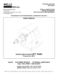
Installation Guide
Network Camera
WV-NW502S
WV-NW502SK
Model No.
Before attempting to connect or operate this product, please read these
instructions carefully and save this manual for future use.
The model number is abbreviated in some descriptions in this manual.
WARNING:
• To prevent fire or electric shock hazard, do not
expose this apparatus to rain or moisture.
• The apparatus should not be exposed to dripping or splashing and that no objects filled with
liquids, such as vases, should be placed on the
apparatus.
• All work related to the installation of this product should be made by qualified service personnel or system installers.
• The connections should comply with local electrical code.
For Canada
This Class A digital apparatus complies with
Canadian ICES-003.
CAUTION
RISK OF ELECTRIC
SHOCK DO NOT OPEN
CAUTION: TO REDUCE THE RISK OF ELECTRIC SHOCK,
DO NOT REMOVE COVER (OR BACK).
NO USER-SERVICEABLE PARTS INSIDE.
REFER SERVICING TO QUALIFIED SERVICE PERSONNEL.
The lightning flash with arrowhead symbol, within an equilateral triangle, is intended to alert
the user to the presence of uninsulated "dangerous voltage"
within the product's enclosure
that may be of sufficient magnitude to constitute a risk of electric shock to persons.
The exclamation point within an
equilateral triangle is intended to
alert the user to the presence of
important operating and maintenance (servicing) instructions in
the literature accompanying the
appliance.
Power disconnection. Unit with or without ON-OFF
switches have power supplied to the unit whenever
the power cord is inserted into the power source;
however, the unit is operational only when the ONOFF switch is in the ON position. Unplug the power
cord to disconnect the main power for all units.
2
For U.S.A
NOTE: This equipment has been tested and
found to comply with the limits for a Class A digital device, pursuant to Part 15 of the FCC Rules.
These limits are designed to provide reasonable
protection against harmful interference when the
equipment is operated in a commercial environment. This equipment generates, uses, and can
radiate radio frequency energy and, if not
installed and used in accordance with the instruction manual, may cause harmful interference to
radio communications.
Operation of this equipment in a residential area
is likely to cause harmful interference in which
case the user will be required to correct the interference at his own expense.
FCC Caution: To assure continued compliance,
(example - use only shielded interface cables
when connecting to computer or peripheral
devices). Any changes or modifications not
expressly approved by the party responsible for
compliance could void the user’s authority to
operate this equipment.
For U.S.A
The serial number of this product may be found
on the surface of the unit.
You should note the model number and serial
number of this unit in the space provided and
retain this book as a permanent record of your
purchase to aid identification in the event of
theft.
Model No.
Serial No.
Contents
Important safety instructions ...................................................................................................... 4
Limitation of liability .................................................................................................................... 5
Disclaimer of warranty ................................................................................................................ 5
Preface ....................................................................................................................................... 6
Main functions ............................................................................................................................ 6
About the user manuals ............................................................................................................. 7
System requirements for a PC ................................................................................................... 7
Trademarks and registered trademarks ..................................................................................... 8
About copyright and licence ....................................................................................................... 8
Network security ......................................................................................................................... 9
Precautions ................................................................................................................................ 10
Precautions for Installation ......................................................................................................... 13
Major operating controls and their functions .............................................................................. 15
Preparations ............................................................................................................................... 17
Camera installation .................................................................................................................... 21
Connection ................................................................................................................................. 29
Configure the network settings ................................................................................................... 35
Troubleshooting ......................................................................................................................... 37
Specifications ............................................................................................................................. 38
Standard accessories ................................................................................................................. 42
Optional accessories .................................................................................................................. 42
3
Important safety instructions
1) Read these instructions.
2) Keep these instructions.
3) Heed all warnings.
4) Follow all instructions.
5) Clean only with dry cloth.
6) Do not block any ventilation openings. Install in accordance with the manufacturer's
instructions.
7) Do not install near any heat sources such as radiators, heat registers, stoves, or other
apparatus (including amplifiers) that produce heat.
8) Do not defeat the safety purpose of the polarized or grounding-type plug. A polarized plug
has two blades with one wider than the other. A grounding type plug has two blades and a
third grounding prong. The wide blade or the third prong are provided for your safety. If the
provided plug does not fit into your outlet, consult an electrician for replacement of the
obsolete outlet.
9) Protect the power cord from being walked on or pinched particularly at plugs, convenience
receptacles, and the point where they exit from the apparatus.
10) Only use attachments/accessories specified by the manufacturer.
11) Use only with the cart, stand, tripod, bracket, or table specified by the manufacturer, or
sold with the apparatus. When a cart is used, use caution when moving the cart/apparatus
combination to avoid injury from tip-over.
S3125A
12) Unplug this apparatus during lightning storms or when unused for long periods of time.
4
Limitation of liability
THIS PUBLICATION IS PROVIDED "AS IS" WITHOUT WARRANTY OF ANY KIND, EITHER
EXPRESS OR IMPLIED, INCLUDING BUT NOT LIMITED TO, THE IMPLIED WARRANTIES OF
MERCHANTABILITY, FITNESS FOR ANY PARTICULAR PURPOSE, OR NON-INFRINGEMENT
OF THE THIRD PARTY'S RIGHT.
THIS PUBLICATION COULD INCLUDE TECHNICAL INACCURACIES OR TYPOGRAPHICAL
ERRORS. CHANGES ARE ADDED TO THE INFORMATION HEREIN, AT ANY TIME, FOR THE
IMPROVEMENTS OF THIS PUBLICATION AND/OR THE CORRESPONDING PRODUCT (S).
Disclaimer of warranty
IN NO EVENT SHALL Panasonic Corporation BE LIABLE TO ANY PARTY OR ANY PERSON,
EXCEPT FOR REPLACEMENT OR REASONABLE MAINTENANCE OF THE PRODUCT, FOR
THE CASES, INCLUDING BUT NOT LIMITED TO BELOW:
(1) ANY DAMAGE AND LOSS, INCLUDING WITHOUT LIMITATION, DIRECT OR INDIRECT,
SPECIAL, CONSEQUENTIAL OR EXEMPLARY, ARISING OUT OF OR RELATING TO THE
PRODUCT;
(2) PERSONAL INJURY OR ANY DAMAGE CAUSED BY INAPPROPRIATE USE OR NEGLIGENT OPERATION OF THE USER;
(3) UNAUTHORIZED DISASSEMBLE, REPAIR OR MODIFICATION OF THE PRODUCT BY THE
USER;
(4) INCONVENIENCE OR ANY LOSS ARISING WHEN IMAGES ARE NOT DISPLAYED, DUE
TO ANY REASON OR CAUSE INCLUDING ANY FAILURE OR PROBLEM OF THE PRODUCT;
(5) ANY PROBLEM, CONSEQUENTIAL INCONVENIENCE, OR LOSS OR DAMAGE, ARISING
OUT OF THE SYSTEM COMBINED BY THE DEVICES OF THIRD PARTY;
(6) ANY CLAIM OR ACTION FOR DAMAGES, BROUGHT BY ANY PERSON OR ORGANIZATION BEING A PHOTOGENIC SUBJECT, DUE TO VIOLATION OF PRIVACY WITH THE
RESULT OF THAT SURVEILLANCE-CAMERA'S PICTURE, INCLUDING SAVED DATA, FOR
SOME REASON, BECOMES PUBLIC OR IS USED FOR THE PURPOSE OTHER THAN SURVEILLANCE;
(7) LOSS OF REGISTERED DATA CAUSED BY ANY FAILURE.
5
Preface
Panasonic WV-NW502 Series cameras (WV-NW502S/WV-NW502SK) are designed to operate
using a PC on a network (10BASE-T/100BASE-TX), and can be installed under eaves (sheltered
outdoor).
By connecting to a network (LAN) or the Internet, images and audio from the camera can be
monitored on a PC via a network.
* The lens is optional for the case of WV-NW502SK.
Note:
• It is necessary to configure the network settings of the PC and its network environment to
monitor images from the camera on the PC. It is also necessary to install a web browser on
the PC.
Main functions
High resolution (2 048 x 1 536) image
Images with high resolution up to 2 048 x 1 536 (3 megapixel) can be transmitted.
MEGA Super Dynamic
Super-Dynamic compensates brightness on a pixel-to-pixel basis resulting in production of natural images even if a subject has various illumination intensities.
H.264/MPEG-4 and JPEG triple encoding
H.264/MPEG-4 dual stream output and JPEG output can be simultaneously provided.
* Either H.264 or MPEG-4 is selectable.
Auto back focus (ABF) function
ABF (Auto Back Focus) ensures easy installation and stable focus in both color and B/W
modes.
Black & white function
Images will be displayed clear even at night since the camera will be automatically switched
from the color mode to the black and white mode under low illumination condition.
* The operating sound might be heard during the mode change, however it does not indicate
any malfunction.
Power over Ethernet function
When connecting with a PoE (Power over Ethernet) device, power will be supplied by simply
connecting a LAN cable. (IEEE802.3af compliant)
Interactive communication with audio
By using the audio output connector and the microphone in connector, receiving audio from
the camera on a PC and transmitting audio from the PC to the camera is available.
6
SDHC/SD memory card function
Images can be recorded on an optional SDHC/SD memory card*1 both automatically (when
images fail to transmit using the FTP periodic transmission function) and manually.
The image on the SDHC/SD memory card can be playback on a web browser or downloaded
via network.
*1 Recommended SDHC/SD memory card (☞ page 41)
About the user manuals
There are 2 sets of this manual and the Operating Instructions (PDF).
The "Installation Guide" contains descriptions of how to install and connect this camera, and
how perform the required network settings.
Refer to the Operating Instructions (PDF) on the provided CD-ROM for descriptions of how to
perform the camera settings and how to operate this camera. Adobe® Reader® is required to
read PDF.
System requirements for a PC
CPU:
Memory:
Network Interface:
Audio Interface:
Monitor:
OS:
Web Browser:
Other:
Intel® CoreTM2 Duo 2.4 GHz or faster recommended
512 MB or more (A minimum of 1 GB memory is required when using
Microsoft® Windows® 7 or Microsoft® Windows Vista®.)
10BASE-T/100BASE-TX 1 port
Sound card (when using the audio function)
Image capture size: 1 024 x 768 pixels or more
Color: 24-bit True color or better
Microsoft® Windows® 7 Professional (64-bit)
Microsoft® Windows® 7 Professional (32-bit)
Microsoft® Windows Vista® Business SP1 (32-bit)
Microsoft® Windows® XP Professional SP3
Windows® Internet Explorer® 8.0
(Microsoft® Windows® 7 Professional (32-bit/64-bit))
Windows® Internet Explorer® 7.0
(Microsoft® Windows Vista® Business SP1 (32-bit))
Microsoft® Internet Explorer® 6.0 SP3
(Microsoft® Windows® XP Professional SP3)
CD-ROM Drive: It is necessary to read the operating instructions and use
the software on the provided CD-ROM.
DirectX® 9.0c or later
Adobe® Reader®: It is necessary to read the operating instructions on
the provided CD-ROM.
7
Important:
• When using a PC that does not meet the above requirements, displaying of images may
become slower or the web browser may become inoperable.
• Audio may not be heard if a sound card is not installed on a PC. Audio may be interrupted
depending on the network environment.
• Microsoft® Windows® XP Professional 64-bit Edition is not supported.
• When using IPv6 for communication, use Microsoft® Windows® 7 or Microsoft® Windows
Vista®.
Note:
• Refer to "Notes on Windows Vista® / Windows® 7" (PDF) for further information about system requirements for a PC and precautions when using Microsoft® Windows® 7 or
Microsoft® Windows Vista®.
Trademarks and registered trademarks
• Microsoft, Windows, Windows Vista, Internet Explorer, ActiveX and DirectX are either registered trademarks or trademarks of Microsoft Corporation in the United States and other
countries.
• Intel, Pentium and Intel Core are trademarks or registered trademarks of Intel Corporation
in the U.S. and other countries.
• Adobe and Reader are either registered trademarks or trademarks of Adobe Systems
Incorporated in the United States and/or other countries.
• SDHC logo is a trademark.
• Other names of companies and products contained in these operating instructions may be
trademarks or registered trademarks of their respective owners.
About copyright and licence
Distributing, copying, disassembling, reverse compiling, reverse engineering, and also exporting in violation of export laws of the software provided with this unit are expressly prohibited.
8
Network security
As you will use this unit connected to a network, your attention is called to the following security
risks.
q Leakage or theft of information through this unit
w Use of this unit for illegal operations by persons with malicious intent
e Interference with or stoppage of this unit by persons with malicious intent
It is your responsibility to take precautions such as those described below to protect yourself
against the above network security risks.
• Use this unit in a network secured by a firewall, etc.
• If this unit is connected to a network that includes PCs, make sure that the system is not
infected by computer viruses or other malicious entities (using a regularly updated antivirus program, anti-spyware program, etc.).
• Protect your network against unauthorized access by restricting users to those who log in
with an authorized user name and password.
• Apply measures such as user authentication to protect your network against leakage or
theft of information, including image data, authentication information (user names and
passwords), alarm mail information, FTP server information and DDNS server information.
• Do not install the camera in locations where the camera or the cables can be destroyed or
damaged by persons with malicious intent.
9
Precautions
Refer installation work to the dealer.
Installation work requires technique and
experiences. Failure to observe this may
cause fire, electric shock, injury, or damage
to the product.
Be sure to contact the dealer for installation,
relocation and power supply work.
Stop the operation immediately when
something is wrong with this product.
When smoke goes up from this product or
the smell of smoke comes from this product,
stop the operation immediately and contact
your dealer.
Turn the power off immediately and contact
qualified service personnel for service.
Do not attempt to disassemble or modify
this product.
Failure to observe this may cause fire or electric shock.
Consult the dealer for the repair or inspections.
Do not insert any foreign objects.
This could permanently damage this product.
Turn the power off immediately and contact
qualified service personnel for service.
Select an installation area that can support the total weight.
Selecting an inappropriate installation surface may cause the product to fall down or
topple over, resulting in injury.
Installation work shall be started after sufficient reinforcement.
Periodic inspections shall be conducted.
Rust on the metal parts or screws may cause
a fall of the product resulting in injury or accidents.
Consult the dealer for the inspections.
Do not use this product in an inflammable
atmosphere.
Failure to observe this may cause an explosion resulting in injury.
10
Avoid installing this bracket in the locations where salt damage occurs or corrosive gas is produced.
Otherwise, the mounting portions will deteriorate and accidents such as a fall of this product may occur.
Install this product at a vibration-free
place.
Failure to observe this may cause accidents
including falling.
Failure to observe this may cause screws
and bolts to be loosened resulting in injury
due to their falling.
The installation place shall be high
enough not to interfere with people or
object moving.
Failure to observe this may cause accidents
including falling.
Do not strike or give a strong shock to this
product.
Failure to observe this may cause injury or
fire.
Turn off the power before wiring.
Failure to observe this may cause electric
shock. In addition, a short circuit or wrong
wiring may cause fire.
The exclusively designed mount bracket
shall be used.
Failure to observe this may cause a drop
resulting in injury or accidents.
Use the exclusively designed mount bracket
for installation.
The screws and bolts shall be tightened to
the specified torque.
Failure to observe this may cause a drop
resulting in injury or accidents.
Do not rub the edges of metal parts with
your hand.
Failure to observe this may cause injury.
Turn the power off when cleaning of this
product.
Failure to observe this may cause injury.
[Precautions for use]
This product has no power switch.
When turning off the power, turn off a circuit
breaker.
To keep on using with stable performance
Do not use this product in hot and humid
conditions for a long time. Failure to observe
this causes component degradation resulting
in life shortening of this product.
(Recommended operating temperature:
+35 °C {95 °F} or lower)
Do not expose this camera to direct heat
sources such as a heater.
Do not touch the dome cover with your
bare hands.
A dirty dome cover causes deterioration of
picture quality.
Handle this product with care.
Do not abuse this product. Avoid striking,
shaking, etc. Failure to observe this may
cause trouble. If a strong shock or vibration
is applied to the enclosure, it may cause
damage or allow water to enter this product.
About the PC monitor
Displaying the same image on a CRT type
monitor for a long time may damage the
monitor. It is recommended to use a screensaver.
When an error is detected, this product
will restart automatically.
When an error is detected, this product will
restart automatically. This product will be
inoperable for around 2 minutes after the
restart just as when the power is turned on.
Product disposal/transfer
Data saved on the media used with this product may be categorized as "Personal
Information".
Therefore, if this product is handled by the
third party because of disposal, transfer or
repair, extreme care should be required for
data handling.
Cleaning this product body
Be sure to turn off the power before cleaning.
Failure to observe this may cause injury. Do
not use strong abrasive detergent when
cleaning this product. Otherwise, it may
cause discoloration.
When using a chemical cloth for cleaning,
read the caution provided with the chemical
cloth product.
When the dirt is hard to remove, use a
mild detergent and wipe gently.
When the dirt is hard to remove, use a mild
detergent and wipe gently. Then, wipe off the
remaining detergent with a dry cloth.
Cleaning the lens
Use a lens cleaning paper (used to clean
camera lenses or lenses of spectacles).
When using solvent, use an alcohols solvent
and do not use a thinner or a glass cleaner.
Transmission interval
Image transmission interval may become
slow depending on the network environment,
PC performance, shooting subject, access
number, etc.
About SDHC/SD memory card
• Before inserting the SDHC/SD memory
card, turn off the power of this product
first. Otherwise, it may cause malfunction
or damage data recorded on the
SDHC/SD memory card. Refer to page
25 for descriptions of how to insert/
remove an SDHC/SD memory card.
• When using an unformatted SDHC/SD
memory card, format it using this product. Recorded data on the SDHC/SD
memory card will be deleted when formatted. If an unformatted SDHC/SD
memory card or an SDHC/SD memory
card formatted with other devices is
used, the camera may not work properly
or performance deterioration may be
caused. Refer to the Operating
Instructions (PDF) for how to format an
SDHC/SD memory card.
11
• If another SDHC/SD memory card is
used, the camera may not work properly
or performance deterioration may be
caused.
Code label
The code labels (accessory) are required at
inquiry for trouble. Use caution not to lose
these labels. It is recommended to paste one
of the labels onto the CD-ROM case.
Discoloration on the CCD color filter
When continuously shooting a bright light
source such as a spotlight, the color filter of
the CCD may have deteriorated and it may
cause discoloration. Even when changing the
fixed shooting direction after continuously
shooting a spotlight for a certain period, the
discoloration may remain.
Do not aim the camera at strong light
sources.
A light source such as a spot light causes a
blooming (light bleeding) or a smear (vertical
lines).
Blight subject
Blooming
Indication label
Refer to the indication label on the bottom of
this product for the equipment classification
and power source, etc.
Consumable parts
The following are consumables: Replace
them in accordance with their lives. Their
lives vary depending on use environment
and conditions.
• Cooling fan
Lifetime: approx. 40 000 hours
Smear
MPEG-4 Visual Patent Portfolio License
This product is licensed under the MPEG-4
Visual Patent Portfolio License for the
personal and non-commercial use of a
consumer for (i) encoding video in
compliance with the MPEG-4 Visual Standard
("MPEG-4 Video") and/or (ii) decoding MPEG4 Video that was encoded by a consumer
engaged in a personal and non-commercial
activity and/or was obtained from a video
provider licensed by MPEG LA to provide
MPEG-4 Video. No license is granted or shall
be implied for any other use. Additional
information including that relating to
promotional, internal and commercial uses
and licensing may be obtained from MPEG
LA, LLC.
See http://www.mpegla.com.
12
AVC Patent Portfolio License
THIS PRODUCT IS LICENSED UNDER THE
AVC PATENT PORTFOLIO LICENSE FOR
THE PERSONAL USE OF A CONSUMER OR
OTHER USES IN WHICH IT DOES NOT
RECEIVE REMUNERATION TO (i) ENCODE
VIDEO IN COMPLIANCE WITH THE AVC
STANDARD ("AVC VIDEO") AND/OR (ii)
DECODE AVC VIDEO THAT WAS ENCODED
BY A CONSUMER ENGAGED IN A
PERSONAL ACTIVITY AND/OR WAS
OBTAINED FROM A VIDEO PROVIDER
LICENSED TO PROVIDE AVC VIDEO. NO
LICENSE IS GRANTED OR SHALL BE
IMPLIED FOR ANY OTHER USE.
ADDITIONAL INFORMATION MAY BE
OBTAINED FROM MPEG LA, L.L.C.
SEE HTTP://WWW.MPEGLA.COM
About the dehumidifying device
• This product has dehumidifying device to
keep the inside at low moisture level,
preventing condensation and quickly dissipating dew if produced.
• Dew may be produced depending on the
conditions of temperature, humidity,
winds, and rain, and it may take time to
dehumidify.
• Never seal the surfaces of the dehumidifying device.
Dehumidifying device
Precautions for Installation
Before start the installation/connection,
prepare the required devices and cables.
Before starting the connection, turn the
power of the devices including this product
and the PC off.
Warning: Refer installation work to the
dealer. Failure to observe this may
cause fire, electric shock, injury, or
damage to the product.
The product is designed to be installed
under eaves.
Do not install this product in locations subject
to direct sunlight.
Installing place
Contact your dealer for assistance if you are
unsure of an appropriate place in your particular environment.
• Make sure that the installation area is
strong enough to hold this product, such
as a concrete ceiling.
• Install the camera in the foundation area
of the architecture or where sufficient
strength is assured.
• If a ceiling board such as plaster board
is too weak to support the total weight,
the area shall be sufficiently reinforced.
Avoid installing in the following locations.
• Locations where a chemical agent is
used such as a swimming pool
• Locations subject to steam and oil smoke
such as a kitchen, Locations near flammable gas or vapor
• Locations where radiation or x-ray emissions are produced, Locations subject to
strong magnetic field or radio waves
• Locations where corrosive gas is produced, Locations where it may be damaged by briny air such as seashores
• Locations where the temperature is not
within –30 °C - +50 °C {–22 °F - 122 °F}.
• Locations subject to vibrations (This
product is not designed for on-vehicle
use.)
• If a ceiling board is too weak to support
the total weight, the area shall be sufficiently reinforced.
Do not install this product in a humid or
dust-laden environment.
Otherwise, lifetime of the internal parts may
be shortened.
Be sure to remove this product if it is not
in use.
Design and engineer the power supply
system to turn on/off the power of the
camera since this product does not have
the power switch.
About the network connection
When connecting to a network using the network cable of this product, observe the following.
• When wiring for the network, design and
engineer to not to be affected by thunder.
• It is impossible to install this product in
combination with a pan/tilt head.
Screw tightening
• The screws and bolts must be tightened
with an appropriate tightening torque
according to the material and strength of
the installation area.
• Do not use an impact driver. Use of an
impact driver may damage the screws or
cause tightening excessively.
• When a screw is tightened, make the
screw at a right angle to the surface.
• After tightening the screws or bolts, perform visual check to ensure tightening is
enough and there is no backlash.
13
Procure fixing screws separately.
The screws that secure this product are not
supplied. Prepare them according to the
material and strength of the area where the
product is to be installed.
Not remove or loosen screws
If the screws (7 pieces) on the rear of the
camera are loosened, camera trouble due to
water leakage or camera falling may occur.
Radio disturbance
When the camera is used near TV/radio
antenna, strong electric field or magnetic
field (near a motor, a transformer or a power
line), images may be distorted and noise
sound may be produced.
PoE (Power over Ethernet)
Use a PoE hub/device that is compliant with
IEEE802.3af standard.
Router
When connecting the camera to the Internet,
use a broadband router with the port forwarding function (NAT, IP masquerade).
Refer to the Operating Instructions (PDF) for
further information about the port forwarding
function.
Time & date setting
It is necessary to set the time and date
before putting this product into operation.
Refer to the Operating Instructions (PDF) on
the provided CD-ROM for further information
about the setting.
14
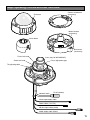
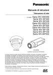
Major operating controls and their functions
Camera attachment
(accessory)
Enclosure
FRO
NT
P
TO
Mount bracket
(accessory)
Inner dome
SH
PU
Base cover
(accessory)
Focus lock knob
*Lens (only for WV-NW502S)
Focus adjustment grip
Zoom lock knob
Tilt adjusting table
Network cable
RJ-45 (female)
Alarm input/output cable
Power cable (12 V DC)
Mic/line input cable (white)
Audio output cable (black)
15
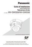
Panning lock screw
L
Tilting lock screw
K
OC
TOP
Panning table
SDHC/SD
memory card slot
MONITOR
OUT
INITIAL
SET
LINK
ABF
ACT
SD CARD/
ABF
Camera fixing screw
Monitor out connector
for adjustment
MONITOR
OUT
INITIAL SET
button
INITIAL
SET
LINK
Link LED
(Lights when the connection
is being established)
ACT
Auto-back-focus
button
ABF
SD CARD/
ABF
SDHC/SD memory card error LED/ABF LED
(Blinks when ABF is being performed)
Access LED
(Blinks when accessing a network)
• About the [INITIAL SET] button
Turn on the power of the camera while holding down this button, and wait for around 5 seconds
without releasing this button. Wait around 2 minutes after releasing the button. The camera will
start up and the settings including the network settings will be initialized. Before initializing the
settings, it is recommended to copy down the settings in advance.
16
Preparations
When installing the camera on a wall or a ceiling, there are two methods as specified below. (☞
pages 18 - 20)
• Using a two-gang junction box
• Using supplied mount bracket
Important:
• Procure 4 screws (M4) to secure the camera attachment (accessory) or the camera mount
bracket (accessory) to a wall or a ceiling according to the material of the installation area.
Do not use wood screws and nails.
Use anchor bolts (M4) for securing if the ceiling is made of concrete.
(Recommended tightening torque: 1.6 N·m {1.18 lbf·ft})
• Be sure to mount the camera attachment with the arrow facing upward.
• Required pull-out capacity of a single screw/bolt is 196 N {44.06 lbf} or more.
• If a ceiling board such as plaster board is too weak to support the total weight, the area
shall be sufficiently reinforced.
• When using an optional mounting bracket, refer to the operating instructions of the bracket
in use.
Installation Applicable mount
bracket
place
Recommended Number of
screw
screw
Minimum pull-out
strength (per 1 pc.)
Ceiling/wall (two-gang junction box)
M4
4 pcs.
196 N {44.06 lbf}
4 pcs.
196 N {44.06 lbf}
Mount bracket
Ceiling/wall*1 (approx. 350 g {0.77 lbs}) M4
WV-Q169
Ceiling
(approx. 700 g {1.55 lbs})
–
–
*2
*1 The conditions for securing the camera mount bracket to a wall or a ceiling are described
here.
*2 Make sure that the installed mount bracket can support more than 5 times of the weight of
the camera.
17
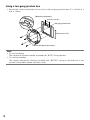
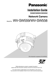
Using a two-gang junction box
• Secure the camera attachment (accessory) to the two-gang junction box (4" x 4") built in a
wall or ceiling.
[Mounting hole pattern]
46 mm {1-13/16"}
Two-gang junction box
FRO
NT
TOP
FRON
T
TOP
83.5 mm {3-9/16"}
Camera attachment (accessory)
Note:
• For wall mounting:
The camera attachment shall be mounted with "MTOP" facing upward.
• For ceiling mounting:
The camera attachment shall be mounted with “<FRONT” facing in the direction of the
camera front (model number indication face).
18
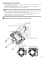
Using supplied mount bracket
• If the mount bracket (accessory) is used to mount the camera, mount the bracket on the
wall or ceiling first (see the blow).
Mount the camera attachment (accessory) with the supplied screws next (☞ page 20).
(Recommended tightening torque: 0.78 N·m {0.58 lbf·ft})
Note:
• When the camea is mounted on the wall or ceiling with a hole for cable running, or the camera is mounted using open wiring, the mount bracket is used.
• The female thread for conduit is compliant with ANSI NPSM (parallel pipe threads) 3/4".
The female thread for conduit can be removed using a hexagon wrench.
• Refer to page 33 for how to connect the conduit.
z Mount the mount bracket (accessory) on the wall or ceiling.
ø27 mm {1-1/16"}
Cable access hole
(A For use of the hole)
51 mm
{2"}
Mount bracket
A
B
A
Center of camera mount bracket
B
B
A
Female thread for conduit
(For use of the hole A)
85 mm {3-11/32"}
(For use of the hole B)
138 mm {5-7/16"}
85 mm
{3-11/32"}
138 mm
{5-7/16"}
19
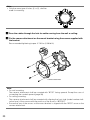
Note:
• Only the same type of holes, A or B, shall be
used for mounting.
B
A
A
B
B
A
A
B
x Pass the cables through the hole for cable running from the wall or ceiling.
c Fix the camera attachment on the mount bracket using the screws supplied with
the bracket.
Recommended tightening torque: 0.78 N·m {0.58 lbf·ft}
FRO
NT
TOP
Camera attachment
Note:
• For wall mounting:
The camera attachment shall be mounted with "MTOP" facing upward. Except the case of
connecting the conduit upward (page 33)
• For ceiling mounting:
The camera attachment shall be mounted with aligning the front side (model number indication face) of the camera with the position of the arrow in “<FRONT”.
• Ensure that any of the arrows on the mount bracket is aligned with the "MTOP" arrow on the
camera attachment.
20
Camera installation
z Mount the camera.
LOCK
OPEN
<Using a junction box>
q Connect each cable. (☞ page 29)
Waterproof the connecting portion. (☞ page 32.)
w Align the "OPEN" on the camera with the protrusion of the camera attachment.
e Engage the camera attachment fixing screws on the rear of the camera in the camera
mounting holes of the camera attachment and rotate the camera in the arrow direction to
secure the camera attachment and camera.
Ensure that the protrusion of the camera attachment is set to the "LOCK" position.
Projections
Camera mounting hole
FRO
NT
TOP
Camera attachment fixing screw
<Using the camera mount bracket>
q Attach the camera onto the camera
attachment while aligning the "OPEN"
mark of the camera with the projection of
the camera attachment.
21
OP
EN
CK
LO
LO
CK
OP
EN
Projection
Important:
• When mounting the camera body, cables
shall be run between the camera attachment and camera mount bracket as indicated by the arrow in the illustration.
* Cable running as indicated by the arrow
is an example. Cable running shall be
varied with installation environment.
OP
EN
LO
CK
OP
EN
Protrusion
LO
CK
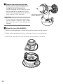
w Engage the rear-side screw of the camera with the screw hole of the camera
attachment and rotate the camera in the
direction of the arrow to secure the camera to the camera attachment.
Confirm that the embossed part of the
camera attachment is set in the "LOCK"
position.
e Connect the cables at the side of the
mount bracket. (☞ page 29)
Waterproof the connecting portion.
(☞ page 32)
Note:
• Disconnect the 12 V power source and
PoE power source to prevent power from
being supplied during mounting work.
22
Make cable
connections.
r Accommodate the connected cables
inside the cable guide of the camera
mount bracket.
Important:
• To prevent the cables from being caught
when the cover is attached, keep the
cables inside the cable guide.
Cable guide
Connected cable
Cable guide
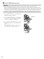
t Attach the base cover.
Base cover
y Use the bit for tamperproof screw
(accessory) to tighten the fixing screws
provided on both sides of the base
cover.
(Recommended tightening torque:
0.78 N·m {0.58 lbf·ft})
Base cover fixing screw
23
x Remove the enclosure and inner
dome from the main body by loosening the three fixing screws.
LOC
K
PU
SH
Loosen the three fixing screws by using
the provided bit for tamperproof screw.
Detach the inner dome while pushing the
parts with the "PUSH" indication.
Press the parts with the
"PUSH" indication.
PU
SH
Important:
• Do not hold the inner dome when carrying the camera. Otherwise, the camera
part may fall and it may damage the
camera.
c Mount the lens (WV-NW502SK)
q Before mounting the lens, remove the protection sheet from the camera.
w Refer to the operating instructions of the lens for how to mount the lens.
e Mount the optional lens to the camera by turning the lens clockwise.
W
24
T
r Insert the connector of lens into the connector of camera.
W
T
v Secure the camera to the bracket
with the camera fixing screw (red,
1position).
TOP
C
LO K
The illustration is an example of using
the accessory camera mount bracket.
ONI
TOR
OUT
INIT
Important:
• Be sure to tighten the camera fixing
screw.
Failure to observe this may cause camera trouble due to water leakage or camera falling.
(Recommended tightening torque:
0.78 N·m {0.58 lbf·ft})
IAL
SET
* The camera fixing
screw shall be
securely tightened.
Camera fixing screw (red)
LOC
K
b Remove the screw for transport protection (blue, 1 position) with a
Phillips screw driver.
Screw for transport
protection (blue)
25
n Insert an SDHC/SD memory card.
Important:
• Before inserting an SDHC/SD memory card, turn off the power of the camera first.
Insert an SDHC/SD memory card with the label face visible (see the illustration below).
Before removing the SDHC/SD memory card, select "Not use" for "SD memory card" on the
[SD memory card] tab of "Basic" on the setup menu first. Turn off the power after "Not use"
selection, and then unload the SDHC/SD memory card. (☞ Operating Instructions (PDF))
q Insert an SDHC/SD memory card into the
SDHC/SD memory card slot.
Label face
K
w Insert an SDHC/SD memory card into the
slot until it clicks into the place. When it
clicks, it is inserted into the place.
LOC
K
e To remove the SDHC/SD memory card,
push down the top of the card until it
clicks.
The SDHC/SD memory card will be
released and come up from the slot.
LOC
26
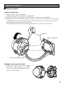
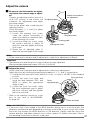
Adjust the camera
z Be sure to view the monitor for adjust-
75 °
K
ment when the camera angle is adjusted.
Monitor out connector
Connect an adjusting monitor (such as a
for adjustment
Tilt
adjusting
table
small LCD monitor) to the monitor out
connector (for adjustment) and adjust
the camera angle.
Turn on the power after connecting the
adjusting monitor.
Follow the steps q, w and e to adjust
the camera angle.
q Loosen the panning lock screw,
Tilting lock screw
rotate the camera horizontally to
adjust pan direction, and then tighten the panning lock screw.
Panning table
w Loosen the tilting lock screw, rotate
the camera vertically to adjust tilt
Panning lock screw
direction, and then tighten the tilting
lock screw.
e Rotate the tilt adjusting table to
adjust the azimuth angle of the image.
K
LOC
LOC
Note:
• At the same time for the pan and tilt adjustments, make focus adjustments of Step 2.
Important:
• The panning lock and tilting lock screws shall be securely tightened.
(Recommended tightening torque: 0.59 N·m {0.44 lbf·ft})
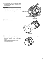
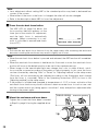
x Adjusts the focus.
At the same time for the pan and tilt adjustments, make focus adjustments.
Adjust the focus by following the adjusting procedure of q, w and e shown below.
q Hold down the auto back focus button for 5 sec. or more to set ABF to the standard
position.
Focus lock knob
w Loosen the zoom lock lever and
move the lever between TELE and
Focus
adjustment grip
WIDE to obtain the appropriate
angle of view.
e Loosen the focus lock knob, rotate
the focus adjustment grip to adjust
the focus coarsely, and then tighten
the focus lock knob.
* Refer to the operting instructions of the
lens for the case of WV-NW502SK.
(☞ page 24)
ABF
OR
NIT OUT
MO
AL
INITI SET
Zoom lock knob
Note:<WV-NW502SK>
• If the zoom ring is fully rotated in the WIDE direction during use of a vari-focal lens, the
periphery may become dark depending on the lens to be used. In such a case, fully rotate
the focus ring in either the NEAR direction or FAR direction, slightly rotate the ring in the
reverse direction, and adjust the back focus of the camera. For further information, refer to
the operating instructions for the lens to be used.
27
Note:
• Lens adjustment without setting ABF to the standard position may lead to darkened four
corners of the screen.
• When either of the zoom or the focus is changed, the other will also be changed.
• Refer to the description about ABF for focus fine adjustment.
c Press the auto back focus button.
The ABF LED (☞ page 16) blinks, the
focus position indicator appears on the
lower part of the monitor for adjustment,
and the back focus is automatically
adjusted. (When connecting to a network, it is possible to execute and check
from a PC.)
NEAR
FAR
.........|..........
INDICATOR XXXX FOCUSING
Important:
• Activate the auto back focus function from the setup menu after mounting the enclosure
because mounting the enclosure may result in slightly out of focus.
Note:
• When the auto back focus button is pressed and released, the ABF function will immediately start.
• When the auto back focus button is held down for 5 seconds or more, the auto back focus
position will move to the default position to be set for lens replacement, etc.
• When images in the near-infrared light area change from color to white & black, out-offocus may be occurred according to the nature of optical property. In this case, the focus
can be corrected by selecting "Auto" or "Preset" for "Adjusting method" on the setup menu
(The focus will not automatically be adjusted according to the illumination level change
once the focus is corrected.) Refer to the Operating Instructions (PDF) for how to set
[Adjusting method] on the setup menu.
• If the product is installed and operated at temperatures of –10°C or lower, activation of the
auto back focus function may result in failure to obtain accurate focus. In such a case, wait
until the camera warms up (taking approx. more than 1 hour) and perform adjustment after
turning on the power again.
v Mount the enclosure and inner dome.
Cutout
Cutout for
for mounting
mounting
Groove for mounting
Tighten the screws that have been loosened
in Step 2 in page 24 using the supplied driver
bit.
LOC
K
LOC
K
PU
SH
28
Important:
• Securely tighten all the fixing screws (x3) of enclosure.
Otherwise, water exposure may cause damage or malfunction of camera, or camera dropping may result in injury.
(Recommended tightening torque: 0.78 N·m {0.58 lbf·ft})
• Attach the inner dome in accordance with the lens direction to not to change the lens direction.
• Check if the tabs of the inner dome are firmly fit.
• Remove the cushioning (pink sheet) from the inside of the dome and the protection sheet
from the outside of the dome.
Connection
Turn off a circuit breaker before making a connection. Before start the connection, prepare the
required devices and cables.
Network cable
RJ-45 (female)
Alarm input/output cable 4P alarm cable (accessory)
2P power cable (accessory)
Power cable
(12 V DC)
Mic/line input cable (white)
Audio output cable (black)
12 V DC (red)
GND (black)
Power cable
12 V DC
Red
Positive
Black
Negative
z Connect the microphone to MIC/LINE IN (for use of the audio reception function).
Input impedance:
2 kΩ ±10 %
Recommended cable length: 1 m {3.3'} or less (for microphone input)
10 m {33'} or less (for microphone input)
Recommended microphone: Plug-in power type microphone (option)
Connect a mini plug (ø3.5 mm).
• Supply voltage:
2.5 V ±0.5 V
• Recommended sensitivity of microphone: –48 dB±3 dB (0 dB=1 V/Pa,1 kHz}
Important:
• Connect/disconnect the external speaker cables or audio/video cables after turning off the
power of the camera and the amplifier. Otherwise, loud noise may come out from the
speaker.
29
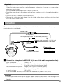
x Connect an external amplifier-embedded speaker to the audio output connector
(for use of the audio transmission function).
Connect a stereo mini plug (ø3.5 mm) (monaural output).
• Recommended cable length: 10 m {33 ft} or less
c Connect the alarm input/output cable.
Rating of ALARM IN/OUT
<Ratings>
• ALARM OUT
AUX OUT / EXPOSURE OUT
Output specification: Open collector output (maximum applied voltage: DC 20 V)
Open: DC 4 - 5 V by internal pull-up
Close: Output voltage 1 V DC or less (50 mA or less)
• ALARM IN1 / DAY NIGHT IN
ALARM IN2
ALARM IN3
Input specification:
Non-voltage make contact input
(DC 4 - 5 V internal pull-up)
OFF: Open or DC 4 - 5 V
ON: Make contact with GND (required drive current: 1 mA or more)
Note:
• Check if rating of an external device such as a sensor is applicable to the rating of this
product by referring to the provided operating instructions.
4P alarm cable (accessory) pin configuration
1
Black
GND
2
Gray
ALARM IN3/AUX OUT/EXPOSURE OUT
(Alarm input terminal 3/AUX output terminal/exposure timing output terminal)
3
Red
ALARM IN2/ALARM OUT
(Alarm input terminal 2/alarm output terminal)
4
Green
ALARM IN1/DAY NIGHT IN
(Alarm input terminal 1/color-BW selection input terminal)
30
v Connect a LAN cable (category 5 or better) to the network cable.
b Connect the power cable.
Important:
• The power supply of 12 V DC shall be insulated against 120 V AC.
• When using 12 V DC power supply
Connect the output cable of the AC adapter (option) to the 2P power cable.
• When using PoE (IEEE802.3af compliant)
Connect an Ethernet cable (category 5 or better) between a PoE device (such as a hub) and
the network connector cable of the camera.
Important:
• Use all 4 pairs (8 pins) of the LAN cable.
• The maximum cable length is 100 m {328'}.
• Make sure that the PoE device in use is compliant with IEEE802.3af standard.
• When connecting both the 12 V DC power supply and the PoE device for power supply,
PoE will be used for power supply.
• When disconnecting the LAN cable once, reconnect the cable after about 2 seconds.
When the cable is quickly connected, the power may not be supplied from the PoE device.
31
Waterproof treatment for the cable joint sections
Adequate waterproof treatment is required for the cables when installing the camera with
cables exposed or installing it under the eaves. The camera body is waterproof, but the cable
ends are not waterproof.
Be sure to use the supplied butyl rubber tape at the points where the cables are connected to
apply waterproof treatment in the following procedure. Failure to observe this or use of a tape
other than the provided butyl rubber tape (such as a vinyl tape) may cause water leakage
resulting in malfunction.
When using a LAN cable
Wind the tape in a half-overlapping manner
When using the ALARM IN/OUT cable, POWER cable, MIC/LINE IN cable and AUDIO OUT
cable
Wind the tape in a half-overlapping manner
Important:
• Waterproof treatment is also to be applied to the 2P power cable (provided), the 4P alarm
cable (provided) and other connection cables if they are subject to rain.
Note:
• How to wind the supplied waterproof butyl tape
Stretch the tape by approx. twice (see the illustration at right) and wind it around the cable.
Stretch the tape to about twice.
Insufficient tape stretch causes insufficient waterproofing.
• To install this product outdoors, be sure to water2x
proof the cables. Waterproof grade (IEC IP66 or
equivalent) is applied to this product only when it is installed correctly as described in
these operating instructions and appropriate waterproof treatment is applied. The mount
brackets are not waterproofed.
32
Important:
• If open wiring is conducted, be sure to use conduits and run the cables inside the tubes to
protect the cables from direct sunlight.
• When connecting the conduit at the lateral or bottom position, any of the arrow marks on
the bracket shall be at the top.
• When connecting the conduit upward, mount the camera attachment with the arrow position on either left or right side.
<When connecting the conduit sideward or downward>
Arrow mark
Connecting
conduit
<When connecting the conduit upward>
FRONT
TOP
• For installation on the wall, do not connect the conduit at the upper side to prevent water
from being stored in the bracket. If water remains inside, the dehumidifying device cannot
function properly.
• Installation work shall be such that there is no intrusion of water into the architecture
through the conduits having been joined.
33
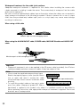
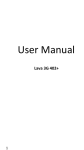
Connection example when connecting to a network using a
PoE hub
Speaker with amplifier
(option)
Video monitor
(for adjustment use only)
PoE device (hub)
LAN cable
(category 5 or better,
straight)
Microphone (option)
LAN cable
(category 5 or better,
straight)
PC
Speaker with amplifier
(option)
LAN cable
(category 5 or better, straight)
Microphone (option)
Video monitor
(for adjustment use only)
<Required cable>
LAN cable (category 5 or better, straight)
Important:
• The video monitor is used for checking the adjustment of the angular field of view when
installing the camera or when servicing. It is not provided for recording/monitoring use.
• Use a switching hub or a router which is compliant with 10BASE-T/100BASE-TX.
• When the image capture mode is changed, the images displayed on the video monitor may
sometimes be distorted until the camera is restarted.
• Power supply is required for each network camera. When using a PoE device (hub), 12 V
DC power supply is unnecessary.
34
Configure the network settings
Install the software
Before installing the software, read the readme file on the provided CD-ROM first.
Software included on the provided CD-ROM
• Panasonic IP setting software
Configure the network settings of the camera. Refer to the following for further information.
• Viewer Software "Network Camera View4"
It is necessary to install the viewer software "Network Camera Viewer4" to display images
on a PC. Install the viewer software by double-clicking the "nwcv4setup.exe" icon on the
provided CD-ROM.
Configure the network settings of the camera using the
Panasonic IP setting software
It is possible to configure the network settings of the camera using the IP setup software on the
provided CD-ROM.
When using multiple cameras, it is necessary to configure the network settings of each camera
independently.
If the Panasonic IP setting software does not work, configure the network settings of the camera
and the PC individually on the "Network setup" page of the setup menu. Refer to the Operating
Instructions (PDF) for further information.
Important:
• When using Microsoft® Windows Vista®, the "Windows Security Alert" window may be displayed when starting the IP setup software. In this case, disable "User Account Control"
from the control panel.
• For the security enhancement, the MAC address/IP address of the camera to be configured will not be displayed when around 20 minutes have passed after turning on the power
of the camera. (when the effective period is set to "20 minutes" in the IP setup)
• Panasonic IP setting software is inoperable in other subnets via the same router.
• This camera cannot be displayed or set with an older version of the IP setup software (version 2.xx).
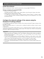
35
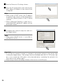
z Start the Panasonic IP setting software.
x Click the [IP setting] button after selecting the
MAC address/IP address of the camera to be
configured.
Note:
• When using a DHCP server, the IP address
assigned to the camera can be displayed by
clicking the [Refresh] button of the IP setting
software.
• When a duplicate IP address is used, the corresponding MAC address/IP address will be
displayed shaded.
c Complete each network setup item and click
the [Apply] button.
Note:
• When using a DHCP server, it is possible to
set "DNS" to "AUTO".
Important:
• It may take for around 2 minutes to complete to upload the settings to the camera after
clicking the [Apply] button. The settings may be invalidated when the 12 V DC power supply is cut or when the LAN cable is disconnected before completing the upload.In this
case, perform the settings again.
• When using a firewall (including software), allow access to all UDP ports.
36
Troubleshooting
Before asking for repairs, check the symptoms with the following table.
Contact your dealer if a problem cannot be solved even after checking and trying the solution
in the table or a problem is not described below.
Symptom
Power is not turned on.
Power indicator not lit.
Cause/solution
When using DC power supply
• Is DC 12 V power supply connect to
the 2P power supply cable?
→ Check whether the connection is
appropriately established.
When using a PoE device for power
supply
• Are the PoE device and the network
connector cable of the camera connected using a LAN cable ?
→ Check whether the connection is
appropriately established.
• Depending on the PoE device, the
power supply will stop when the
demanded power exceeds its total
power limit for all PoE ports.
→ Refer to the operating instructions
of the PoE device in use.
• Is "Off" set for "Link/Access LED" on
the "Basic" page?
→ Set "On" for "Link/Access LED".
Reference
pages
31
Operating
Instructions
(PDF)
37
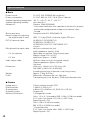
Specifications
● Basic
Power source:
Power consumption:
Ambient operating temperature:
Ambient operating humidity:
Waterproof:
Shock resistance:
Monitor output (for adjusting
the angular field of view):
EXT I/O terminal cable:
Microphone/Line input cable:
For microphone:
For line:
Audio output cable:
Dimensions:
Weight:
Finish:
12 V DC, PoE (IEEE802.3af compliant)
12 V DC: 630 mA, PoE: 7.6 W (Class 0 device)
–30 °C - +50 °C {–22 °F - 122 °F} *1
Less than 90 %
Camera: IP66 (IEC60529)
* Only when installation work specified in this book is properly
performed and appropriate waterproof treatment is performed
Compliant with 50 J IEC60068-2-75
VBS: 1.0 V [p-p]/75 Ω, composite signal, RCA jack
ALARM IN1 / DAY/NIGHT IN
ALARM IN2 / ALARM OUT
ALARM IN3 / AUX OUT / EXPOSURE OUT
x1 each
ø3.5 mm monaural mini jack
Input impedance: Approx. 2 kΩ
Applicable microphone: Plug-in power type
Supply voltage: 2.5 V ±0.5 V
Input level: Approx. –10 dBV
ø3.5 mm stereo mini jack (monaural output)
Output impedance: Approx. 600 Ω
Line level
ø164 mm x 146 mm (H) x 191.5 mm (W)
{ø6-15/32" x 5-3/4" (H) x 5-9/16"(W)}
(including protrusion of the base cover fixing screw)
Approx. 1.8 kg {3.97 lbs}
Main body: Aluminum die cast, light gray
Transparent part (over the lens): Clear polycarbonate resin
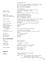
● Camera
Image sensor:
Effective pixels:
Scanning area:
Scanning system:
Minimum illumination:
38
1/3 inch interline transfer CCD
1 296 (H) x 976 (V) x 2
4.86 mm (H) x 3.65 mm (V) {3/16" (H) x 1/8" (V)}
Progressive
1.3 megapixels mode
Color: 1.0 lx {0.1 footcandle}, BW: 0.08 lx {0.008 footcandle}
(F1.2, Auto slow shutter: Off (1/30 s), AGC: High,
Super-Dynamic: Off)
Color: 0.06 lx {0.006 footcandle},
BW: 0.005 lx {0.0005 footcandle}
* Converted value
(F1.2, Auto slow shutter: Max. 16/30 s, AGC: High,
Super-Dynamic: Off)
Super-Dynamic:
Dynamic range:
Gain (AGC):
Adaptive black stretch:
Light control mode setting:
Shutter speed:
Auto slow shutter:
Black & white mode:
White balance:
Digital noise reduction:
Image stabilizer:
Video analytics
Face detection:
Privacy zone:
Camera title on screen:
VMD alarm:
Auto back focus:
ALC lens drive:
Lens mount:
3 megapixels mode
Color: 2.0 lx {0.2 footcandle}, BW: 0.16 lx {0.016 footcandle}
(F1.2, Auto slow shutter: Off (1/30 s), AGC: High)
Color: 0.12 lx {0.012 footcandle},
BW: 0.01 lx {0.001 footcandle}
* Converted value
(F1.2, Auto slow shutter: Max. 16/30 s, AGC: High)
On/Off (only at 1.3 megapixels mode)
52 dB typ.
(Super-Dynamic: On, Light control: Indoor scene)
On(Low)/On(Mid)/On(High)/Off
On/Off (only at Super-Dynamic Off)
Indoor scene/Outdoor scene/ELC
(ELC: only at Super-Dynamic Off)
Off(1/30), 3/100, 2/100, 1/100, 1/250, 1/500, 1/1 000, 1/2 000,
1/4 000, 1/10 000 (only at Super-Dynamic Off)
Off, Max. 2/30s, Max. 4/30s, Max. 6/30s, Max. 10/30s,
Max. 16/30s
On/Off/Auto 1(Normal)/Auto 2(IR Light)/Auto 3(SCC)
ATW1/ATW2/AWC
High/Low
On/Off
On/Off (with the XML notification setting)
On/Off (up to 8 zones available)
Up to 16 characters (alphanumeric characters, marks)
On/Off
On/Off, 4 areas available
AUTO/PRESET/FIX
DC drive
CS-mount
● Lens (WV-NW502S)
Type:
Focal length:
F number:
Focus range:
Angle of view:
Adjusting angle:
2.8x vari-focal lens
2.8 mm - 8.0 mm
1:1.2 (WIDE) - 1:1.8 (TELE)
∞ - 0.3 m
Horizontal: 35.0 ° (TELE) - 100.0 ° (WIDE)
Vertical: 26.2 ° (TELE) - 73.4 ° (WIDE)
Panning range: ±170 °
Tilting range: ±75 °
Azimuth range: ±100 °
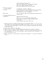
● Network
Network:
Resolution:
10BASE-T/100BASE-TX, RJ45 connector
1.3 megapixels mode
H.264
[4:3]: 1 280 x 960/SVGA (800 x 600)/VGA (640 x
480)/QVGA (320 x 240), max. 30 fps
[16:9]: 1 280 x 720/640 x 360/320 x 180, max. 30 fps
39
MPEG-4 [4:3]: VGA (640 x 480)/QVGA (320 x 240),
max. 30 fps
JPEG
[4:3]: 1 280 x 960/SVGA (800 x 600)/VGA (640 x
480)/QVGA(320 x 240), max. 30 fps
[16:9]: 1 280 x 720/640 x 360/320 x 180, max. 30 fps
3 megapixel mode
H.264
[4:3]: 1 280 x 960/VGA (640 x 480)/QVGA (320 x
240), max. 15 fps
[16:9]: 1 920 x 1 080/640 x 360/320 x 240,
max. 15 fps
MPEG-4 [4:3]: VGA (640 x 480)/QVGA (320 x 240),
max. 15 fps
JPEG
[4:3]: 2 048 x 1 536/1 280 x 960/VGA (640 x 480),
max. 15 fps
[16:9]: 1 920 x 1 080/640 x 360/320 x 180,
max. 15 fps
Image compression
method*2 *3:
Transmission interval:
Audio compression method:
Bandwidth control:
Protocol:
OS*4 *5:
Browser:
40
H.264/MPEG4:
Image quality: Low/Normal/FineTransmission
type: Unicast/Multicast
Video bit rate:
Constant bit rate:
64kbps/128kbps/256kbps/384kbps/512kbps/
768kbps/1024kbps/1536kbps/2048kbps/
3072kbps/4096kbps/*8192kbps/Unlimited
* only in H.264 mode
Frame rate priority:
1fps/3fps/5fps/7.5fps/10fps/15fps/*20fps/
*30fps
* only in 1.3 megapixel mode
JPEG:
Image quality: 0 SUPER FINE/1 FINE/2/3/4/5
NORMAL/6/7/8/9 LOW (10 steps: 0-9)
Transmission type: PULL/PUSH
0.1 fps - 30 fps (JPEG frame rate will be restricted when
displaying both JPEG and H.264/MPEG-4 images.)
G.726 (ADPCM) 32kbps/16kbps
Unlimited/64kbps/128kbps/256kbps/384kbps/512kbps/
768kbps/1024kbps/2048kbps/4096kbps/8192kbps
IPv6: TCP/IP, UDP/IP, HTTP, RTP, FTP, SMTP, DNS, NTP,
SNMP
IPv4: TCP/IP, UDP/IP, HTTP, RTSP, RTP, RTP/RTCP, FTP,
SMTP, DHCP, DNS, DDNS, NTP, SNMP
Microsoft® Windows® 7 Professional (64-bit)
Microsoft® Windows® 7 Professional (32-bit)
Microsoft® Windows Vista® Business SP1 (32-bit)
Microsoft® Windows® XP Professional SP3
Windows® Internet Explorer® 8.0
(Microsoft® Windows® 7 Professional (32-bit/64-bit))
Windows® Internet Explorer® 7.0
(Microsoft® Windows Vista® Business SP1 (32-bit))
Microsoft® Internet Explorer® 6.0 SP3
(Microsoft® Windows® XP Professional SP3)
Maximum concurrent
access number:
FTP client:
Multi-screen:
Compatible SDHC/SD memory
card (option):
14 (Depends on network conditions)
Alarm image transmission, FTP periodic transmission (When
the FTP transmission is failed, backup on an optional
SDHC/SD memory card is available.)
Up to 16 camera images can be displayed simultaneously on
a multi-screen.
Manufactured by Panasonic
SDHC memory card: 4 GB, 8 GB, 16 GB, 32 GB
SD memory card: 64 MB, 128 MB, 256 MB, 512 MB,
1 GB, 2 GB
(except miniSD card and microSD card)
*1 When the camera is installed and operated in low temperatures below –10 °C {14 °F}, normal images may not be obtained immediately after startup. In such a case, wait until the
camera warms up (taking approx. more than 1 hour) and perform adjustment after turning
on the power again.
*2 Either H.264 or MPEG-4 is selectable.
*3 Transmission for 2 streams can be individually set in the same compression method.
*4 Refer to "Notes on Windows Vista® / Windows® 7" (PDF) for further information about system requirements for a PC and precautions when using Microsoft® Windows® 7 or
Microsoft® Windows Vista®.
*5 When using IPv6 for communication, use Microsoft® Windows® 7 or Microsoft® Windows
Vista®.
41
Standard accessories
Installation Guide (this book)...................................... 1 volume
Warranty card............................................................. 1 set
CD-ROM*1 .................................................................. 1 pc.
Code label*2 ............................................................... 1 pc.
The following parts are used during installation procedures.
4P alarm cable ........................................................... 1 pc.
Camera attachment.................................................... 1 pc.
2P power cable ......................................................... 1 pc.
Fixing screws (M4 x 8 mm) ........................................ 5 pcs.
(1 piece of spare screw included)
Base cover ................................................................. 1 pc.
Mount bracket ............................................................ 1 pc.
Bit for tamperproof screw........................................... 1 pc.
Butyl tape ................................................................... 1 pc.
*1 The CD-ROM contains the operating instructions (PDFs) and different kinds of tool software
programs.
*2 This label may be required for network management. The network administrator shall retain
the code label.
Optional accessories
Ceiling mount bracket ................................... WV-Q169
Smoke dome cover ....................................... WV-CW4S
42
43
Panasonic System Communications
Company of North America,
Unit of Panasonic Corporation of North America
www.panasonic.com/business/
For customer support, call 1.800.528.6747
Three Panasonic Way, Secaucus, New Jersey 07094 U.S.A.
Panasonic Canada Inc.
5770 Ambler Drive, Mississauga, Ontario, L4W 2T3 Canada
(905)624-5010
www.panasonic.ca
© Panasonic System Networks Co., Ltd. 2012
Ns0609-5012
3TR005933FZA
Printed in China